1
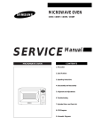
MICROWAVE OVEN
CE124CF
SERVICE
Manual
CONTENTS
MICROWAVE OVEN
1. Precaution
2. Specifications
3. Operating Instructions
HEISSLUFT
MIKROWELLE
GRILL
LEISTUNG
MW+HEISSL
AUFTAUEN
MW+GRILL
4. Disassembly and Reassembly
SCHNELLGERICHTE
1.GETRÄNKE
2.FOLIENKARTOFFEL
3.PIZZA
4.POMMES FRITES
GRILL+HEISSL
5.HAMBURGER/FISCHSTÄBCHEN
6.REIS/NUDELN
GARAUTOMATIK
7.POPCORN
AUFWARMEN
8.FERTIGGERICHTE
9.QUICHE/AUFLAUF
PLUS
10.EINTOPF
11.SUPPE/SAUCE
UHR
12.REIS/NUDELN
GAR.AUTOMATIK
5. Alignment and Adjustments
13.RIND
14.SCHWEIN
15.GEFLÜGEL
16.GEFLÜGELSTÜCKE
MINUS
17.FISCH
18.GEMÜSE(FRISCH)
19.GEMÜSE (GEFROREN)
ZEIT/GEWICHT
LÖSCHEN
START
CE124CF
6. Troubleshooting
7. Exploded Views and Parts List
8. PCB Diagrams
9. Schematic Diagrams
1. Precaution
Follow these special safety precautions. Although the microwave oven is completely safe during ordinary
use, repair work can be extremely hazardous due to possible exposure to microwave radiation, as well as
potentially lethal high voltages and currents.
1-1 Safety precautions (
)
1. All repairs should be done in accordance
with the procedures described in this
manual. This product complies with
Federal Performance Standard 21 CFR
Subchapter J (DHHS).
2. Microwave emission check should be
performed to prior to servicing if the oven is
operative.
3. If the oven operates with the door open :
Instruct the user not to operate the oven and
contact the manufacturer and the center for
devices and radiological health immediatly.
4. Notify the Central Service Center if the
microwave leakage exceeds 5 mW/cm2
5. Check all grounds.
6. Do not power the MWO from a "2-prong"
AC cord. Be sure that all of the built-in
protective devices are replaced. Restore any
missing protective shields.
7. When reinstalling the chassis and its
assemblies, be sure to restore all protective
devices, including: nonmetallic control
knobs and compartment covers.
8. Make sure that there are no cabinet openings
through which people--particularly
children--might insert objects and contact
dangerous voltages. Examples: Lamp hole,
ventilation slots.
9. Inform the manufacturer of any oven found
to have emmission in excess of 5 mW/cm2,
Make repairs to bring the unit into
compliance at no cost to owner and try to
determine cause.
Instruct owner not to use oven until it has
been brought into compliance.
CENTRAL SERVICE CENTER
10. Service technicians should remove their
watches while repairing an MWO.
Samsung Electronics
11. To avoid any possible radiation hazard,
replace parts in accordance with the wiring
diagram. Also, use only the exact
replacements for the following parts:
Primary and secondary interlock switches,
interlock monitor switch.
12. If the fuse is blown by the Interlock Monitor
Switch: Replace all of the following at the
same time: Primary, door sensing switch
and power relay, as well as the Interlock
Monitor Switch. The correct adjustment of
these switches is described elsewhere in this
manual. Make sure that the fuse has the
correct rating for the particular model being
repaired.
13. Design Alteration Warning:
Use exact replacement parts only, i.e.,
only those that are specified in the
drawings and parts lists of this manual.
This is especially important for the
Interlock switches, described above.
Never alter or add to the mechanical or
electrical design of the MWO. Any design
changes or additions will void the
manufacturer's warranty.10.Always unplug
the unit's AC power cord from the AC
power source before attempting to
remove or reinstall any component or
assembly.
14. Never defeat any of the B+ voltage
interlocks. Do not apply AC power to the
unit (or any of its assemblies) unless all
solid-state heat sinks are correctly installed.
15. Some semiconductor ("solid state") devices
are easily damaged by static electricity. Such
components are called Electrostatically
Sensitive Devices (ESDs). Examples include
integrated circuits and field-effect
transistors.
Immediately before handling any
semiconductor components or assemblies,
drain the electrostatic charge from your
body by touching a known earth ground.
16. Always connect a test instrument's ground
lead to the instrument chassis ground before
connecting the positive lead; always remove
the instrument's ground lead last.
1-1
Pretaution
1-2 Special Servicing Precautions (Continued)
17. When checking the continuity of the
switches or transformer, always make sure
that the power is OFF, and one of the lead
wires is disconnected.
18. Components that are critical for safety are
indicated in the circuit diagram by
shading,
or
.
19. Use replacement components that have the
same ratings, especially for flame resistance
and dielectric strength specifications. A
replacement part that does not have the
same safety characteristics as the original
might create shock, fire or other hazards.
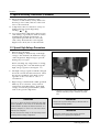
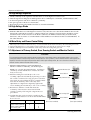
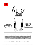
1-3 Special High Voltage Precautions
1. High Voltage Warning
Do not attempt to measureany of the high
voltages--this includes the filament voltage
of the magnetron. High voltage is present
during any cook cycle.
Before touching any components or wiring,
always unplug the oven and discharge the
high voltage capacitor (See Figure 1-1)
2. The high-voltage capacitor remains charged
about 30 seconds after disconnection. Short
the negative terminal of the high-voltage
capacitor to the oven chassis. (Use a
screwdriver.)
3. High voltage is maintained within specified
limits by close-tolerance, safety-related
components and adjustments. If the high
voltage exceeds the specified limits, check
each of the special components.
=> : Touch chassis side first then short to the high voltage
capacitor terminal by using a screwdriver or jumper
wire.
PRECAUTION
PRECAUTION
There exists HIGH VOLTAGE ELECTRICITY with high
current capabilities in the circuits of the HIGH VOLTAGE
TRANSFORMER secondary and filament terminals. It is
extremely dangerous to work on or near these circuits
with the oven energized.
DO NOT measure the voltage in the high voltage circuit
including filament voltage of magnetron.
Never touch any circuit wiring with your hand nor with an
insulated tool during operation.
1-2
PRECAUTION
Servicemen should remove their watches whenever
working close to or replacing the magnetron.
Samsung Electronics
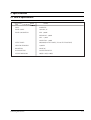
2. Specifications
2-1 Table of Specifications
ITEM
MODEL
CE124CF
TIMER
99 MINUTES
POWER SOURCE
230V 50Hz, AC
POWER CONSUMPTION
MAX : 3,000W
MICROWAVE : 1,600W
GRILL : 1,300W
CONVECTION : 1,400W
OUTPUT POWER
90W/900W(10 LEVEL POWER) (IEC-705 TEST PROCEDURE)
OPERATING FREQUENCY
2,450MHz
MAGNETRON
OM75P(10)
COOLING METHOD
COOLING FAN MOTOR
OUTSIDE DIMENSIONS
558(W) x 381(H) x 496(D)
Samsung Electronics
2-1
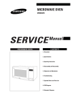
3. Operating Instructions
3-1 Control Panel
MICROWAVE
CONVECTION
WINDOW DISPLAY AND INDICATOR LIGHTS
GRILL
P/LEVEL
MW+CONV.
MW+GRILL
* Funtion Indicator Lights indicate which cooking
funtion is being set or used.
* Digital Display shows time of day or time left to cook.
* Power Indicator Light Indicates which power is being
set or used.
DEFROST
INSTANT COOK
1.DRINKS
2.JACKET POTATO
3.PIZZA
4.OVEN CHIPS
5.BURGERS/FISH FINGERS
GRILL+CONV.
AUTO/DISH
6.RICE/PASTA
7.POPCORN
FUNCTION SELECTOR BUTTONS
AUTO REHEAT
8.PLATED MEAL
* Clock set
* Microwave, Power Level select
* Defrost, Auto cook and Dish select
* More, Less(Min Plus, Min Minus)
* Convection, grill, Combination cook
* Timer/Weight set
* Stop/Cancel, Start
9.PIE/QUICHE
MORE
10.CASSEROLE
11.SOUP/SAUCE
12.RICE/PASTA(REHEAT)
CLOCK
AUTO COOK
13.ROAST BEEF
14.ROAST PORK
15.ROAST CHICKEN
16.CHICKEN PIECE
LESS
17.FISH
18.FRESH VEGETABLE
19.FROZEN VEGETABLE
TIMER/WEIGHT
STOP/CANCEL
START
CE124CF
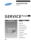
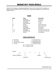
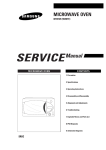
3-2 Features & Accessories
THERMIISTOR SENSOR
OVEN LAMP
HEATER GRILL
HEISSLUFT
MIKROWELLE
GRILL
LEISTUNG
MW+HEISSL
AUFTAUEN
WINDOW DISPLAY
SCHNELLGERICHTE
MW+GRILL
1.GETRÄNKE
2.FOLIENKARTOFFEL
3.PIZZA
4.POMMES FRITES
5.HAMBURGER/FISCHSTÄBCHEN
GRILL+HEISSL
6.REIS/NUDELN
GARAUTOMATIK
7.POPCORN
AUFWARMEN
8.FERTIGGERICHTE
9.QUICHE/AUFLAUF
OVEN DOOR
PLUS
10.EINTOPF
11.SUPPE/SAUCE
12.REIS/NUDELN
UHR
GAR.AUTOMATIK
13.RIND
14.SCHWEIN
CONTROL PANEL
15.GEFLÜGEL
16.GEFLÜGELSTÜCKE
MINUS
17.FISCH
18.GEMÜSE(FRISCH)
19.GEMÜSE (GEFROREN)
ZEIT/GEWICHT
LÖSCHEN
GLASS TRAY
START
CE124CF
OPEN DOOR
BARBECUE BAR
HOLDER
COUPLER
3-1
ROATING BASE
TURNTABLE
TRAY
ROLLER RING
METAL
RACKS
BARBECUE
BAR
HOLDER
CRUSTY PLATE
MULTY SPIT
Samsung Electronics
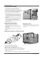
4. Disassembly and Reassembly
4-1 Replacement of Fan Motor and HVCapacitor
(Top View)
screw 1)
1. Remove out panel.
2. Disconnect all connectors and terminals.
3. Remove a screw 1) securing the fan motor
bracket.
4. Remove two screws 2) at back plate.
5. Remove a screw 3) securing HVC bracket for
removal of HVC.
(Rear View)
screw 2)
screw 3) of HVC bracket
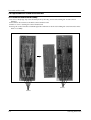
4-2 Replacement of Damper, Magnetron
1. After removing out panel and magnetron
supporter, disconnect all the terminals and
connectors from magnetron and damper assembly.
2. Remove four screws (1) securing damper Ass'y.
3. Remove two screws (2) securing magnetron
thermostat.
4. Remove four magnetron flange nuts at top.
=> : 1) When removing the magnetron, make sure that
its antenna does not hit any adjacent parts, or it
may be damaged.
2) when replacing the magnetron, be sure to
remount the magnetron gasket in the correct
position and make sure the gasket is in good
condition.
3) Never install magnetron without metalic gasket
plate, which should be packed with each
magnetron to prevent microwave leakage.
4) Check microwave leakage after repair work is
carried out on magnetron.
4-3 Replacement of Lamp
4 Magnetron flange nuts at top
Pin plate
screws (1) of damper
screws
(2) of
Magnetron
thermostat
Choke Coil
screws of lamp
1) Remove out panel.
2) Remove two screws securing lamp holder.
Thermistor Probe
Thermal Cutout Switch
Samsung Electronics
4-1
Disassembly and Reassembly
4-4 Replacement of Door Assembly
Remove hex bolts securing the upper hinge and
lower hinge. Then remove the door Ass'y.
Flange Bolts of upper hinge
• After replacement of the defective component parts
of the door, reassemble it and follow the instructions
below for proper installation and adjustment so as
to prevent an excessive microwave leakage.
1. When mounting the door to the oven, be sure to
adjust the door parallel to the bottom line of the
oven face plate by moving the upper hinge and
lower hinge in the direction necessary for proper
alignment.
2. Adjust so that the door has no play between the
inner door surface and oven front surface. If the
door assembly is not mounted properly,
microwave may leak from the clearance between
the door and oven.
3. Perform the microwave leakage test.
4-5 Replacement of H.V.Transformer
1. Discharge the high voltage capacitor.
2. Disconnect all the leads from the high voltage
transformer.
3. Remove the mounting bolts on the high voltage
transformer.
4. When replacing, connect the leads correctly and
firmly.
Bolts & a screw of lower hinge
4-6 Replacement of Fuse
Disconnect the oven from the power source and
remove the 15A fuse in the fuse holder in noise
filter Ass'y.
4-7 Replacement of Casing Ass'y and Convection Heater
12
10
11
6
9
4
2
5
8
7
3
screws 1) of convection heater
1. Remove out panel and back panel.
2. Disconnect all connectors and terminals.
3. Remove air duct and support-back.
4. Remove screws 1) securing convection heater Ass'y.
5. Remove nut'2', blade fan'3', spring washer'4' and bushing'5'.
6. Remove convection assembly '11', '12' and cooling fan'10'.
7. Remove four screws '6'.
8. Remove heater cover '7' '9'. Then heater adiabatic '8' will be disassembled.
4-2
Samsung Electronics
Disassembly and Reassembly
4-8 Replacement of Drive Motor
1. Take out the glass tray, guide roller and coupler from cavity.
2. Turn the oven upside down to replace the drive motor.
3. Cut out the drive motor cover with nipper and remove it from the base plate.
4. Disconnect all the lead wires from the drive motor.
5. Remove screws 1) securing the drive motor to the cavity.
6. Take out the drive motor.
7. When replacing the drive motor, be sure to remount it in the correct position.
After replacing the drive motor, insert
boss to this tab and fit with two
screws 2).
Cut eight points of drive motor cover.
screws 1)
Lead wires
screws 2)
4-9 Replacement of Control Circuit Board
• Be sure to ground any static electric charge in you
body and never touch the touch control circuitry.
1. Remove 3 screws securing control panel Ass'y to oven front.
2. Remove screws holding control panel bracket '7' to control panel '1'.
3. Disconnect film connector from PCBoard assembly '9'.
4. Remove 3 screws securing PCB Ass'y.
5. Pull out membrane'4', window display'5' and door button'2'.
6
9
3
CO
NV
EC
GR
INS
TA
1.D NT CO
RIN
2.JAC KS OK
3.P KET
IZZ PO
TATO
4.O A
VE
5.B NCH
UR
IPS
6.R GERS
ICE
7.P /PA /FISH
OP
ST
FIN
AU CORN A
GE
TO
RS
8.P REHE
LA
9.P TED AT
ME
IE/
10. QUICH AL
CA
11. SSER E
SO
12. UP/SAOLE
RIC
AU EPAS UCE
TO
13. COOKTA(RE
RO
HE
14. AST
AT)
RO
BE
15. AST EF
RO
PO
16. AST RK
CH
CH
17. ICKEN ICK
FIS
PIE EN
18. H
CE
FR
19. ESH
FROZ VE
EN GETA
VEGE BLE
TABL
E
TIO
N
MIC
RO
WA
VE
ILL
MW
+CON
V.
P/L
EVEL
MW
+G
RIL
L
DE
FROS
T
8
GR
ILL
+CON
V.
AU
TO
D/D
ISH
CLOC
K
MO
RE
/LE
SS
TIM
ER
/WEIG
HT
CA
NC
EL
7
STAR
T
2
Samsung Electronics
1
4-3
Disassembly and Reassembly
4-6 Replacement of Control Circuit Board
4-6-1 Removal of Control Box Assembly
1. Be sure to disclyarge any static electricity from your body, and avoid touching the "Touch control"
clrcuitry.
2. Disconnect the connectors from the control circuit board.
3. Remove screws securing the control circuit bord.
4. Lift up the control circuit board from right side and remove the hooks holding the contol circuit board to
the box assembly.
Screws
Screws
4-4
Samsung Electronics
5. Alignment and Adjustments
PRECAUTION
1. High voltage is present at the high voltage terminals during any cook cycle.
2. It is neither necessary nor advisable to attempt measurement of the high voltage.
3. Before touching any oven components or wiring, always unplug the oven from its power source and discharge the high voltage
capacitor.
5-1 High Voltage Transformer
1. Remove connectors from the transformer terminals
and check continuity.
2. Normal resistance readings are as follows:
Filament Terminals
Secondary Terminal
Secondary ..........................Approx. 66W
Filament .............................Approx. 0W
Primary...............................Approx. 1.250W
(Room temperature = 20˚C)
Primary
Terminals
5-2 Low Voltage Transformer
1. The low voltage transformer is located on the
control circuit board.
2. Remove the low voltage transformer from the
PCB Ass'y and check continuity.
3. Normal resistor reading is shown in the table.
L.V.T SPEC. : SLV-105E
Terminals
Resistance
1~2(Input)
3~4(Output)
5~6(Output)
290Ω
4.0Ω
1.0Ω
5-3 Magnetron
Continuity checks can indicate only an open
filament or a shorted magnetron. To diagnose an
open filament or shorted magnetron :
1. Isolate the magnetron from the circuit by
disconnecting its leads.
2. A continuity check across the magnetron filament
terminals should indicate one ohm or less.
3. A continuity check between each filament terminal
and magnetron case should read open.
Magnetron Antenna
Gasket Plate
Cooling Fins
Samsung Electronics
5-1
Alignment and Adjustments
5-4 High Voltage Capacitor
1. Check continuity of the capacitor with the meter set at the highest resistance scale.
2. Once the capacitor is charged, a normal capacitor shows continuity for a short time, and then indicates 9MΩ.
3. A shorted capacitor will show continuous continuity.
4. An open capacitor will show constant 9MΩ.
5. Resistance between each terminal and chassis should read infinite.
5-5 High Voltage Diode
1. Isolate the diode from the circuit by disconnecting its leads.
2. With the ohm-meter set at the highest resistance scale, measure across the diode terminals. Reverse the
meter leads and read the resistance. A meter with 6V, 9V or higher voltage batteries should be used to
check the front-to back resistance of the diode (otherwise an infinite resistance may be read in both
directions). The resistance of a normal diode will be infinite in one direction and several hundred KΩ in
the other direction.
5-6 Main Relay and Power Control Relay
1. The relays are located on the PCB Ass'y. Isolate them from the main circuit by disconnecting the leads.
2. Operate the microwave oven with a water load in the oven. Set the power level set to high.
3. Check continuity between terminals of the relays after the start pad is pressed.
5-7 Adjustment of Primary Switch, Door Sensing Switch and Monitor Switch
Precaution
For continued protection against radiation hazard, replace parts in accordance with the wiring diagram and be sure to use the
correct part number for the following switches: Primary and door sensing switches, and the interlock monitor switch (replace all
together). Then follow the adjustment procedures below. After repair and adjustment, be sure to check the continuity of all
interlock switches and the interlock monitor switch.
1. When mounting Primary switch and Interlock
Monitor switch to Latch Body, consult the figure.
NOTE : No specific adjustment during installation
of Primary switch and Monitor switch to the latch
body is necessary.
Interlock Monitor S/W
2. When mounting the Latch Body to the oven
assembly, adjust the Latch Body by moving it so that
the oven door will not have any play in it. Check for
play in the door by pulling the door assembly. Make
sure that the latch keys move smoothly after
adjustment is completed. Completely tighten the
screws holding the Latch Body to the oven assembly.
Lever Slider A
Primary Interlock S/W
3. Reconnect to Monitor switch and check the
continuity of the monitor circuit and all latch
switches again by following the components test
procedures.
Door Sensing S/W
4. Confirm that the gap between the switch housing
and the switch actuator is no more than 0.5mm when
door is closed.
Primary switch
Monitor switch (COM-NC)
Monitor switch (COM-NO)
Door Sensing S/W
5-2
Door Open
Door Closed
∞
0
∞
∞
0
∞
0
0
Lever Slider B
(Door Close Condition)
(Door Open Condition)
Samsung Electronics
Alignment and Adjustments
5-8 Output Power of Magnetron
CAUTION
MICROWAVE RADIATION
PERSONNEL SHOULD NOT ALLOW EXPOSURE TO MICROWAVE RADIATION FROM MICROWAVE GENERATOR OR OTHER PARTS
CONDUCTING MICROWAVE ENERGY.
The output power of the magnetron can be measured by performing a water temperature rise test.
Equipment needed :
* Two 1-liter cylindrical borosilicate glass vessel (Outside diameter 190 mm)
* One glass thermometer with mercury column
NOTE: Check line voltage under load. Low voltage will lower the magnetron output. Make all temperature
and time tests with accurate equipment.
1. Fill the one liter glass vessel with water.
2. Stir water in glass vessel with thermometer, and record glass vessel's temperature ("T1", 10±1˚C).
3. After moving the water into another glass vessel, place it in the center of the cooking tray. Set the oven to high
power and operate for 48seconds exactly. (1.5 seconds included as a holding time of magnetron oscillation:)
4. When heating is finished, stir the water again with the thermometer and measure the temperature ("T2").
5. Subtract T1 from T2. This will give you the water temperature rise. (∆T)
6. The output power is obtained by the following formula;
Output Power =
4.187 x 1000 x ∆T+0.88xMcx(T2-T0)
46.5
46.5: Heating Time (sec)
4.187 : Coefficient for Water
1000 : Water (cc)
∆T : Temperature Rise (T2-T1)
Mc : Cylindrical borosilicate glass weight
To : Room temperature.
7. Normal temperature rise for this model is 9˚C to 11˚C at 'HIGH'.
NOTE 1: Variations or errors in the test procedure will cause a variance in the temperature rise.
Additional power test should be made if temperature rise is marginal.
NOTE 2: Output power in watts is computed by multiplying the temperature rise (step 5) by a factor of 90
times the of centigrade temperature.
5-9 Microwave Heat Distribution - Heat Evenness
The microwave heat distribution can be checked indirectly by measuring the water temperature rise at
certain positions in the oven:
1. Prepare five beakers made of 'Pyrex', having 100 milliliters capacity each.
2. Measure exactly 100milliliters off water load with a measuring cylinder, and pour into each beaker.
3. Measure the temperature of each water load. (Readings shall be taken to the first place of decimals.)
4. Put each beaker in place on the cooking tray as illustrated in figure below. Start heating.
5. After heating for 2 minutes, measure the water temperature in each beaker.
6. Microwave heat distribution rate can be calculated as follows:
Heat Distribution =
Minimum
Temperature Rise
Maximum
Temperature Rise
D
X 100(%)
Beaker
D
The result should exceed 65%.
D/4
D/4
D/4
D/4
Samsung Electronics
Cooking Tray
5-3
Alignment and Adjustments
5-10 Procedure for Measurement of Microwave Energy Leakage
1) Pour 275±15cc of 20±5˚C(68±9˚F) water in a beaker
which is graduated to 600cc, and place the beaker in
the center of the oven.
2) Start to operate the oven and measure the leakage by
using a microwave energy survey meter.
3) Set survey meter with dual ranges to 2,450MHz.
4) When measuring the leakage, always use the 2 inch
spacer cone with the probe. Hold the probe
perpendicular to the cabinet door. Place the spacer
cone of the probe on the door and/or cabinet door
seam and move along the seam, the door viewing
window and the exhaust openings moving the probe
in a clockwise direction at a rate of 1 inch/sec. If the leakage testing of the cabinet door seam is taken near
a corner of the door, keep the probe perpendicular to the areas making sure that the probe end at the base
of the cone does not get closer than 5cm to any metal. If it gets closer than 5cm, erroneous readings may result.
5) Measured leakage must be less than 4mW/cm2, after repair or adjustment.
HEISSLUFT
MIKROWELLE
GRILL
LEISTUNG
MW+HEISSL
MW+GRILL
AUFTAUEN
SCHNELLGERICHTE
1.GETRÄNKE
2.FOLIENKARTOFFEL
3.PIZZA
4.POMMES FRITES
GRILL+HEISSL
5.HAMBURGER/FISCHSTÄBCHEN
6.REIS/NUDELN
GARAUTOMATIK
7.POPCORN
AUFWARMEN
8.FERTIGGERICHTE
9.QUICHE/AUFLAUF
PLUS
10.EINTOPF
11.SUPPE/SAUCE
UHR
12.REIS/NUDELN
GAR.AUTOMATIK
13.RIND
14.SCHWEIN
15.GEFLÜGEL
16.GEFLÜGELSTÜCKE
MINUS
17.FISCH
18.GEMÜSE(FRISCH)
19.GEMÜSE (GEFROREN)
ZEIT/GEWICHT
LÖSCHEN
START
CE124CF
Maximum allowable leakage is 5mW/cm2.
4mW/cm2 is used to allow for measurement and meter accuracy
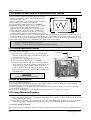
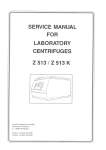
5-11 Check for Microwave Leakage
1. Remove the outer panel.
2. Pour 275±15cc of 20±5˚C(68±9˚F) water in a beaker
which is graduated to 600cc, and place the beaker in
the center of the oven.
3. Start the oven at the highest power level.
4. Set survey meter dual ranges to 2,450MHz.
5. Using the survey meter and spacer cone as described
above, measure arnear the opening of magnetron, the
surface of the air guide and the surface of the wave
guide as shown in the following photo.( but avoid the
high voltage components.) The neading should be less
than 4mW/cm2.
Survey Meter
Spacer Cone
WARNING
AVOID THE HIGH VOLTAGE COMPONENTS.
5-12 Note on Measurement
1) Do not exceed the limited scale.
2) The test probe must be held on the grip of the handle, otherwise a false reading may result when the
operator's hand is between the handle and the probe.
3) When high leakage is suspected, do not move the probe horizontally along the oven surface; this may
cause damage to the probe.
4) Follow the recommendation of the manufacturer of the microwave energy survey meter.
5-13 Leakage Measuring Procedure
5-13-1 Record keeping and notification after measurement
1) After adjustment and repair of a radiarion preventing device, make a repair record for the measured
values, and keep the data.
2) If the radiation leakage is more than 4 mW/cm2 after determining that all parts are in good condition,
functioning properly and the identical parts are replaced as listed in this manual notift that fact to ;
CENTRAL SERVICE CENTER
5-13-2 At least once a year have the microwave energy survey meter checked for accuracy by its manufacturer.
5-4
Samsung Electronics
6. Troubleshooting
PRECAUTION
1. CHECK GROUNDING BEFORE CHECKING FOR TROUBLE.
2. BE CAREFUL OF THE HIGH VOLTAGE CIRCUIT.
3. DISCHARGE THE HIGH VOLTAGE CAPACITOR.
4. WHEN CHECKING THE CONTINUITY OF THE SWITCHES OR TRANSFORMER, DISCONNECT ONE LEAD WIRE FROM THESE
PARTS AND THEN CHECK CONTINUITY WITHOUT THE POWER SOURCE ON. TO DO OTHERWISE MAY RESULT IN A FALSE
READING OR DAMAGE TO YOUR METER.
5. DO NOT TOUCH ANY PART OF THE CIRCUIT OR THE CONTROL CIRCUIT BOARD, SINCE STATIC DISCHARGE MAY DAMAGE IT.
ALWAYS TOUCH GROUND WHILE WORKING ON IT TO DISCHARGE ANY STATIC CHARGE BUILT UP.
6-1 Electrical Malfunction
SYMPTOM
CAUSE
CORRECTIONS
Oven is dead.
Fuse is OK.
No display and no operation at all.
1. Open or loose lead wire harness
2. Open thermal cutout (Magnetron)
3. Open low voltage transformer
4. Defective Ass'y PCB
Check fan motor when thermal cutout is defective.
No display and no operation at all.
Fuse is blown.
1. Shorted lead wire harness
2. Defective primary latch switch (NOTE 1)
3. Defective monitor switch (NOTE1)
4. Shorted HVCapacitor
5. Shorted HVTransformer (NOTE2)
Check adjustment of primary, interlock monitor,
power relay, door sensing switch.
Check Ass'y PCB when LVT is defective.
NOTE 1: All of these switches must be replaced at the same time.
(refer to adjustment instructions)
Check continuity of power relay contacts and if it has continuity, replace power
relay also.
NOTE 2: When HVTransformer is replaced, check diode and magnetron also.
Oven does not accept
key input (Program)
Timer starts countdown but no
microwave oscillation.
(No heat while oven lamp and
fan motor turn on.)
Samsung Electronics
1. Key input is not in-Sequence
2. Open or loose connection of membrane
key pad to Ass'y PCB
3. Shorted or open membrane panel
4. Defective Ass'y PCB
Refer to operation procedure.
1. Off-alignment of latch switches
2. Open or loose connection of high voltage
circuit especially magnetron filament
circuit
NOTE: Large contact resistance will bring
lower magnetron filament voltage and
cause magnetron to lower output and/or
intermittent oscillation.
3. Defective high voltage components
H.V.Transformer
H.V.Capacitor
H.V.Diode,H.V.Fuse
Magnetron
4. Open or loose wiring of power relay
5. Defective primary latch switch
6. Defective power relay or Ass'y PCB
Adjust door and latch switches.
Replace PCB main.
Check high voltage component according to
component test procedure and replace if it is
defective.
Replace PCB main.
6-1
Troubleshooting
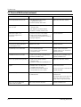
6-1 Electrical Malfunction(continued)
SYMPTOM
CAUSE
CORRECTIONS
Oven lamp and fan motor turn on
1. Misadjustment or loose wiring
of primary latch switch
2. Defective primary latch switch
Adjust door and latch switches.
Oven can program but timer
does not start.
1. Open or loose wiring of secondary
interlock switch
2. Off-alignment of primary interlock
3. Defective secondary interlock S/W
Adjust door and interlock switches.
Microwave output is low;.
Oven takes longer time to
cook food.
1. Decrease in power source voltage.
2. Open or loose wiring of magnetron
filament circuit. (Intermittent oscillation))
3. Aging of magnetron
Consult electrician.
Fan motor turns on when plugged in
Loose wiring of door sensing switch
Check wire of door sensing switch.
Oven does not operate and return
to the plugged in mode.
Defective Ass'y PCB
Replace PCB main.
Loud buzzing noise can be heard.
1. Loose fan and fan motor
2. Loose screws on H.V.Transformer
3. Shorted H.V.Diode
Tighten screws of fan motor.
Tighten screws of H.V.Transformer.
Replace H.V.Diode.
Turntable motor does not rotate.
1. Open or loose wiring of turntable motor.
2. Defective turntable motor.
Check the wire of turntable motor
Replace turntable motor.
Oven stops operation during cooking
1. Open or loose wiring of primary
interlock switch
2. Operation of thermal cutout(Magnetron)
Adjust door and latch switches.
Sparks
1. Metallic ware or cooking dishes
touching on the oven wall.
2. Ceramic ware trimmed with gold or
silver powder also causes sparks.
Inform the customer.
Do not use any type of cookware with
metallic trimming.
Uneven cooking
Uneven intensity of microwave due to
its characteristics.
Wrap thinner parts of the food with
aluminum foil.
Use plastic wrap or cover with a lid.
Stir once or twice while cooking
foods such as soup, cocoa, or milk.
Noise from the turntable motor
when it starts to operate.
Noise may result from the motor.
Replace turntable motor.
6-2
Samsung Electronics
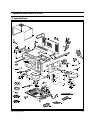
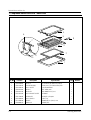
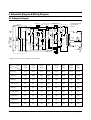
7. Exploded Views and Parts List
7-1 Exploded Views
1
74
3
7
10
4
64
2
65
6
66
70
67
5
12
72
73
42
77
18
13
71
69
68
78
14
21
63
20
16
15
86
19
83
55
30
34
51
33
17
29
53
32
37
82
35
31
39
45
52
54
76
22
41
36
88
49
75
28
44
25
85
50 43
47
24
23
84
26
27
87
57
56
40
38
48
46
61
8
9
59
79
58
62
60
80
81
Samsung Electronics
7-1
Exploded Views and Parts List
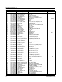
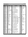
7-2 Main Parts List
Ref. No.
1
2
3
4
5
6
7
8
9
10
12
13
14
15
16
17
18
19
20
21
22
23
24
25
26
27
28
29
30
31
32
33
35
34
35
36
37
38
39
40
41
42
43
44
45
46
47
48
49
50
51
52
53
54
55
56
57
58
59
60
7-2
Parts No.
DE92-90315A
DE61-30100A
DE92-90053A
DE39-40453E
DE62-90016B
DE71-60316A
DE92-90179A
DE65-20022A
DE39-20075G
DE39-40229E
DE31-10020A
2501-000234
DE61-50266A
DE59-40001A
DE39-30102A
DE91-70061A
DE61-30099A
DE27-10020A
OM75PH(10)ESS
DE47-20101A
DE66-90028A
DE72-20014A
DE34-20026A
DE70-90016A
DE61-50231A
DE31-10052A
DE60-60026A
DE67-60037A
DE31-10057A
DE72-40034A
DE72-40037A
DE62-90015B
DE71-60216A
DE71-60230D
DE71-60216A
DE66-40027A
3405-000175
DE61-30127A
3405-000178
DE61-30129A
DE66-90062A
DE91-70100A
DE26-10033A
DE61-50232A
DE60-60026A
DE72-80023B
DE39-40117A
DE92-90247A
DE61-50236A
DE31-10039A
DE47-70016E
DE61-30140A
DE62-90014B
DE71-60229D
DE70-40073A
DE80-10049A
DE91-40091A
DE26-20084A
DE61-80065A
DE61-40029A
Description
ASSY-DAMPER COVER
SUPPORTER-BACK
ASSY-COVER AIR
WIRE HARNESS-B
ADIABATIC-L
COVER-ADIABATIC-L
ASSY-BACK PANEL
BUSHING CORD
ASSY POWER CORD
WIRE HARNESS-A
MOTOR-FAN
C-OIL
BRACKET-HVC
DIODE-H.V
WIRE LEAD-B
ASSY-H.V.FUSE
SUPPORTER-MGT
COIL-MC CHOKE
ASSY-MAGNETRON
THERMOSTAT
LEVER-DAMPER
CAM
SWITCH-MICRO
SHEET-INSK K
BRACKET-DAMPER
MOTOR-SYNCHRONOUS
PIN-DAMPER
COUPLER-BARBECUE
MOTOR-SYNCHRONOUS
DAMPER-SILICON
DAMPER-PLATE
ADIABATIC-R
COVER-DAMPER
COVER-ADIABATIC-R
COVER-DAMPER
BODY-LATCH
SWITCH-MICRO
SUPPORTER-PCB
SWITCH-MICRO
SUPPORTER-PCB
LEVER-DOOR
ASSY-RESISTOR
TRANS-H.V
BRACKET-DOOR LEVER
PIN-DAMPER
SHAFT-BARBECUE
WIRE HARNESS-C
ASSY-COUPLER
BRACKET-COVER MOTOR
MOTOR-SYNCHRONOUS
HEATER-GRILL
SUPPORTER-HEATER
ADIABATIC-L
COVER-ADIABATIC-L
PLATE-CEILING
BASE-PLATE
ASSY-NOISE FILTER
TRANS-L.V
HINGE-LOWER
FOOT
Specification
RE-1280
SECC,T0.6
RE-1200/1280/1270
230V,RE-1280(SAW),AMFO
EGF-E3019-PBS,T10,W180,L180,AL
SBHG1-M,T0.5
RE-1280
IC002
UD13A1,230V15A,L1500,BLK,CE102
230V,RE-1280(SAW),AMFO
AMM90-004ATEB
SCH-2121134B1,1.13F,2100VAC,54X35
SECC,T0.6
HVR-1X-32B-12
L540,2GA2
THV060T-0800-H,5KV/0/8A WH
SECC,T0.8
TC,101
OM75PH(10)ESSS
PW2N(160/60)
POM-KEP,44G
POM(KEP,F20-02),RE-909CG
VP331A-OD(PT2
POLYESTER,T0.5,W45,L24
SECC,T0.8
M2LB49ZR02,DAMPER-MOTOR
MSWR3
AL
MULJ24ZR03,SPIT-MOTOR
SILICONE
SECC,T0.6
EGF-E3019-PBS,T15,W346,L282,AL
NYLON#66-2411GF,143.7G
SBHG1-M,T0.5
NYLON#66-2411GF,143.7G
NULON#662411GF6,HB,NTR
250V,15A,200gf,SPST-NO
DANC-6N
250V,15A,200gf,SPST-NO
DASS-T9N
NYLON#66,2411GF6,HB,NTR
RE-1280(SAW),10W,30-J
Y247STC,230V,50HZ,AC2260/3.3V
SECC,T1.5
MSWR3
RE-909CG
RE-909CG
RE-1270/1280,EUROPE
SECC,T0.8,RE-909CG
MVLB51ZR11,220/240V50H
230V,1300W,39OHM,D7.0,RE-1280,
ALUMINA,10G,RE-650
EGF-E3019-PBS,T15,W351,L136,AL
SBHG1-M,T0.5
MICA-SHEET,T0.5
SBHG1-R,T1.0
RE-1200,250V,15A,1200
RE-1280STC,230V,50HZ,AC16/3V,R
SBC1,T3.0,DARCON
DASF-330,RE-909CG
Q'ty
1
1
1
1
1
1
1
1
1
1
1
1
1
1
1
1
1
1
1
1
1
1
1
1
1
1
1
1
1
1
1
1
1
1
1
1
1
1
2
4
1
1
1
1
1
1
1
1
1
1
1
1
1
1
1
1
1
1
1
4
Remarks
COVE/L
MGT
Samsung Electronics
Exploded Views and Parts List
7-2 Main Parts List
Ref. No.
Parts No.
Description
Specification
Q'ty
Remarks
61
DE92-90019B
ASSY-RACK WIRE
CE124CF,HIGH,MAGENTA
1
62
DE92-90019S
ASSY-WIRE RACK
CE124CF,LOW
1
63
DE61-90094A
HOLDER-BARBECUE
PTFE,9G
1
64
DE32-10013A
SENSOR-THERMISTOR
PT-312-K2
1
65
4713-000168
LAMP-INCANDESCENT
230V,-,25W,ORG
1
66
DE47-40021A
SOCKET-LAMP
E/14(22.225)
1
67
DE61-50234A
BRACKET-LAMP
SECC,T0.8
1
68
DE71-60267A
COVER-LAMP
STS304,T0.4
1
69
DE67-40066A
GLASS-PLATE
TEMP-GLASS,T3.2
1
70
DE61-50282E
BRACKET-HINGE U
SBHG1-A,T1.2
1
71
DE61-70060A
SPRING-PLATE
SK-5,T0.5
1
72
DE62-90028C
ADIABATIC-UPPER
T6,W399,L353.8,CERAMIC,WOOL
1
C/UPP
73
DE47-20044A
THERMOSTAT
PW-2N,150/60,BKT23.8MM
1
GRILL
74
DE92-90100B
ASSY-GUIDE AIR
RE-1280/1270
1
75
DE92-90072A
ASSY-BASE ROLLER
RE-909CG
1
76
DE74-20045A
TRAY-CERAMIC
RE-909CG
1
77
DE93-90038A
ASSY-B/RESISTOR
FX175Z-D
1
78
DE61-50238A
BRACKET-PLATE
SECC.T0.6
1
79
DE64-20045A
HANDLE-BARBECUE
TEMPERED,SPRAY,BLK
2
80
DE74-20107A
TRAY-BROILER
AL,T0.8,345,345,PI345,ENAMEL,S
1
81
DE92-90009A
ASSY-SPIT RACK
CE124CF
1
82
DE61-30141A
SUPPORTER-HEATER(B)
ALUMINA,5G,RE-650
1
83
DE63-20019A
GASKET-HEATER
BRASS-WIRE
1
84
DE93-20013C
ASSY BODY LATCH
RE-1280(SAW)
1
85
DE60-60017A
PIN-WIRE
MSWR3,PI1.0
1
86
DE61-50165A
BRACKET-HEATER
MICA-SHEET,T0.5,W35,L91.5
1
87
3601-000438
FUSE-FERRULE
250V,15A,SB,CERAMIC,6.4X31.8MM
1
88
DE73-90027A
FERRITE-CORE
NI-ZN,T13.8,W21.0,L28.0,BNF-14
1
: Option Parts
Samsung Electronics
: Warning
:Electrostatically Sensitive Devices
7-3
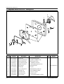
Exploded Views and Parts List
7-3 Exploded View & Parts List - Door Parts
4
6
9
8
7
3
2
5
10
1
Ref. No.
Parts No.
1
2
3
4
5
6
7
8
9
10
DE64-40045A
DE67-20029E
DE92-50037A
DE64-40103A
DE64-40124A
DE92-90138A
DE61-70057B
DE92-90052A
DE73-90018A
DE60-60021A
7-4
Description
DOOR-A
SCREEN-DOOR(B)
ASSY DOOR-E
DOOR-C
DOOR-KEY
ASSY-BRACKET SLIDER
SPRING-KEY
ASSY-HINGE-U
FERRITE
PIN-DOOR
Specification
PC-LEXAN141,RP-WH-01-K,310G,RE
TEMP,GLASS,T3.2XW313XL435,VITA
SILICON,BONDING
PBT-1500G,158G
NYLON#66-2411GF,5.1G
RE-909CG
HSWR,PI1.2,D5.8,L47
SBC1,T2.0
DB-867CPE,T4.1,W7.0,L1310
MSWR,ZPC3
Q'ty
Remarks
1
1
1
1
2
1
1
1
1
2
Samsung Electronics
Exploded Views and Parts List
7-4 Exploded View & Parts List - Control Parts
11
5
6
3
7
12
8
9
15
4
13
Ref. No.
1
Parts No.
14
2
Description
Specification
Q'ty
1
DE66-20025A
BUTTON-PUSH
PC-LEXAN#141,RP-WH-01-K,19G,RE
1
2
3
4
5
6
7
8
9
12
13
14
15
16
DE72-70051M
DE67-40027H
DE66-20041A
DE66-20026A
DE66-20042A
DE66-20080A
DE66-20024A
DE61-50072A
DE39-30091A
DE64-10038C
DE61-70076A
DE34-20030A
DE93-30066M
CONTROL-PANEL
WINDOW-DISPLAY
BUTTON-CANCEL
BUTTON-SELECT-L
BUTTON-SELECT-R
BUTTON-CLOCK
BUTTON-MORE
BRACKET-PANEL
WIRE LEAD-PCB(B)
KNOB-VOLUME
SPRING-BUTTON
SWITCH-VOLUME
ASSY CONTROL-BOX
PC(LEXAN#141),RP-WH-01-K,230G
ACRYL,SMOG,40G,AMFO
PC-LEXAN#141,RP-WH-01-K,6G,RE
PC-LEXAN#141,RP-WH-01-K,16G
PC-LEXAN#141,RP-WH-01-K,10G
PC-LEXAN#141,RP-WH-01-K,1G,RE
PC-LEXAN#141,RP-WH-01-K,7G,RE
SECC,T0.8,W107,L286.35
L60,RE-1280(SAW),AMFO
PC(LEXAN#141),WHT,5G,CIRCLE,PR
HSWR,PI0.6
4M17736
CE124CF(SAW),AMFO
1
1
2
1
1
1
1
1
1
1
2
1
1
Samsung Electronics
Remarks
7-5
Exploded Views and Parts List
7-5 Exploded View & Parts List - Casing Parts
8
7
9
11
4
6
10
1
Ref. No.
Parts No.
1
2
3
4
5
6
7
8
9
10
11
12
DE31-90020A
DE47-70028B
DE72-30014A
DE92-90212C
DE61-50192A
DE60-30016B
DE31-90019A
DE91-50031A
DE47-20044A
DE60-40026A
DE62-10014A
DE92-90079G
7-6
5
3
2
Description
BLADE-FAN
HEATER-CONVECTION
BUSH-GEAR MOTOR
ASSY-HEATER COVER
BRACKET-HEATER-B
NUT-FLANGE
BLADE-FAN
ASSY-CONV.MOTOR
THERMOSTAT
WASHER-PLAIN
INSULATION-TCO
ASSY-CASING
Specification
ALSTAR,T0.6,W250,L250
D8,230V6.1A,1400W,RE-1280
SWRM3,ID5,OD7,ZPC3
RE-1280,NEW,SYSTEM,VI
STS430,T0.8,W28.5,L65.4,RE-128
M4,MSWR10,FEFN
SECC,T0.6
AMM90-004AUEA,230V0.33A
PW-2N,150/60,BKT23.8MM
ID5.5,OD12,T1.0,SBC1
T2.0,W34,L26,YEL
RE-1270/1280,230V,NEW,SYSTEM,V
Q'ty
1
1
1
1
2
3
1
1
1
1
1
1
Remarks
BL-FAN/HEATER
Samsung Electronics
Exploded Views and Parts List
7-6 Parts List - Standard Parts
Parts No.
Description
DE60-10012A
DE60-10012A
DE60-10013A
DE60-10016A
DE60-10032A
DE60-10045A
DE60-10052A
DE60-10052A
DE60-10052A
DE60-10053A
DE60-10061A
DE60-10061A
DE60-10063A
DE60-10063A
DE60-10066A
DE60-10069A
DE60-10069A
DE60-10069A
DE60-10069A
DE60-10069A
DE60-10069A
DE60-10069A
DE60-10069A
DE60-10080A
DE60-10082H
DE60-10082H
DE60-10082H
DE60-10082H
DE60-10082H
DE60-10082H
DE60-10082H
DE60-10082H
DE60-10082H
DE60-10082H
DE60-10082H
DE60-10082H
DE60-20014A
DE60-20014A
DE60-30015A
DE60-30016A
DE60-30016A
DE60-30016A
DE60-10045A
DE60-10066A
DE60-10122A
DE60-10047A
DE60-10052A
DE60-10069A
DE60-10012A
DE60-10069A
DE60-10072A
DE60-10082H
DE60-10088A
SCREW-TAP TITE
SCREW-TAP TITE
SCREW-ASSY TAP
SCREW-ASSY MACHINE
SCREW-TH
SCREW-TAP PH
SCREW-TAP PH
SCREW-TAP PH
SCREW-TAP PH
SCREW-TAP PH
SCREW-TAP TH
SCREW-TAP TH
SCREW-TAP TH
SCREW-TAP TH
SCREW-TAP TH
SCREW-TAP TH
SCREW-TAP TH
SCREW-TAP TH
SCREW-TAP TH
SCREW-TAP TH
SCREW-TAP TH
SCREW-TAP TH
SCREW-TAP TH
SCREW-WASHER
SCREW-A
SCREW-A
SCREW-A
SCREW-A
SCREW-A
SCREW-A
SCREW-A
SCREW-A
SCREW-A
SCREW-A
SCREW-A
SCREW-A
BOLT-FLANGE
BOLT-FLANGE
NUT-FLANGE
NUT-FLANGE
NUT-FLANGE
NUT-FLANGE
SCREW-TAP PH
SCREW-TAP TH
SCREW-TAP TH
SCREW-TAP PH
SCREW-TAP PH
SCREW-TAP TH
SCREW-TAP TITE
SCREW-TAP TH
SCREW-TAP TH
SCREW-A
SCREW-TAP PH
Samsung Electronics
Specification
TH,+,3,M4,L10,SWR10,ZPC2,TOOTH
TH,+,3,M4,L10,SWR10,ZPC2,TOOTH
TH,2S,4,L12,MSWR3,ZPC3,FIBER
TH,4,L10,STS43
TH,+,M4,L8,STS304
PH,M3,L6,FEFZY
PH,M4,L8,FEFZY
PH,M4,L8,FEFZY
PH,M4,L8,FEFZY
PH,M4,L10,FEFZY
TH,M4,L8,STS
TH,M4,L8,STS
TH,M4,L12,FEFN
TH,M4,L12,FEFN
TH,M4,L8,FEFZY,2-SLOT
TH,M4,L10,FRFZY
TH,M4,L10,FRFZY
TH,M4,L10,FRFZY
TH,M4,L10,FRFZY
TH,M4,L10,FRFZY
TH,M4,L10,FRFZY
TH,M4,L10,FRFZY
TH,M4,L10,FRFZY
M5,L12,2S
2S-4X12,TOOTHED
2S-4X12,TOOTHED
2S-4X12,TOOTHED
2S-4X12,TOOTHED
2S-4X12,TOOTHED
2S-4X12,TOOTHED
2S-4X12,TOOTHED
2S-4X12,TOOTHED
2S-4X12,TOOTHED
2S-4X12,TOOTHED
2S-4X12,TOOTHED
2S-4X12,TOOTHED
M5,L10,MSWR3,FEFZY
M5,L10,MSWR3,FEFZY
M5,P0.8,MSWR10,FEFZY
M4,MSWR10
M4,MSWR10
M4,MSWR10
PH,M3,L6,FEFZY
TH,M4,L8,FEFZY,2-SLOT
TAP,TH,2-4X8,FE,FN
PH,M3,L16,FEFZY
PH,M4,L8,FEFZY
TH,M4,L10,FRFZY
TH,+,3,M4,L10,SWR10,ZPC2,TOOTH
TH,M4,L10,FRFZY
TH,M4,L16,FEFZY,2-SLOT
2S-4X12,TOOTHED
PH,M3,L8,FEFZY,PLAIN
Q'ty
Remarks
1
1
6
1
2
2
1
1
2
2
2
2
1
4
4
1
2
2
2
2
2
8
4
4
1
1
2
1
2
11
2
3
1
5
2
1
2
2
4
2
2
1
2
3
2
2
2
3
1
2
4
2
14
H.V.D
N/FILT
BASE-P
SENSOR
BAR-HL
TCO-MG
B/U-HI
FR-PAN
TCO-GR
BAR-MO
G/LAMP
PL-CEI
HI-LOW
OUT-PN
B/GE-M
A-C-AI
AIR-GU
B/HTR
B/LAMP
C/AD-L
C/AD-R
CASING
DAMPER
HVT
A-B-RE
A-REST
B-PLTE
B/HVC
B/U-HI
BACK-P
BD-LAT
CON-BX
MO-FAN
OUT-PN
SUP-MG
W-H-A
LOW-HI
UPP-HI
MGT
BR-HAN
GRIL-H
SENSOR
P/EART
FOOT
COV/B
7-7
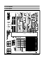
8. P.C.B Diagrams
8-1 P.C.B Diagrams
CON01
12V
12V(A)
F1
R12 10K-J
Q09
A539
12V(A)
F2
470-J
470-J
+
Q01
D882Y
ZD01 1W 5.1V
C18 0.1uF
R03 470-J
-20V
ZD02
0.5W 13V
D03
1N4148
C10 10uF
D05
1N4001
12V
5V
R08 10K-J
+
(A)
D04 1N4001
12V
5V
Q04
R1005
(A)
R06
5.1K-J
Q02
C815
BUZZER
ZD03
0.5W3.9V
R04
1K-J
R05
1K-J
12V
C07
0.1uF
R07
10K-J
2
1
(B)
C05
0.1uF
(B)
C06
0.1uF
R18
R17
100K-F
3.9K-J
3.9K-J
6
R19
3.9K-J
R14
10K-J
R13 3.9K-J
Q05
R1005
C09 27pF
C08 27pF
Q03
C815
3
Q10
C815
4
10K-J
5K-F
Q12 A539
R21
D07
1N4001
R09 1K-J
12V(A)
2K-J
POWER
RELAY
R23
C15 +
1uF
R22
R20
15 INT
B0 45
G0 34
G1 35
G2 36
G3 37
m
n
o
p
G4
G3
G2
G1
-20V
B1 46
l
100K
B2 47
k
100K
MICOM OPTION
B3 48
j
100K
B4 49
i
IC 1
3 VREF
B5 50
h
64 VCC
12 RESET
B6 51
g
62 OSC OUT
63 OSC IN
1 VSS
2 VASS
B7 52
f
6
1N4148
D15
H7 32
1N4148
D14
CH2
0
-2
-6
-4
CH2 gnd
-5V
CH1gnd
C14
332
CH1 5V
CH2 2V
C15
332
C17
332
F1
F2
A 200ms 2.21 V VERT
-354.00ms
CH2 MAX - 5.16V
C16
332
R33 R34 R35 R36
47K-J 47K-J 47K-J 47K-J
e
1N4148
D13
OPTION
H6 31
1N4148
D12
OPTION
OPTION
H5 30
41 G7
14 E1
1N4148
D11
START
OPTION
d
5
MIN+
CANCEL
H4 29
4
1N4148
D10
MIN-
OPTION
3
COMBI 2
(M+C)
OPTION
OPTION
c
2
COMBI 3
(G+C)
OPTION
b
1
GRILL
TIME
COOK
CLOCK
POWER
LEVEL
CONVECTION
COMBI1
(M+G)
A 200ms 2.21 V VERT
5V
P.C.B.-SUB
AUTO
DEFROST
H3 28
10
9
8
7
0V
CH1 5V
CH2 5V
CH2 MAX - 5.16V
CH1
AUTO
COOK
a
R29 3.9K-J
R30 3.9K-J
R31 3.9K-J
R32 3.9K-J
-20V
4
-5V
Pin 5
0V
V1
V1
Pin 4
-3V
5
CH1gnd
4
6
5V
0
CH2 gnd 2
T
H2 27
A4 8
A5 9
A6 10
A7 11
33
53
54
55
56
57
58
59
60
2 tones
4 tones
6
H1 26
1 tone
H0 25
23 C6
24 C7
16 E3
13 E0
5 A1
4 A0
17 C0
6 A2
7 A3
1
20 C3
16
21 C4
18 C1
4
22 C5
8
5
19 C2
14
13
12
11
9
6
2
3
3
IC2
Power Off
15
1K-F
1M-J
5V
C04
100uF
7805
VTG-REG
5V
R24
1M-J
Q07 R2005
R37
R38
Q06
R1005
+ C03
1000uF
R10
2K-J
R15
3.9K-J
C12
0.1uF
12V
2
0.1sec
0.6sec 0.4sec
0.6sec 0.4sec
MICOM
R01
R02
D01 1N4001
C01
470uF
+
-20V
R16
10K-J
D06 1N4001
+ C11
10uF
Q11
C815
DOOR S/W
CON03
THERMISTOR
INRUSH RELAY
GRILL RELAY
FAN RELAY
DAMPER RELAY
CONV.M RELAY
CONV.H RELAY
Power On
1. Beep tone
2. Stage change and
half time in Auto Weight
Defrost tone
3. Error and Finish Tone
SVM-4MS-13
C02
470uF
Q08
R1005
D02 1N4001
R11 3.9K-J
D08
1N4001
1K-J
10K-J
1K-J
R27
10K-J
1
R28
R25
ENCODER
SWITCH R26
5V
12V
5
MAIN
RELAY
Waveform of (A)
0V
Waveform of (A)
VCC (-5V )
Waveform of (B)
VCC (-5V)
ZD4
Turn off
V.F.DISPLAY
Samsung Electronics
8-1
0V
-5V DC
Waveform of (B)
0V
-5V DC
KA2657
+
P.C.B Diagrams
8-2 P.C.B Parts List
No.
Parts No.
Description
Specification
Q'ty
Remarks
P1
P2
P3
P3
P3
P4
P5
P6
P7
P8
P9
P10
P11
P12
P13
P14
P15
P16
P17
P18
P19
P20
P21
P22
P23
P24
P25
P25
P26
P27
P28
P29
P29
P30
P31
P32
P33
P34
P35
P36
P37
P38
P39
P40
P41
P42
P43
P44
P45
P46
P47
P48
P49
P50
P51
0502-000303
3406-001031
3501-000265
3501-000265
3501-000265
3501-000334
3711-000315
3711-000607
3711-000612
3711-001343
DE07-10052A
DE09-30158A
DE13-20016A
DE13-20017A
DE30-20016A
DE61-90034D
0401-001002
0402-001103
0403-000150
0403-000525
0501-000283
0501-000388
0504-001045
0504-001046
2001-000042
2001-000062
2001-000065
2001-000065
2001-000076
2001-000432
2001-000575
2001-000611
2001-000611
2004-000193
2004-000432
2004-001118
2201-000442
2201-000817
2202-000780
2401-000030
2401-000159
2401-000244
2401-000466
2401-000598
2401-001415
2802-000143
3404-001022
3711-000881
3711-000940
3711-000999
DE13-20009A
DE39-40113A
DE39-60001A
DE41-10108A
DE92-90093D
TR-POWER
SWITCH-ROTARY
RELAY-POWER
RELAY-POWER
RELAY-POWER
RELAY-REED
CONNECTOR-HEADER
CONNECTOR-HEADER
CONNECTOR-HEADER
CONNECTOR-HEADER
V.F.DISPLAY
IC-MCU
IC-VOLT REGU
IC-DRIVE
BUZZER
HOLDER-DIGITRON
DIODE-SWITCHING
DIODE-RECTIFIER
DIODE-ZENER
DIODE-ZENER
TR-SMALL SIGNAL
TR-SMALL SIGNAL
TR-DIGITAL
TR-DIGITAL
R-CARBON
R-CARBON
R-CARBON
R-CARBON
R-CARBON
R-CARBON
R-CARBON
R-CARBON
R-CARBON
R-METAL
R-METAL
R-METAL
C-CERAMIC,DISC
C-CERAMIC,DISC
C-CERAMIC,MLC-AXIAL
C-AL
C-AL
C-AL
C-AL
C-AL
C-AL
RESONATOR-CERAMIC
SWITCH-TACT
CONNECTOR-HEADER
CONNECTOR-HEADER
CONNECTOR-HEADER
IC
WIRE HARNESS-F
WIRE-SO COPPER
P.C.B-MAIN-SUB
ASSY-HEAT SINK
KSD882,NPN,1W,TO-126,TP,160-32
10V,1mA,DP24T,18.3mm
12V,-,16A,-,15mS,15mS
12V,-,16A,-,15mS,15mS
12V,-,16A,-,15mS,15mS
12V,1250VA,10A,-,10mS,5mS
1WALL,7P,1R,3.96mm,STRAIGHT,SN
BOX,11P,1R,2.50mm,ANGLE,SN
BOX,11P,1R,2.5mm,STRAIGHT,SN
NOWALL,1P,1R,3.4mm,STRAIGHT,AG
SVM-4MS13S,MWO,RE-1280
TMS73C91-C69416,DIP,RE-1280
KA7805A,TO-220AB,1A,0/125C
KID65003AP,DIP,16P,STICK,TR-AR
CBE2220BA,STICK
PP(JI350),BLK
1N4148M,100V,200mA,DO-34,TP
1T4,400V,1A,TS-1,TP
1N4743A,13V,5%,1W,DO-41,TP
1N4733A,5.1V,5%,1W,DO-41,TP
KSA539,PNP,400mW,TO-92,TP,120KSC815,NPN,400mW,TO-92,BK,120KRC119M,NPN,400MW,4.7K/10K,TO-92M,TP
KRA119M,PNP,400MW,4.7K/10K,TO-92M,TP
1KOHM,5%,1/4W,AA,TP,2.4X6.4MM
470OHM,5%,1/4W,AA,TP,2.4X6.4MM
10KOHM,5%,1/4W,AA,TP,2.4X6.4MM
10KOHM,5%,1/4W,AA,TP,2.4X6.4MM
47KOHM,5%,1/4W,AA,TP,2.4X6.4MM
1MOHM,5%,1/4W,AA,TP,2.4X6.4MM
2KOHM,5%,1/4W,AA,TP,2.4X6.4MM
3.9KOHM,5%,1/4W,AA,TP,2.4X6.4MM
3.9KOHM,5%,1/4W,AA,TP,2.4X6.4MM
100Kohm,1%,1/4W,AA,TP,2.4x6.4m
1Kohm,1%,1/4W,AA,TP,2.4x6.4mm
5Kohm,1%,1/4W,AA,TP,2.4x6.4mm
3.3nF,10%,50V,X7R,-,-,08x5.0
22pF,79.8,50V,Y5V,TP,4x4,5
100nF,+80-20%,50V,Y5V,TP,3.5x1
22uF,20%,25V,GP,TP,5x11,5
1000uF,20%,25V,GP,-,13x25x7.5m
100uF,20%,10V,GP,TP,6.3x7,5
10uF,20%,35V,GP,TP,5x7,5
1uF,20%,50V,GP,TP,4x7,5
470uF,20%,35V,GP,TP,10x20,5
4.19MHz,0.5%,TP,10.0x5.0x7.5mm
15V,20mA,130°æ40gf,6x6x5mm,SPS
BOX,3P,1R,2.5mm,STRAIGHT,SN
BOX,4P,1R,2.5mm,STRAIGHT,SN
BOX,5P,1R,2.5mm,STRAIGHT,SN
KA7533,DIP
110/220V,60HZ,MX200TCC,130MMX3
PI0.6,SN,T,52MM,TAPING_WIRE
FR-1,T1.6,W197,L327,RE-1280
JVM-190K,A-TYPE
1
1
2
2
2
1
1
1
1
1
1
1
1
1
1
1
7
7
1
1
2
2
4
1
5
3
5
2
4
2
2
5
5
1
1
1
4
2
5
1
1
1
2
1
2
1
14
2
1
1
1
1
35
1
1
Q01
ECD1
CONV-H,CONV-M
GRILL,INRUSH
MAIN,POWER
RELAY
CON04
CON06
CON02
GND
VFD
MICOM
IC04
IC02
BUZZER
D03,D09,D10,D11~D14
D01,D02,D04,D05~D08
ZD02
ZD01
Q09,Q10
Q04,Q05
Q02,Q03,Q06,Q08
Q07
R04,R05,R09,R27,R28
R01,R02,R03
R06,R07,R08,R12,R14
R16,R21
R33,R34,R35,R36
R24,R25
R10,R23
R11,R13,R15,R17,R18
R20,R29,R30,R31,R32
R19
R26
R22
C14,C15,C16,C17
C08,C09
C05,C06,C07,C12,C19
C18
C03
C04
C10,C11
C13
C01,C02
XTAL
SW01~SW14
CON05,CON07
CON03
CON01
IC03
J01~J35
PCB
-
Samsung Electronics
8-2
9. Schematic Diagram & Wiring Diagram
9-1 Schematic Diagram
CONNECTOR "A"
NOISE FILTER
CONNECTOR "B"
(BLK)
(BLK)
MAIN RELAY
SEC. S/W RY.
(BLK)
(WHT)
(BLU)
(ORG)
MONITOR
FUSE
C3
2200pF
N
(BLU)
DAMPER RY.
(BLK)
(ORG)
0V 50Hz
GLE
ASE
FUSE
15A
L
C2
2200pF
MGT
T.C.O.
S/W
(ORG)
(WHT)
0.15uF
CAP.
FM
0.15uF
(ORG) CAP.
MONITOR
SWITCH
DM
DAMPER
MOTOR
(WHT)
RESISTOR
H.V.D
SM
CM
(BLU)
GRILL
T.C.O.
(ORG)
(ORG)
(10W
15ohm)
(BRN, YEL)
L
GRILL
HEATER
(BRN)
(BLU)
CONV.
HEATER
RELAY
INRUSH
RELAY
T/T
MOTOR
LAMP
(WHT)
(YEL)
(BRN)
TM
(RED)
FAN
MOTOR
(ORG)
(BLU,RED)
(COM)
CONV.
MOTOR
RELAY
(10W 30ohm)
(BLK)
(NC)
(NO)
DAMPER
SWITCH
C1
500K
0.1uF OHM
(Y/G)
(GRY)
(BLU)
FAN
MOTOR
RELAY
GRILL
RELAY
(NC)
(NO)
1.3mH
SURGE
RESISTOR
(RED)
(BLU)
LVT
(YEL)
(BLK)
CONDITION OF OVEN
DOOR OPENED
PLUG IN
CONV.
MOTOR
SPIT
MOTOR
(GRY,BLU)
CONV.
HEATER
H.V.FUSE
(0.8A)
(RED)
(RED)
H.V.C.
(1.13uF)
(RED)
CONV.
T.C.O.
(BLU,BLK)
F
H.V.TRANS
F
(RED)
(WHT,BLU)
(RED)
(RED)
MAGNETRON
(RED)
PRIMARY SWITCH
CONNECTOR "C"
* Switches and relays status according to each condition
Condition
DOOR
OPEN
DOOR
CLOSE
MICROWAVE
GRILL
CONVEC
-TION
MWO+
GRILL
MWO+
CONV.
GRILL+
CONV.
PRI.S/W
OPEN
CLOSE
CLOSE
CLOSE
CLOSE
CLOSE
CLOSE
CLOSE
MON.S/W
CLOSE
OPEN
OPEN
OPEN
OPEN
OPEN
OPEN
OPEN
MAIN RY
ON
OFF
ON
ON
ON
ON
ON
ON
SEC.S/W RY
OFF
OFF
ON
OFF
OFF
ON
ON
OFF
GRILL RY
OFF
OFF
OFF
ON
OFF
ON
OFF
ON
CONV. HEA.RY
OFF
OFF
OFF
OFF
ON
OFF
ON
ON
FAN.MTR.RY
OFF
OFF
ON
ON
ON
ON
ON
ON
DAMPER RY
OFF
OFF
OFF
ON
ON
ON
ON
ON
CONV.MTR.RY
OFF
OFF
OFF
ON
ON
ON
ON
ON
ITEM
9-1
Samsung Electronics
Schematic Diagram & Wiring Diagram
(BLK)
(GRY)
(BLU)
MAIN RY.
SEC. S/W RY.
(WHT)
(ORG)
INRUSH RY.
.
OVEN THERMISTOR
GRILL RY.
(BUL)
9-2 Wiring Diagram
(ORG)
(RED)
SYMBOL
COLOR
Y/G
YELLOW//GREEN
BLK
BLACK
WHT
WHITE
BLU
BLUE
BRN
BROWN
GRY
GRAY
YEL
YELLOW
ORG
ORANGE
RED
RED
DAMPER
MOTOR
RELAY
FAN MOTOR
RELAY
CON 4
ORG
: PARTS LINE
(BRN)
CON. MOTOR RY.
DOOR S/W
(YEL)
CONV. HEA.RY.
: GROUND
(YEL)
GRY
ORG BLK
(RED)
: PCB PATTERN LINE
L.V.TRANS
SECONDARY
(BLU,RED) :W-H-A=BLU , W-H-B=RED
VOLTAGE
CON 1
ORG
ORG
RED
BRN
ORG
ORG
RED
RED
BLU
DOOR SENSING SWITCH
PRIMARY SWITCH
MONITOR SWITCH
MAGNETRON
HIGH VOLTAGE
DIODE
TO CHASSIS
FA
F
HIGH VOLTAGE CAPACITOR
RED
H.V.FUSE
WHT
RED
RED
SYMBOL COLOR
ORG
ORANGE
WHT
WHITE
BLK
BLACK
RED
RED
YEL
YELLOW
HIGH VOLTAGE
TRANSFORMER
Samsung Electronics
9-2