1
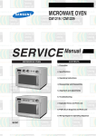
MICROWAVE OVEN
CE305CF
SERVICE
Manual
CONTENTS
MICROWAVE OVEN
1. Precaution
2. Specifications
3. Operating Instructions
4. Disassembly and Reassembly
5. Alignment and Adjustments
6. Troubleshooting
7. Exploded Views and Parts List
8. PCB Diagrams
9. Schematic Diagrams
HAD ELECTR
1. Precaution
Follow these special safety precautions. Although the microwave oven is completely safe during ordinary
use, repair work can be extremely hazardous due to possible exposure to microwave radiation, as well as
potentially lethal high voltages and currents.
1-1 Safety precautions (
)
1. All repairs should be done in accordance
with the procedures described in this
manual. This product complies with
Federal Performance Standard 21 CFR
Subchapter J (DHHS).
2. Microwave emission check should be
performed to prior to servicing if the oven is
operative.
3. If the oven operates with the door open :
Instruct the user not to operate the oven and
contact the manufacturer and the center for
devices and radiological health immediatly.
4. Notify the Central Service Center if the
microwave leakage exceeds 5 mW/cm2
5. Check all grounds.
6. Do not power the MWO from a "2-prong"
AC cord. Be sure that all of the built-in
protective devices are replaced. Restore any
missing protective shields.
7. When reinstalling the chassis and its
assemblies, be sure to restore all protective
devices, including: nonmetallic control
knobs and compartment covers.
8. Make sure that there are no cabinet openings
through which people--particularly
children--might insert objects and contact
dangerous voltages. Examples: Lamp hole,
ventilation slots.
9. Inform the manufacturer of any oven found
to have emmission in excess of 5 mW/cm2,
Make repairs to bring the unit into
compliance at no cost to owner and try to
determine cause.
Instruct owner not to use oven until it has
been brought into compliance.
CENTRAL SERVICE CENTER
10. Service technicians should remove their
watches while repairing an MWO.
Samsung Electronics
11. To avoid any possible radiation hazard,
replace parts in accordance with the wiring
diagram. Also, use only the exact
replacements for the following parts:
Primary and secondary interlock switches,
interlock monitor switch.
12. If the fuse is blown by the Interlock Monitor
Switch: Replace all of the following at the
same time: Primary, door sensing switch
and power relay, as well as the Interlock
Monitor Switch. The correct adjustment of
these switches is described elsewhere in this
manual. Make sure that the fuse has the
correct rating for the particular model being
repaired.
13. Design Alteration Warning:
Use exact replacement parts only, i.e.,
only those that are specified in the
drawings and parts lists of this manual.
This is especially important for the
Interlock switches, described above.
Never alter or add to the mechanical or
electrical design of the MWO. Any design
changes or additions will void the
manufacturer's warranty.10.Always unplug
the unit's AC power cord from the AC
power source before attempting to
remove or reinstall any component or
assembly.
14. Never defeat any of the B+ voltage
interlocks. Do not apply AC power to the
unit (or any of its assemblies) unless all
solid-state heat sinks are correctly installed.
15. Some semiconductor ("solid state") devices
are easily damaged by static electricity. Such
components are called Electrostatically
Sensitive Devices (ESDs). Examples include
integrated circuits and field-effect
transistors.
Immediately before handling any
semiconductor components or assemblies,
drain the electrostatic charge from your
body by touching a known earth ground.
16. Always connect a test instrument's ground
lead to the instrument chassis ground before
connecting the positive lead; always remove
the instrument's ground lead last.
1-1
Pretaution
1-2 Special Servicing Precautions (Continued)
17. When checking the continuity of the
switches or transformer, always make sure
that the power is OFF, and one of the lead
wires is disconnected.
18. Components that are critical for safety are
indicated in the circuit diagram by
shading,
or
.
19. Use replacement components that have the
same ratings, especially for flame resistance
and dielectric strength specifications. A
replacement part that does not have the
same safety characteristics as the original
might create shock, fire or other hazards.
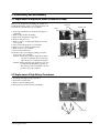
1-3 Special High Voltage Precautions
1. High Voltage Warning
Do not attempt to measureany of the high
voltages--this includes the filament voltage
of the magnetron. High voltage is present
during any cook cycle.
Before touching any components or wiring,
always unplug the oven and discharge the
high voltage capacitor (See Figure 1-1)
2. The high-voltage capacitor remains charged
about 30 seconds after disconnection. Short
the negative terminal of the high-voltage
capacitor to the oven chassis. (Use a
screwdriver.)
3. High voltage is maintained within specified
limits by close-tolerance, safety-related
components and adjustments. If the high
voltage exceeds the specified limits, check
each of the special components.
=> : Touch chassis side first then short to the high voltage
capacitor terminal by using a screwdriver or jumper
wire.
PRECAUTION
There exists HIGH VOLTAGE ELECTRICITY with high
current capabilities in the circuits of the HIGH VOLTAGE
TRANSFORMER secondary and filament terminals. It is
extremely dangerous to work on or near these circuits
with the oven energized.
DO NOT measure the voltage in the high voltage circuit
including filament voltage of magnetron.
1-2
PRECAUTION
Never touch any circuit wiring with your hand nor with an
insulated tool during operation.
PRECAUTION
Servicemen should remove their watches whenever
working close to or replacing the magnetron.
Samsung Electronics
2. Specifications
2-1 Table of Specifications
ITEM
MODEL
CE305CF
TIMER
99 MINUTES 90 SECONDS
POWER SOURCE
220-230V/50HZ, AC
POWER CONSUMPTION
MAXIMUM POWER
: 2950W
MICROWAVE
: 1500W
GRILL (HEATING ELEMENT)
: 1400W
CONVECTION (HEATING ELEMENT) : 1450W
OUTPUT POWER
90W/900W - 10 LEVELS (IEC-705)
OPERATING FREQUENCY
2,450MHz
MAGNETRON
OM75P(31)
COOLING METHOD
COOLING FAN MOTOR
OUTSIDE DIMENSIONS
547(W) x 339(H) x 487(D)
NET WEIGHT
25 Kg
SHIPPING WEIGHT
29 Kg
Samsung Electronics
2-1
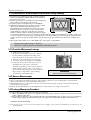
3. Operating Instructions
3-1 Control Panel
OVEN/ °C
MICROWAVE
MICROWAVE MODE SELECTION
CONVECTION MODE/
TEMPERATURE SELECTION
POWER LEVEL
GRILL
GRILL MODE SELECTION
MICROWAVE POWER
LEVEL SELECTION
MW+OVEN
AUTO DEFROST
COMBINED MODE SELECTION
(MICROWAVE+CONVECTION)
AUTO REHEAT
FEATURE SELECTION
MW+GRILL
COMBINED MODE SELECTION
(MICROWAVE+GRILL)
CLOCK
CLOCK SETTING
AUTO REHEAT/COOK
1. PLATED MEAL
2. CANNED FOOD
3. CASSEROLE / STEW
4. SOUP / SAUCE
5. BOILED POTATOES
6.FRESH VEGETABLES
7. FISH
8. ROAST BEEF
9. ROAST PORK
10.ROAST CHICKEN
AUTO COOK
AUTO COOK
FEATURE SELECTION
MEMORY
M
MEMORY COOK
FEATURE SELECTION
PLUS / MIN+
MINUS / MIN-
COOKING TIME
ADJUSTMENT BUTTONS
INSTANT COOK SELECTION
RICE /
PASTA
QUICHE
DRINKS
1. PIZZA
2. OVEN CHIPS
3. PIE/QUICHE
HOLD
TIMER
STANDING TIME
SETTING
CRUSTY
Hr
Min
Dish
10 Min
1 Min
1k g
10S
0.1 kg
CRUSTY COOK
SELECTION
TIME SETTING,
WEIGHT SELECTION AND
SERVING SELECTION
START BUTTON
STOP/CANEL BUTTON
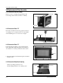
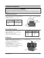
3-2 Features & External Views
Door
Ventilation Holes
Light
Safety Interlock Holes
Control Panel
Door Latches
Open Door Push Button
Guide Roller
339mm
Glass Plate
225mm
547mm
3-1
487mm
Samsung Electronics
4. Disassembly and Reassembly
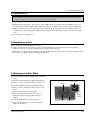
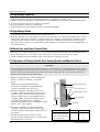
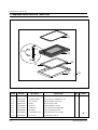
4-1 Replacement of Magnetron, Motor Assembly and Lamp
Remove the magnetron including the shield case,
permanent magnet, choke coils and capacitors (all
of which are contained in one assembly).
1. Disconnect all lead wires from the magnetron
and lamp.
2. Remove the bracket mounting.
3.Remove the magnetron supporter
4. Remove the air cover.
5. Remove screws securing the magnetron to the
wave guide.
6. Take out the magnetron very carefully.
7. Remove screws from the back panel.
8.Remove the assy noise filter.
9. Take out the fan motor.
10. Remove the oven lamp by pulling out from
hole of air cover carefully.
NOTE1: When removing the magnetron, make
sure that its antenna does not hit any
adjacent parts, or it may be damaged.
NOTE2: When replacing the magnetron, be sure
to remount the magnetron gasket in
the correct position and make sure the
gasket is in good condition.
Cover Air
Thermo S/W
Lamp
Fan Motor
Magnetron H. V. Trans
H. V. Capacitor
Screw
4-2 Replacement of High Voltage Transformer
1. Discharge the high voltage capacitor.
2. Disconnect all the leads.
3. Remove the mounting bolts.
4. Reconnect the leads correctly and firmly.
H. V. Trans
Screws
Samsung Electronics
4-1
Disassembly and Reassembly
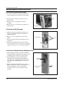
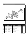
4-3 Replacement of Door Assembly
4-3-1 Removal of Door Assembly
Remove screws securing the upper hinge and
lower hinge. Then remove the door assembly.
Upper Hinge
Screw
Lower Hinge
Screw
4-3-2 Removal of Door "C"
Insert flat screwdriver into the gap between Door
"A" and Door "C" to remove Door "C". Be careful
when handling Door "C" because it is fragile.
Door "A"
Door "C"
4-3-3 Removal of Door "E"
Following the procedure as shown in the figure,
insert and bend a thin metal plate between Door
"E" and Door "A" until you hear the 'tick' sound.
Door "E"
1. Insertion depth of the thin metal plate should be
0.5mm or less.
4-3-4 Removal of Key Door & Spring
Remove pin hinge from Door "E"
Detach spring from Door "E" and key door.
Door "E"
Spring
Key Door
4-2
Samsung Electronics
Disassembly and Reassembly
4-3-5 Reassembly Test
After replacement of the defective component parts of the door, reassemble it and follow the instructions below for proper
installation and adjustment so as to prevent an excessive microwave leakage.
1. When mounting the door to the oven, be sure to adjust the door parallel to the bottom line of the oven
face plate by moving the upper hinge and lower hinge in the direction necessary for proper alignment.
2. Adjust so that the door has no play between the inner door surface and oven front surface. If the door
assembly is not mounted properly, microwave energy may leak from the space between the door and
oven.
3. Do the microwave leakage test.
4-4 Replacement of Fuse
1. Disconnect the oven from the power source.
2. When 15A fuse blows out by the operation of interlock monitor switch failure, replace the primary
interlock switch, door sensing switch, monitor switch and power relay.
3. When the above three switches operate properly, check if any other part such as the control circuit board,
blower motor or high voltage transformer is defective.
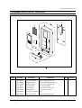
4-5 Replacement of Drive Motor
1. Take out the glass tray and guide roller from the
cavity.
2. Turn the oven upside down to replace the drive motor.
3. Remove a screw securing the drive motor cover.
Drive Motor
Screw
4. Disconnect all the lead wires from the drive motor.
5. Remove screws securing the drive motor to the
cavity.
6. Remove the drive motor and coupler.
7. When replacing the drive motor, be sure to
remount it in the correct position with the
coupler.
8. Connect all the leads to the drive motor.
Thermo
Switch
Drive Motor Cover
Base Plate
9. Screw the drive motor cover to the base plate
with a screw driver.
Samsung Electronics
4-3
Disassembly and Reassembly
4-6 Replacement of Control Circuit Board
4-6-1 Removal of Control Box Assembly
1. Be sure to ground any static electric charge in
your body and never touch the control circuit.
2. Disconnect the connectors from the control
circuit board.
Screw
3. Remove screws securing the control box
assembly.
4. Remove the screw securing the ground tail of
the keyboard.
Control Box
4-6-2 Removal of P.C.B Assembly
1. Pull the lever end of the plastic fastener and
remove the Flexible Printed Circuit(FPC) of
membrane panel.
2. Remove screws securing the control circuit
board.
FPC Connector
Screw
3. Lift up the control circuit board from the Ass'y
control box.
4. When reconnecting the FPC connector, make
sure that the holes on the connector are properly
engaged with the hooks on the Plastic Fastener.
4-6-3 Removal of Window Display & Membrane Panel
1. Window display should not be disassembled as
its mounting tabs will be broken. If repair work
is difficult, replace with Ass'y control panel.
2. The membrane key board is attached to the
escutcheon base with doublefaced adhesive
tape. Therefore, applying hot air such as using
of hair dryer is recommended for smoother
removal.
3. When installing new membrane key board,
make sure that the surface of escutcheon base is
cleaned sufficiently so that any problems
(shorted contacts or uneven surface) can be
avoided.
4-4
Window
Display
Membrane
Panel
Samsung Electronics
5. Alignment and Adjustments
PRECAUTION
1. High voltage is present at the high voltage terminals during any cook cycle.
2. It is neither necessary nor advisable to attempt measurement of the high voltage.
3. Before touching any oven components or wiring, always unplug the oven from its power source and discharge the high voltage
capacitor.
5-1 High Voltage Transformer
1. Remove connectors from the transformer terminals
and check continuity.
2. Normal resistance readings are as follows:
MODEL
Secondary
Filament
Primary
Filament Terminals
CE305CF
94Ω ± 10%
Shows Continuity
1.7Ω ± 10%
(Room temperature = 20˚C)
Primary
Terminals
5-2 Low Voltage Transformer
1. The low voltage transformer is located on the
control circuit board.
2. Remove the low voltage transformer from the
PCB Ass'y and check continuity.
3. Normal resistor reading is shown in the table.
Terminals
1~2(Input)
3~4(Output)
5~6(Output)
Resistance
195.4Ω
1.50Ω
0.73Ω
5-3 Magnetron
Continuity checks can indicate only an open
filament or a shorted magnetron. To diagnose an
open filament or shorted magnetron :
1. Isolate the magnetron from the circuit by
disconnecting its leads.
2. A continuity check across the magnetron filament
terminals should indicate one ohm or less.
3. A continuity check between each filament terminal
and magnetron case should read open.
Magnetron Antenna
Gasket Plate
Cooling Fins
Samsung Electronics
5-1
Alignment and Adjustments
5-4 High Voltage Capacitor
1. Check continuity of the capacitor with the meter set at the highest resistance scale.
2. Once the capacitor is charged, a normal capacitor shows continuity for a short time, and then indicates 9MΩ.
3. A shorted capacitor will show continuous continuity.
4. An open capacitor will show constant 9MΩ.
5. Resistance between each terminal and chassis should read infinite.
5-5 High Voltage Diode
1. Isolate the diode from the circuit by disconnecting its leads.
2. With the ohm-meter set at the highest resistance scale, measure across the diode terminals. Reverse the
meter leads and read the resistance. A meter with 6V, 9V or higher voltage batteries should be used to
check the front-to back resistance of the diode (otherwise an infinite resistance may be read in both
directions). The resistance of a normal diode will be infinite in one direction and several hundred KΩ in
the other direction.
5-6 Main Relay and Power Control Relay
1. The relays are located on the PCB Ass'y. Isolate them from the main circuit by disconnecting the leads.
2. Operate the microwave oven with a water load in the oven. Set the power level set to high.
3. Check continuity between terminals of the relays after the start pad is pressed.
5-7 Adjustment of Primary Switch, Door Sensing Switch and Monitor Switch
Precaution
For continued protection against radiation hazard, replace parts in accordance with the wiring diagram and be sure to use the
correct part number for the following switches: Primary and door sensing switches, and the interlock monitor switch (replace all
together). Then follow the adjustment procedures below. After repair and adjustment, be sure to check the continuity of all
interlock switches and the interlock monitor switch.
1. When mounting Primary switch and Interlock
Monitor switch to Latch Body, consult the
figure.
Primary Interlock S/W
NOTE:No specific adjustment during
installation of Primary switch and Monitor
switch to the latch body is necessary.
2. When mounting the Latch Body to the oven
assembly, adjust the Latch Body by moving it so
that the oven door will not have any play in it.
Check for play in the door by pulling the door
assembly. Make sure that the latch keys move
smoothly after adjustment is completed.
Completely tighten the screws holding the Latch
Body to the oven assembly.
3. Reconnect to Monitor switch and check the
continuity of the monitor circuit and all latch
switches again by following the components test
procedures.
4. Confirm that the gap between the switch
housing and the switch actuator is no more than
0.5mm when door is closed.
5-2
Lever Switch(A)
Door Sensing S/W
Interlock Monitor S/W
Lever Switch(B)
Body Latch
Key Door
Primary switch
Monitor switch (COM-NC)
Monitor switch (COM-NO)
Door Sensing switch
Door Open
∞
0
∞
∞
Door Closed
0
∞
0
0
Samsung Electronics
Alignment and Adjustments
5-8 Output Power of Magnetron
CAUTION
MICROWAVE RADIATION
PERSONNEL SHOULD NOT ALLOW EXPOSURE TO MICROWAVE RADIATION FROM MICROWAVE GENERATOR OR OTHER PARTS
CONDUCTING MICROWAVE ENERGY.
The output power of the magnetron can be measured by performing a water temperature rise test.
Equipment needed :
* Two 1-liter cylindrical borosilicate glass vessel (Outside diameter 190 mm)
* One glass thermometer with mercury column
NOTE: Check line voltage under load. Low voltage will lower the magnetron output. Make all temperature
and time tests with accurate equipment.
1. Fill the one liter glass vessel with water.
2. Stir water in glass vessel with thermometer, and record glass vessel's temperature ("T1", 10±1˚C).
3. After moving the water into another glass vessel, place it in the center of the cooking tray. Set the oven to high
power and operate for 48seconds exactly. (1.5 seconds included as a holding time of magnetron oscillation:)
4. When heating is finished, stir the water again with the thermometer and measure the temperature ("T2").
5. Subtract T1 from T2. This will give you the water temperature rise. (∆T)
6. The output power is obtained by the following formula;
Output Power =
4.187 x 1000 x ∆T+0.88xMcx(T2-T0)
46.5
46.5: Heating Time (sec)
4.187 : Coefficient for Water
1000 : Water (cc)
∆T : Temperature Rise (T2-T1)
Mc : Cylindrical borosilicate glass weight
To : Room temperature.
7. Normal temperature rise for this model is 9˚C to 11˚C at 'HIGH'.
NOTE 1: Variations or errors in the test procedure will cause a variance in the temperature rise.
Additional power test should be made if temperature rise is marginal.
NOTE 2: Output power in watts is computed by multiplying the temperature rise (step 5) by a factor of 90
times the of centigrade temperature.
5-9 Microwave Heat Distribution - Heat Evenness
The microwave heat distribution can be checked indirectly by measuring the water temperature rise at
certain positions in the oven:
1. Prepare five beakers made of 'Pyrex', having 100 milliliters capacity each.
2. Measure exactly 100milliliters off water load with a measuring cylinder, and pour into each beaker.
3. Measure the temperature of each water load. (Readings shall be taken to the first place of decimals.)
4. Put each beaker in place on the cooking tray as illustrated in figure below. Start heating.
5. After heating for 2 minutes, measure the water temperature in each beaker.
6. Microwave heat distribution rate can be calculated as follows:
Heat Distribution =
Minimum
Temperature Rise
Maximum
Temperature Rise
D
X 100(%)
Beaker
D
The result should exceed 65%.
D/4
D/4
D/4
D/4
Samsung Electronics
Cooking Tray
5-3
Alignment and Adjustments
5-10 Procedure for Measurement of Microwave Energy Leakage
1) Pour 275±15cc of 20±5˚C(68±9˚F) water in a beaker
which is graduated to 600cc, and place the beaker in
the center of the oven.
2) Start to operate the oven and measure the leakage by
using a microwave energy survey meter.
3) Set survey meter with dual ranges to 2,450MHz.
4) When measuring the leakage, always use the 2 inch
spacer cone with the probe. Hold the probe
perpendicular to the cabinet door. Place the spacer
cone of the probe on the door and/or cabinet door
seam and move along the seam, the door viewing
window and the exhaust openings moving the probe
in a clockwise direction at a rate of 1 inch/sec. If the leakage testing of the cabinet door seam is taken near
a corner of the door, keep the probe perpendicular to the areas making sure that the probe end at the base
of the cone does not get closer than 5cm to any metal. If it gets closer than 5cm, erroneous readings may
result.
5) Measured leakage must be less than 4mW/cm2, after repair or adjustment.
Maximum allowable leakage is 5mW/cm2.
4mW/cm2 is used to allow for measurement and meter accuracy
5-11 Check for Microwave Leakage
1. Remove the outer panel.
2. Pour 275±15cc of 20±5˚C(68±9˚F) water in a
beaker which is graduated to 600cc, and
place the beaker in the center of the oven.
3. Start the oven at the highest power level.
4. Set survey meter dual ranges to 2,450MHz.
5. Using the survey meter and spacer cone as
described above, measure arnear the
opening of magnetron, the surface of the air
guide and the surface of the wave guide as
shown in the following photo.( but avoid the
high voltage components.) The neading
should be less than 4mW/cm2.
WARNING
AVOID THE HIGH VOLTAGE COMPONENTS.
5-12. Note on Measurement
1) Do not exceed the limited scale.
2) The test probe must be held on the grip of the handle, otherwise a false reading may result when the
operator's hand is between the handle and the probe.
3) When high leakage is suspected, do not move the probe horizontally along the oven surface; this may
cause damage to the probe.
4) Follow the recommendation of the manufacturer of the microwave energy survey meter.
5-13 Leakage Measuring Procedure
5-13-1 Record keeping and notification after measurement
1) After adjustment and repair of a radiarion preventing device, make a repair record for the measured
values, and keep the data.
2) If the radiation leakage is more than 4 mW/cm2 after determining that all parts are in good condition,
functioning properly and the identical parts are replaced as listed in this manual notift that fact to ;
CENTRAL SERVICE CENTER
5-13-2 At least once a year have the microwave energy survey meter checked for accuracy by its
manufacturer.
5-4
Samsung Electronics
6. Troubleshooting
PRECAUTION
1. CHECK GROUNDING BEFORE CHECKING FOR TROUBLE.
2. BE CAREFUL OF THE HIGH VOLTAGE CIRCUIT.
3. DISCHARGE THE HIGH VOLTAGE CAPACITOR.
4. WHEN CHECKING THE CONTINUITY OF THE SWITCHES OR TRANSFORMER, DISCONNECT ONE LEAD WIRE FROM THESE
PARTS AND THEN CHECK CONTINUITY WITHOUT THE POWER SOURCE ON. TO DO OTHERWISE MAY RESULT IN A FALSE
READING OR DAMAGE TO YOUR METER.
5. DO NOT TOUCH ANY PART OF THE CIRCUIT OR THE CONTROL CIRCUIT BOARD, SINCE STATIC DISCHARGE MAY DAMAGE IT.
ALWAYS TOUCH GROUND WHILE WORKING ON IT TO DISCHARGE ANY STATIC CHARGE BUILT UP.
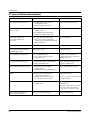
6-1 Electrical Malfunction
SYMPTOM
CAUSE
CORRECTIONS
Oven is dead.
Fuse is OK.
No display and no operation at all.
1. Open or loose lead wire harness
2. Open thermal cutout (Magnetron)
3. Open low voltage transformer
4. Defective Ass'y PCB
Check fan motor when thermal cutout is defective.
No display and no operation at all.
Fuse is blown.
1. Shorted lead wire harness
2. Defective primary latch switch (NOTE 1)
3. Defective monitor switch (NOTE1)
4. Shorted HVCapacitor
5. Shorted HVTransformer (NOTE2)
Check adjustment of primary, interlock monitor,
power relay, door sensing switch.
Check Ass'y PCB when LVT is defective.
NOTE 1: All of these switches must be replaced at the same time.
(refer to adjustment instructions)
Check continuity of power relay contacts and if it has continuity, replace power
relay also.
NOTE 2: When HVTransformer is replaced, check diode and magnetron also.
Oven does not accept
key input (Program)
Timer starts countdown but no
microwave oscillation.
(No heat while oven lamp and
fan motor turn on.)
Samsung Electronics
1. Key input is not in-Sequence
2. Open or loose connection of membrane
key pad to Ass'y PCB
3. Shorted or open membrane panel
4. Defective Ass'y PCB
Refer to operation procedure.
1. Off-alignment of latch switches
2. Open or loose connection of high voltage
circuit especially magnetron filament
circuit
NOTE: Large contact resistance will bring
lower magnetron filament voltage and
cause magnetron to lower output and/or
intermittent oscillation.
3. Defective high voltage components
H.V.Transformer
H.V.Capacitor
H.V.Diode,H.V.Fuse
Magnetron
4. Open or loose wiring of power relay
5. Defective primary latch switch
6. Defective power relay or Ass'y PCB
Adjust door and latch switches.
Replace PCB main.
Check high voltage component according to
component test procedure and replace if it is
defective.
Replace PCB main.
6-1
Troubleshooting
6-1 Electrical Malfunction(continued)
SYMPTOM
CAUSE
CORRECTIONS
Oven lamp and fan motor turn on
1. Misadjustment or loose wiring
of primary latch switch
2. Defective primary latch switch
Adjust door and latch switches.
Oven can program but timer
does not start.
1. Open or loose wiring of secondary
interlock switch
2. Off-alignment of primary interlock
3. Defective secondary interlock S/W
Adjust door and interlock switches.
Microwave output is low;.
Oven takes longer time to
cook food.
1. Decrease in power source voltage.
2. Open or loose wiring of magnetron
filament circuit. (Intermittent oscillation))
3. Aging of magnetron
Consult electrician.
Fan motor turns on when plugged in
Loose wiring of door sensing switch
Check wire of door sensing switch.
Oven does not operate and return
to the plugged in mode.
Defective Ass'y PCB
Replace PCB main.
Loud buzzing noise can be heard.
1. Loose fan and fan motor
2. Loose screws on H.V.Transformer
3. Shorted H.V.Diode
Tighten screws of fan motor.
Tighten screws of H.V.Transformer.
Replace H.V.Diode.
Turntable motor does not rotate.
1. Open or loose wiring of turntable motor.
2. Defective turntable motor.
Check the wire of turntable motor
Replace turntable motor.
Oven stops operation during cooking
1. Open or loose wiring of primary
interlock switch
2. Operation of thermal cutout(Magnetron)
Adjust door and latch switches.
Sparks
1. Metallic ware or cooking dishes
touching on the oven wall.
2. Ceramic ware trimmed with gold or
silver powder also causes sparks.
Inform the customer.
Do not use any type of cookware with
metallic trimming.
Uneven cooking
Uneven intensity of microwave due to
its characteristics.
Wrap thinner parts of the food with
aluminum foil.
Use plastic wrap or cover with a lid.
Stir once or twice while cooking
foods such as soup, cocoa, or milk.
Noise from the turntable motor
when it starts to operate.
Noise may result from the motor.
Replace turntable motor.
6-2
Samsung Electronics
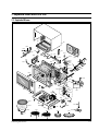
7. Exploded Views and Parts List
7-1 Exploded Views
M2
M3
M1
M58
M4
M59
M57
M13
M5
M14
M7 M8
M9
M56
M15
M10
M16
M29
M47
M51 M22
M55
M17
M18
M11 M12
M23
M69
M54
M19
M20
M53
M28
M30
M27
M24
M52
M21
M62
M26
M51
M61
M50
M25
NC
M33
NO
COM
M34
M46
M31
M35
M36
M35
M37
M60
M32
M38
M45
M44
M63
M39
M48
M41
M42
M65
M67
M72
M40
M49
M64
M43
M68
M73
M70
M71
66
Samsung Electronics
7-1
Exploded Views and Parts List
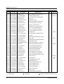
7-2 Main Parts List
Ref. No.
Parts No.
M1
M2
M3
M4
M5
M7
M8
M9
M10
M11
M12
M13
M14
M15
M16
M17
M18
M19
M20
M21
M22
M23
M24
M25
M26
M27
M28
M29
M30
M31
M32
M33
M34
M35
M36
M37
M38
M39
M40
DE70-30029Z
DE63-90035G
DE61-50073D
DE61-70060A
DE61-30185A
DE47-70031B
DE60-40009B
DE63-20017A
DE60-90006A
DE61-50177A
DE61-50115A
DE61-50528A
DE65-20014A
DE39-20058B
DE92-90535A
DE91-40042A
DE61-30129A
DE31-10080A
DE39-40285A
4713-001046
DE65-20031A
DE63-90065E
DE01-00051A
DE66-90013A
DE62-90046A
DE71-60294A
DE61-30132A
3601-000448
DE47-20031A
OM75PH(31)ESS
DE71-60394A
DE93-20019B
DE66-40020A
3405-000178
3405-000175
DE66-90052A
DE66-90053A
DE59-40001A
DE91-70061A
: Option Parts
7-2
Description
PANEL-OUTER
CUSHION-RUBBER
BRACKET-UPPER
SPRING-PLATE
SUPPORTER-HEATER
HEATER-GRILL
WASHER-TEFLON
GASKET-HEATER
FLANGE-RING
BRACKET-EARTH
BRACKET-HEATER
BRACKET-AIR GUIDE
CABLE CLAMP
ASSY POWER CORD
ASSY-COVER BACK
ASSY NOISE FILTER
SUPPORTER-PCB
MOTOR-FAN
WIRE HARNESS-A
LAMP-INCANDESCENT
BUSHING
CUSHION-LAMP
FILM-LAMP
LEVER-DOOR
ADIABATIC-RIGHT
COVER-ADIABATIC
SUPPORTER-MGT
FUSE-FERRULE
THERMOSTAT
ASSY-MAGNETRON
COVER-AIR
ASSY BODY LATCH
LATCH-BODY
SWITCH-MICRO
SWITCH-MICRO
LEVER-SWITCH(A)
LEVER-SWITCH(B)
DIODE-H.V
ASSY-H.V.FUSE
Specification
SECC,T0.6,W405.5,L1174.8,SC-WH
DFA20,T2,W190,L100,BLK
ALSTAR,T0.6,W273,L432,MB6544W
SK-5,T0.5
ALUMINA,T12,NTR
D6.8,230V,1400W,37.0OHM,RE-130
SLOT,ID22.2,OD28,T1.2,TEFLON
BRASS,T1.5,OD30.5,ID22.5
C3604BD,ID22.1,OD26,L4.7,MBGF4
BSS2-A,T1.0,W28,L38,M9GF45
BSS2-A,T1.0,W55,L55.5,M9GF45
ALCOAT,T0.8,W19,L190.5,CE115K
DA-6N,NY-66
KKP-4819D/B232,1.5MM,250V16A,L
RE-1300
DNA-1019C,250V,10A,CMO-CERAMIC
DASS-T9N
AMM92-002AUEE,230V0.20A,MIN255
230V50HZ,RE-1300
240V,104mA,25W,ORG,-,-,25x62mm
DASB-16N,17.8X6.3,NYLON,NTR,SH
PUT-FOAM,T40,W10,L90,M6245
T0.25,W105,L85,CLEAR,RE-1300
POM(F20-01),NTR,MW5630T
T3,W219.3,L214.8,RE-1300
SECC,T0.6,W249.7,L353.5,RE-130
SECC,T0.6,W38,L342.5,MW6630T
250V,10A,SB,CERAMIC,6.35X31.8MM
PW-2N,140/130
OM75PH(31)ESS
NYLON#66,95G,CE115K,BLK
M8145G,NEW,LATCH
POM,50G,M8135G,NEW LATCH
250V,15A,200gf,SPST-NO
250V,15A,200gf,SPST-NO
POM,10G,NTR,MX245
POM,12G,NTR,MX245
HVR-1X-32B-12
THV060T-0800-H,5KV/0.8A,WHT
: Warning
Q'ty
1
1
1
1
1
1
1
1
1
1
1
1
1
1
1
1
2
1
1
1
1
1
1
1
1
1
1
1
1
1
1
1
1
2
1
1
1
1
1
Remarks
PN-OUT
P-CORD
C-PCB
CA-BAK
MGTCO
:Electrostatically Sensitive Devices
Samsung Electronics
Exploded Views and Parts List
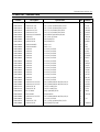
7-2 Main Parts List
Ref. No.
Parts No.
M41
M42
M43
M44
M45
M46
M47
M48
M49
M50
M51
M51
M52
M53
M54
M55
M56
M57
M58
M59
M60
M61
M62
M63
M64
M65
M66
M67
M68
M69
M70
M71
M72
M73
DE26-20084A
DE61-40026A
DE60-60025A
DE61-50106A
2501-001107
DE26-10042B
3601-001126
DE80-10115A
DE65-20025A
DE31-10097A
DE47-20050A
DE47-20050A
DE71-60313A
DE61-80006B
DE61-80037C
DE32-10013A
DE72-60035Q
DE39-40339A
DE39-40409A
DE39-30063A
DE63-90062A
DE74-20025C
DE74-20016A
DE92-90189C
DE67-60028A
DE92-90019P
DE92-90019Q
DE65-20012A
DE74-20022A
DE74-20107A
DE92-90345A
DE92-90334A
Samsung Electronics
Description
TRANS-L.V
FOOT
PIN-FOOT
BRACKET-HVC
C-OIL
TRANS-H.V
FUSE-FERRULE
BASE-PLATE
CABLE CLAMP
MOTOR-SYNCHRONOUS
THERMOSTAT
THERMOSTAT
COVER-CEILING
HINGE-LOWER
HINGE-UPPER
SENSOR-THERMISTOR
GUIDE-AIR
WIRE HARNESS-C
WIRE HARNESS-E
WIRE LEAD-G
ASSY CONTROL-BOX
ASSY DOOR
CUSHION-RUBBER DOOR
TRAY-CONVECTION
TRAY-COOKING
ASSY-GUIDE ROLLER
COUPLER
ASSY-WIRE RACK
ASSY-WIRE RACK
CORD CLAMP
TRAY-OIL
TRAY-BROILER
ASSY-SHAFT BARBECUE
ASSY-LEG
Specification
RE-1280STC,230V,50HZ,AC16/3V,R
PP-JI350,BLK
PP-JI350,BLK
SECC,T0.8,W31,L125.8
1.1uF,2.1KV,BK,54x35x85,20mm
Y9245NTC-1,230V,50HZ,AC2230V,M
250V,1.6A,FA,CERAMIC,5X20MM
SGCC1-Z,T0.8,W544,L345.5,CE115
DAWS-2NB,NYLON66,NTR,WIRE,SADD
M2LJ24ZS52,220/240V,50/60HZ,M6
PW-2N,130/60
PW-2N,130/60
MICA,SHEET,T0.5,W48.5,L117,REZP2W,T3.0,ZN(PLATING),RE-552
SCP1,T3.0,W26,L76,ZP2C-W,MB245
PT-312-K2
SECC,(T)0.6,(W)240,(L)242.5,RE
230V50HZ,RE-1300
230V50HZ,M9G45,CTW
L80,PCB,GROUND
RUBBER(CR),T9,W30,L50,RE-1300
SPP,T0.8,W12,L325.9,CE104CF
GLASS,T5.0,PI345,1250G,M551T
D22.5,RE-1300
PTFE,23G,WHT,RE-1300
CE1279KSE,HIGH
LOW,TRAY-BROIL ONLY
DALC-2-1,SILICON
GLASS(NEOREX),T5,PI210,600G
AL,T0.8,345,345,PI345,ENAMEL,S
M9GF45,STS304,D6,M9GF45
M9GF45
Q'ty
1
4
4
1
1
1
1
1
1
1
1
1
1
1
1
1
1
1
1
1
1
1
1
1
1
1
1
1
1
1
1
1
1
1
Remarks
CV-TCO
GR-TCO
TEMP-W
7-3
Exploded Views and Parts List
7-3 Exploded View & Parts List - Door Parts
D4
D5
D7
D3
D6
D8
D2
D9
D1
Ref. No.
Parts No.
Description
D1
D2
D3
D4
D5
D6
D7
D8
D9
DE64-40064B
DE67-20117B
DE92-50080E
DE64-40173A
DE64-40087H
DE61-70030A
DE60-60008A
DE02-00082A
DE92-40094C
DOOR-A
SCREEN-DOOR(B)
ASSY DOOR-E
DOOR-C
DOOR-KEY
SPRING-KEY
PIN-HINGE
TAPE-DOUBLE FACE
ASSY DOOR
7-4
Specification
PC,RP-WH-01-K,290G,RE-1300
TEMP,GLASS,T3.2XW278XL423.7,VI
MBG45,COATING,SIL/SELANT
PBT,BLK,24G,RE-1300
POM(TC3005),BLK,13G,W3
ES,HSW3,PI0.7,D7.0,L40,BULING,
PI4,L17,MSWR10,M301TBC
PET,T0.4,W9,WHT,SEIL,SI-500HI
CE104CF,WHT,VITALITY
Q'ty
Remarks
1
1
1
1
1
1
2
1
1
Samsung Electronics
Exploded Views and Parts List
7-4 Exploded View & Parts List - Control Parts
C7
C3
C4
C2
C1
C6
C5
C8
Ref. No.
Parts No.
Description
C1
C2
C3
C4
C5
C6
C7
C8
DE34-00033A
DE67-40094A
DE72-70076B
RC-1300-00
DE66-20053B
DE61-70026A
DE93-30482A
DE93-30575B
SWITCH-MEMBRANE
WINDOW-DISPLAY
CONTROL-PANEL
ASSY PCB PARTS
BUTTON-PUSH
SPRING-BUTTON
ASSY CONTROL-PANEL
ASSY CONTROL-BOX
Samsung Electronics
Specification
CE305CF/HAC(CE104CF),120V
ACRYL(HI-855M),RC-SM-04-K,13G,
PC,RP-WH-01-K,180G,RE-1300
RE-1300,AC230V50HZ
PC,RP-WH-01-K,32G,RE-1300
CS,SWP,PI0.7,D17,L25.8
WHT
CE305CF/HAC(CE104CF),WHT
Q'ty
Remarks
1
1
1
1
1
1
1
1
7-5
Exploded Views and Parts List
7-5 Exploded View & Parts List - Casing Parts
A8
A5
A6
A7
A4
A2
A9
A3
A1
A10
Ref. No.
Parts No.
A1
A2
A3
A4
A5
DE60-30016B
DE31-30011A
DE72-30016A
DE62-90045A
DE61-50324A
NUT-FLANGE
FAN-CONVECTION
BUSH-MOTOR
ADIABATIC-CASING
BRACKET-CASING
M4,MSWR10,FEFN
ALSTAR,T0.6,PI109,RE-1300
MSWR3,D5.6,L11.2,RE-1300,ZPC3
T5,W256,L250,RE-1300
ALSTAR,T0.6,W265,L265,RE-1300
1
1
1
1
1
A6
A7
A8
A9
A10
DE31-90019A
DE60-40026A
DE31-10081A
DE65-20012A
DE92-90078A
BLADE-FAN
WASHER-PLAIN
MOTOR-CONVECTION
CORD CLAMP
ASSY-CASING
SECC,T0.6
ID5.5,OD12,T1.0,SBC1
AMM90-003AUEA,230V0.3A,MIN2800
DALC-2-1,SILICON
RE-1300,230V,EUROPE
1
1
1
1
1
7-6
Description
Specification
Q'ty
Remarks
Samsung Electronics
Exploded Views and Parts List
7-6 Parts List - Standard Parts
Parts No.
DE60-10012A
DE60-10012A
DE60-10012A
DE60-10013A
DE60-10013A
DE60-10018A
DE60-10034A
DE60-10046A
DE60-10052A
DE60-10080A
DE60-10080A
DE60-10082H
DE60-10082H
DE60-10082H
DE60-10082H
DE60-10082H
DE60-10082H
DE60-10082H
DE60-10082H
DE60-10082H
DE60-10082H
DE60-10082H
DE60-10082H
DE60-10082H
DE60-10082H
DE60-10098A
DE60-10098A
DE60-10122A
DE60-10122A
DE60-20014A
DE60-30016A
DE60-10098A
DE60-10082H
DE60-10012A
DE60-10088A
Description
SCREW-TAP TITE
SCREW-TAP TITE
SCREW-TAP TITE
SCREW-ASSY TAP
SCREW-ASSY TAP
SCREW-ASSY MACHINE
SCREW-TH
SCREW-TAP PH
SCREW-TAP PH
SCREW-WASHER
SCREW-WASHER
SCREW-A
SCREW-A
SCREW-A
SCREW-A
SCREW-A
SCREW-A
SCREW-A
SCREW-A
SCREW-A
SCREW-A
SCREW-A
SCREW-A
SCREW-A
SCREW-A
SCREW-ASSY TAP TITE
SCREW-ASSY TAP TITE
SCREW-TAP TH
SCREW-TAP TH
BOLT-FLANGE
NUT-FLANGE
SCREW-ASSY TAP TITE
SCREW-A
SCREW-TAP TITE
SCREW-TAP PH
Samsung Electronics
Specification
TH,+,3,M4,L10,SWR10,ZPC2,TOOTH
TH,+,3,M4,L10,SWR10,ZPC2,TOOTH
TH,+,3,M4,L10,SWR10,ZPC2,TOOTH
TH,2S,4,L12,MSWR3,ZPC3,FIBER
TH,2S,4,L12,MSWR3,ZPC3,FIBER
PH,M4X0.7P,8,MSWR10,SN1,WS
TH,+,M4,L10,STS304
PH,M3,L8,FEFZY
PH,M4,L8,FEFZY
M5,L12,2S
M5,L12,2S
2S-4X12,TOOTHED
2S-4X12,TOOTHED
2S-4X12,TOOTHED
2S-4X12,TOOTHED
2S-4X12,TOOTHED
2S-4X12,TOOTHED
2S-4X12,TOOTHED
2S-4X12,TOOTHED
2S-4X12,TOOTHED
2S-4X12,TOOTHED
2S-4X12,TOOTHED
2S-4X12,TOOTHED
2S-4X12,TOOTHED
2S-4X12,TOOTHED
PH,TC,M4X8,SWRCH18A,ZPC2,GLD,W
PH,TC,M4X8,SWRCH18A,ZPC2,GLD,W
TAP,TH,2-4X8,FE,FN
TAP,TH,2-4X8,FE,FN
M5,L10,MSWR3,FEFZY
M4,MSWR10
PH,TC,M4X8,SWRCH18A,ZPC2,GLD,W
2S-4X12,TOOTHED
TH,+,3,M4,L10,SWR10,ZPC2,TOOTH
PH,M3,L8,FEFZY,PLAIN
Q'ty
Remarks
1
1
1
1
4
2
1
2
1
4
4
4
1
2
1
9
1
2
1
2
3
2
2
3
1
2
2
2
2
4
1
4
2
1
5
CH-PCB
P-C-EA
PCB-EA
CB-CMP
CV-MOT
B/EART
SENSOR
MGTCO
B/HING
HVT
MGT
A/CSIG
B/AI-G
B/LATH
B/WAVE
BASE-P
BKT/U
CN-BOX
CV-AIR
CV-BAK
CV/ADI
GR-TCO
GU-AIR
PN-OUT
SU/MGT
CV-TCO
M/DRIV
B/HEAT
C-CEIL
HINGE
SENSOR
LVT
CON-BOX
7-7
8. P.C.B Diagrams
8-1 P.C.B Diagrams
8-1
Samsung Electronics
P.C.B Diagrams
8-2 P.C.B Parts List
No.
Parts No.
P1
P2
P3
P4
P5
P6
P7
P8
P9
P10
P11
P12
P12
P12
P13
P13
P14
P15
P16
P17
P18
P19
P20
P20
P21
P22
P23
P24
P25
P26
P26
P27
P28
P29
P30
P31
P32
P32
P33
P34
P35
P36
P37
P39
P39
P40
P41
P42
P43
P43
P43
P43
3501-000265
3501-000265
3708-000527
3711-000315
3711-002662
DE07-10052A
DE09-30190A
DE13-20016A
DE13-20017A
DE30-20016A
DE61-90048D
0401-001002
0401-001002
0401-001002
0402-001103
0402-001103
0403-000150
0403-000525
0501-000283
0501-000388
0502-000303
0504-001045
2001-000042
2001-000042
2001-000062
2001-000065
2001-000084
2001-000432
2001-000575
2001-000611
2001-000611
2004-000193
2004-001118
2011-001072
2201-000442
2202-000127
2202-000780
2202-000780
2401-000180
2401-000244
2401-000598
2401-000914
2401-001415
2802-000161
3501-000334
3711-000940
3711-000999
DE13-20009A
DE39-60001A
DE39-60001A
DE39-60001A
DE39-60001A
Samsung Electronics
Description
RELAY-POWER
RELAY-POWER
CONNECTOR-FPC/FC/PIC
CONNECTOR-HEADER
CONNECTOR-HEADER
V.F.DISPLAY
IC-MCU
IC-VOLT REGU
IC-DRIVE
BUZZER
HOLDER-DIGITRON
DIODE-SWITCHING
DIODE-SWITCHING
DIODE-SWITCHING
DIODE-RECTIFIER
DIODE-RECTIFIER
DIODE-ZENER
DIODE-ZENER
TR-SMALL SIGNAL
TR-SMALL SIGNAL
TR-POWER
TR-DIGITAL
R-CARBON
R-CARBON
R-CARBON
R-CARBON
R-CARBON
R-CARBON
R-CARBON
R-CARBON
R-CARBON
R-METAL
R-METAL
R-NETWORK
C-CERAMIC,DISC
C-CERAMIC,MLC-AXIAL
C-CERAMIC,MLC-AXIAL
C-CERAMIC,MLC-AXIAL
C-AL
C-AL
C-AL
C-AL
C-AL
RESONATOR-CERAMIC
RELAY-REED
CONNECTOR-HEADER
CONNECTOR-HEADER
IC
WIRE-SO COPPER
WIRE-SO COPPER
WIRE-SO COPPER
WIRE-SO COPPER
Specification
Q'ty
12V,-,16A,-,15mS,15mS
12V,-,16A,-,15mS,15mS
12P,2.54mm,STRAIGHT,SN
1WALL,7P,1R,3.96mm,STRAIGHT,SN
BOX,2P,1R,2.5mm,STRAIGHT,SN
SVM-4MS13S,MWO,RE-1280
TMP47C862H-P582CZ,DIP,RE-1300,
KA7805A,TO-220AB,1A,0/125C
KID65003AP,DIP,16P,STICK,TR-AR
CBE2220BA,STICK
NYLON#66,10G,BLK
1N4148M,100V,200mA,DO-34,TP
1N4148M,100V,200mA,DO-34,TP
1N4148M,100V,200mA,DO-34,TP
1T4,400V,1A,TS-1,TP
1T4,400V,1A,TS-1,TP
1N4743A,13V,5%,1W,DO-41,TP
1N4733A,5.1V,5%,1W,DO-41,TP
KSA539,PNP,400mW,TO-92,TP,120KSC815,NPN,400mW,TO-92,BK,120KSD882,NPN,1W,TO-126,TP,160-32
KRC119M,NPN,400MW,4.7K/10K,TO-92
1KOHM,5%,1/4W,AA,TP,2.4X6.4MM
1KOHM,5%,1/4W,AA,TP,2.4X6.4MM
470OHM,5%,1/4W,AA,TP,2.4X6.4MM
10KOHM,5%,1/4W,AA,TP,2.4X6.4MM
100KOHM,5%,1/4W,AA,TP,2.4X6.4MM
1MOHM,5%,1/4W,AA,TP,2.4X6.4MM
2KOHM,5%,1/4W,AA,TP,2.4X6.4MM
3.9KOHM,5%,1/4W,AA,TP,2.4X6.4MM
3.9KOHM,5%,1/4W,AA,TP,2.4X6.4MM
100Kohm,1%,1/4W,AA,TP,2.4x6.4m
5Kohm,1%,1/4W,AA,TP,2.4x6.4mm
47KOHM,5%,1/8W,A,SIP,6P,TP
3.3nF,10%,50V,X7R,-,-,08x5.0
10nF,+80-20%,25V,Y5V,TP,-,7.5
100nF,+80-20%,50V,Y5V,TP,3.5x1
100nF,+80-20%,50V,Y5V,TP,3.5x1
1000uF,20%,35V,GP,-,16x25x7.5m
100uF,20%,10V,GP,TP,6.3x7,5
1uF,20%,50V,GP,TP,4x7,5
22uF,20%,16V,GP,TP,5x11,5
470uF,20%,35V,GP,TP,10x20,5
4MHz,0.5%,TP,10.0x5.0x7.5mm
12V,1250VA,10A,-,10mS,5mS
BOX,4P,1R,2.5mm,STRAIGHT,SN
BOX,5P,1R,2.5mm,STRAIGHT,SN
KA7533,DIP,-,-,-,-,PI0.6,SN,T,52MM,TAPING_WIRE
PI0.6,SN,T,52MM,TAPING_WIRE
PI0.6,SN,T,52MM,TAPING_WIRE
PI0.6,SN,T,52MM,TAPING_WIRE
2
2
1
1
1
1
1
1
1
1
1
5
5
4
5
3
1
2
1
2
1
2
5
1
3
5
1
1
1
5
6
1
1
1
5
1
5
3
1
1
2
1
2
1
1
1
1
1
6
6
6
5
Remarks
GRILL, INRUSH
MAIN, POWER
CON03
CON04
CON05
V-REG
IC02
BUZZER
D07,D08,D09,D12,D13
D14,D15,D16,D17,D18
D19,D20,D21,D22
D01,D02,D03,D04,D05
D06,D10,D11
ZD02
ZD01,ZD03
Q03
Q04,Q05
Q01
Q02,Q06
R04,R10,R19,R27,R28
R30
R01,R02,R03
R06,R09,R11,R12,R17
R14
R07
R18
R05,R08,R13,R15,R16
R20,R23,R24,R25,R26,R29
R22
R21
AR04
C14,C15,C16,C17
C09
C06,C07,C08,C11,C13
C18,C19,C20
C01
C04
C10,C12
C05
C02,C03
X-TAL
CONV., FAN
CON02
CON01
RESET
J01,J02,J03,J04,J05,J06
J07,J08,J09,J10,J11,J12
J13,J14,J15,J16,J17,J18
J19,J20,J21,J22,J23
8-2
9. Schematic Diagrams
9-1 Schematic Diagrams
S/W1
S/W2
V/G
E
H
F
WHT
BLU
RY1
2200pF
ROT
RY4
BRN
H.V.T
YEL
RY5
CM
FM
DM
F2
(0.8A)
YEL
BLK
YEL
WHT
R
BLU
YEL
WHT
F3
(1.6A)
RY6
YEL
RY2
BLU
H.V.D
H.V.C
S/W5
ORG
BLU
0V
ORG
WHT
L
ORG
ORG
E
N
BLU
BRN
WHT
WHT
1mH
500K
WHT
2200pF
230V~
50Hz
S/W3
BRN
BRN
F1
S/W6
BRN
LIN-CAPACITORT 0.1uF
L
BRN
FUSE 10A
BRN
L.V.T
Ass'y chike P.C.B
ORG
F
BLU
BLU
FA
RY3
MAGNETRON
RY2
RY3
RY4
RY5
S/W4
RY6
ORG
KEY BOARD
OFFENZUSTAND
GRN
ORG
RY1
DOOR IS OPENED
COOK OFF
A S S Y M A I N P.C.B
WIRING COLOR
BRN :BROWN BLU : BLUE
WHT : WHITE ORG : ORANGE
RED : RED
YEL : YELLOW
Y/G : YELLOW/GREEN
COM NO
BRN
COM NO
BRN WHT
PRIMARY LATCH
SWITCH
ORG
ORG
DOOR SENSING
SWITCH
NO
COM NO
BRN YEL
RED BLU
BRN
MONITOR
SWITCH
F1
F2
F3
S/W1
S/W2
S/W3
S/W4
S/W5
S/W6
RY1
RY2
RY3
RY4
RY5
RY6
MAIN FUSE
H.V.FUSE
MONITOR FUSE
THERMAL CUTOUT(CAVITY)
THERMAL CUTOUT(M.G.T)
PRIMARY SWITCH
DOOR SENSING SWITCH
MONITOR SWITCH
THERMAL CUTOUT(HEATER)
HEATER RELAY
MAIN RELAY
POWER RELAY
CONVECTION MOTOR RELAY
FAN MOTOR RELAY
INRUSH RELAY
FM
DM
CM
H
H.V.T
H.V.C
H.V.D
L.V.T
L
R
FAN MOTOR
DRIVE MOTOR
CONVECTION MOTOR
HEATER
HIGH VOLTAGE TRANS
HIGH VOLTAGE CAAPCITOR
HIGH VOLTAGE DIODE
LOW VOLTAGE TRANS
LAMP
RESISTOR
MAGNETRON
HIGH VOLTAGE
DIODE
TO CHASSIS
FA
F
HIGH VOLTAGE CAPACITOR
ORG
RED
RED
H.V.FUSE
BRN
RED
BLU
SYMBOL COLOR
ORG
ORANGE
BRN
BROWN
BLK
BLACK
RED
RED
BLU
BLUE
HIGH VOLTAGE
TRANSFORMER
9-1
Samsung Electronics