1
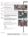
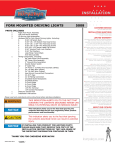
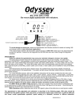
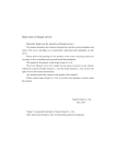
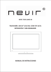
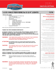
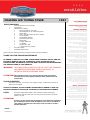
INSTALLATION
CHASING LED TIMING COVER
1302
PARTS INCLUDED
1
1
1
1
1
Chasing LED Point Cover Assembly
Finned Cone
Hardware Kit including;
1
Mounting Plate for Twin Cam
1
Mounting Plate for XL and Evo Big Twins
1
Spacer Ring
5
8-32 x 3/8 Flat Socket Cap Screw (FSCS)
1
10-24 Hex Nut
2
#10 SAE flat washers
1
Dielectric Grease Pack
1
Alcohol Pad
4
4” Nylon cable Ties
1
“Y” Adapter
1
Scotch Lock, male
1
T-Tap Scotch Lock, female
Controller Switch
Installation Instructions
Please read and understand entire instructions before starting installation.
THANK YOU FOR CHOOSING KϋRYAKYN!
IN ORDER TO PROTECT YOU AND OTHERS FROM POSSIBLE INJURY AND/OR
PROPERTY DAMAGE OR LOSS, PLEASE PAY CLOSE ATTENTION TO ALL
INSTRUCTIONS, WARNINGS, CAUTIONS AND ATTENTION NOTES REGARDING
THE USE AND CARE OF THIS PRODUCT.
WARNING!
THIS INDICATION ALERTS YOU TO THE FACT THAT IGNORING
THE CONTENTS DESCRIBED HEREIN CAN RESULT IN
POTENTIAL DEATH OR SERIOUS INJURY
ATTENTION! This indication alerts you to the fact that ignoring the contents
described herein may negatively affect product performance and
functionality.
TOOLS SUGGESTED
Set of hex wrenches, Torx drivers, wire stripper/crimper, combination wrenches or
socket set and ratchet.
STRICTLY OBSERVE THE FOLLOWING GUIDELINES IN ORDER TO USE THE
PRODUCT PROPERLY AND AVOID POTENTIALLY DANGEROUS ACCIDENTS.
STEP 1
Read and understand all steps in the instructions before starting the
installation. Park the motorcycle on a hard, level surface and turn off the
ignition. Let cool.
ATTENTION!
A factory service manual may be helpful in performing this installation.
Do not attempt to perform this installation if you are not confident in
your ability to complete all of the steps in the procedure; consult a
trained technician.
-cont.1302-24HD-0111
CUSTOMER SERVICE
877.370.3604 (toll free)
INSTALLATION QUESTIONS
[email protected]
or call 715.247.2983
LIMITED WARRANTY
Küryakyn warrants that any Küryakyn products
sold hereunder, shall be free of defects in
materials and workmanship for a period of one
(1) year from the date of purchase by the
consumer excepting the following provisions:
● Küryakyn shall have no obligation in the event
the customer is unable to provide a receipt
showing the date the customer purchased the
product(s).
●The product must be properly installed,
maintained and operated under
normal conditions.
●Küryakyn makes no warranty, expressed or
implied, with respect to any gold plated
products.
●Küryakyn shall not be liable for any
consequential and incidental damages, including
labor and paint, resulting from failure of a
Küryakyn product, failure to deliver, delay in
delivery, delivery in nonconforming condition, or
for any breech of contract or duty between
Küryakyn and a customer.
●Küryakyn products are often intended for use in
specific applications. Küryakyn makes no
warranty if a Küryakyn product is used in
applications other than intended.
●Küryakyn electrical products are warranted for
one (1) year from the date of purchase by the
consumer. L.E.D.’S contained in components of
Küryakyn products will be warranted for defects
in materials and workmanship for 3 years from
the date of purchase where as all other
components shall be warranted for one(1) year.
This includes, but is not limited to; control
modules, wiring, chrome & other components.
●Küryakyn makes no warranty of any kind in
regard to other manufacturer¹s products
distributed by Küryakyn. Küryakyn will pass on
all warranties made by the manufacturer and
where possible, will expedite the claim on behalf
of the customer, but ultimately, responsibility for
disposition of the warranty claim lies
with the manufacturer.
ABOUT OUR CATALOG
For purchasing Küryakyn® products, you
can receive a complete catalog free of charge.
Send the Proof-of-Purchase below with
your address to: Küryakyn, P.O. Box 339,
Somerset, WI 54025.
Please indicate either Accessories Catalog for
Harley-Davidson® or GL & Metric Cruisers.
Be sure to ask your local dealer about other
Küryakyn® products, the motorcycle parts and
accessories designed for riders by riders.
©2005 Küryakyn USA® All Rights reserved.
WARNING!
YOU WILL BE WORKING AROUND THE ENGINE AND EXHAUST SYSTEM
DURING INSTALLATION. ENSURE THAT THE ENGINE AND EXHAUST SYSTEM
HAVE FULLY COOLED TO PREVENT INJURY.
STEP 2
Remove the fasteners which secure the timing cover, the fasteners and cover
will no longer be used.
BEVELED PLATE AND BEAUTY
RING FOR EVO AND SPORTSTERS
PIC 1
Note: The flat plate with five holes is for twin cam motors. The beveled plate and
the spacer ring are for Evo and XL motors. PIC. 1
STEP 3
Install the appropriate plate, using the 8-32 x 3/8 FSCS screws from the
hardware kit (five if mounting on a Twin Cam or two if mounting on an XL or
Evo). PIC. 2.
STEP 4
Place the LED cover over the stud on the mounting plate; be sure to route the
wires away from the exhaust, engine or any moving parts.
FLAT PLATE FOR
TWIN CAM
Note: When installing on Evo or XL motors, place the spacer ring against the
mounting plate so that it is behind the cover, making sure that the timing
cover wiring is placed in the “notch” of the spacer ring.
STEP 5
Secure the cover using the 10-24 Hex Nut and #10 flat washer. PIC. 3.
STEP 6
Install the finned cone, tightening until it clicks several times.
PIC 2
Wiring
STEP 1
Remove the seat and the side panel (on touring models).
STEP 2
Determine a location on you bike to mount the control switch. This location
needs to be close enough to the chasing LED cover so that the wiring harness
from the cover will reach the wiring harness from the switch; and the power
wires will reach the battery terminals.
STEP 3
The black wire from the switch is a ground wire and needs to be secured to the
negative terminal on the battery.
STEP 4
The red wire from the switch (with in-line fuse) is a power wire and needs to be
secured to the positive terminal on the battery.
STEP 5
Locate the ignition harness (carbureted), or the electronic fuel injection harness
which is most commonly located under the seat or under the side cover on the
right hand side of the motorcycle. PIC. 4 and PIC. 5.
STEP 6
Carefully expose the wires located inside the harness cover.
STEP 7
Locate the front (blue with orange trace) or rear (yellow with blue trace) coil
wire inside the harness on all models other than 2011 Softails. On 2011
Softail models, the front coil
wire is green with a blue
PIC 5
tracer and the rear coil wire
is gray with a blue tracer.
PIC 8
WIRE HARNESS
TWIN CAM MOUNTING SHOWN
PIC 3
10-24 HEX NUT
AND WASHER
ROUTE WIRE AWAY
FROM EXHAUST
PIC 4
UNDER SEAT
Note: Refer to an H-D electrical
WIRE HARNESS
BEHIND SIDE
PANEL
diagnostic manual to
verify the correct wire
colors for your
motorcycle.
PAGE
2
-cont.-
CHASING LED TIMING COVER
INSTALLATION
STEP 8
Place the T-Tap connector over the front or rear coil wire and close ensuring that the tab is
engaged. PIC.6, 7 & 8
ATTENTION! Küryakyn recommends the use of dielectric grease on electrical connections.
STEP 9
Insert the purple wire from the control switch into
the male Scotch Lock and crimp, making sure that
the wire is secure.
PIC 6
NOTE: Picture 8 is for 2011 Softails only. Picture 7 is
for all other years and models.
FEMALE T-TAP
STEP 10
Now, hook the purple wire with the male Scotch
Lock from the control switch, to the T-Tap that was
installed on the coil wire. PIC 7 or PIC 8
STEP 11
Plug the wiring harness from the chasing LED cover into the harness from the switch.
NOTE: Use the included Y Adapter harness if using multiple seven color chasing
products on your motorcycle. One controller is capable of handling up to
four units.
STEP 12
MALE SPADE
PIC 7
BLUE WIRE WITH
ORANGE TRACER
Secure all wiring away from heat sources and or moving parts using the
included cable ties. Melted wire insulation may result in a short circuit.
ATTENTION! Secure all wiring away from any moving parts, pinch points or
extreme heat. Küryakyn WILL NOT warranty any electrical
component that fails due to pinched, crimped, broken, abraded,
melted or frayed wires.
STEP 13
Reinstall the seat and the side panel.
ATTENTION! It is the installer’s responsibility to ensure that all of the
fasteners (including pre-assembled) are tightened before operation of the motorcycle.
Küryakyn will not warranty components lost due to improper
installation. Periodic maintenance may be required.
PIC 8
2011 SOFTAILS
ONLY
Controller Switch Operation
• Flip the switch to the “mode” position and press the selector button to
choose either the “chasing mode” or the “steady illumination mode.”
• Flip the switch back to the “color” position, and press the selector button to
choose the color; the color sequence is as follows:
1. Red
2. Lime
3. Ice White
4. Sky Blue
5. Dark Blue
6. Purple (Violet)
7. Green
8. Paint Mode (continuously cycles through all seven colors)
GRAY WIRE WITH
BLUE TRACER
• Flip the switch back to the “mode” position.
PAGE
3
Ride On!
CHASING LED TIMING COVER
INSTALLATION