1
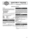
Oil Filter Cooler installation instructions
PART #
#2000
#2001
#2002
#2003
#2005
#2006
#2007
#2008
FINISH
CHROME
CHROME
CHROME
CHROME
BLACK CHROME
BLACK CHROME
BLACK CHROME
BLACK CHROME
MODEL
‘99 – ‘10 SOFTAIL MODELS
‘99 – ‘10 DYNA MODELS
‘99 – ‘10 BAGGER MODELS, FL, FLHT, FLHR, FLTR
‘99 – ‘10 DYNA MODELS W/O CHARCOAL CANISTER
‘99 – ‘10 SOFTAIL MODELS
‘99 – ’10 DYNA MODELS
‘99 – ’10 BAGGER MODELS, FL, FLHT, FLHR, FLTR
‘99 – ‘10 DYNA MODELS W/O CHARCOAL CANISTER
#2020
REPLACEMENT OIL FILTER #’S: 2000, 2001, 2002, 2003, 2005, 2006, 2007, 2008
IMPORTANT NOTICE
This installation should be done by an experienced mechanic who has access to a factory service manual and all required
tools.
CAUTION
Incorrect installation can cause engine damage not covered under warranty. Failure to install components correctly can cause
engine seizure. Engine seizure may result in serious injury to motorcycle, operator, passenger, and/or others.
CAUTION
Read instructions in their entirety before attempting installation. Failure to follow instructions may result with engine oil
starvation, oil leaks, and product failure. Always re-torque fasteners after first heat cycle and at every oil change.
IMPORTANT NOTICE
*Check clearances from filter housing to rear of front fender, the filter housing must clear when front end is fully
compressed. Some Softail models may require extra clearance. Minor bracket modification may be needed to clear
the front fender and or voltage regulator.
*The use of a high volume oil pump will result in cleaner cooler oil because of the increased volume through the filter
cooler
1. See Figure 1 to verify all Feuling components and the proper mounting bracket for your model
2. Wash, clean and inspect all new Feuling hardware, Including - off-set sandwich oil filter adapter, filter
cooler housing and oil lines, use compressed air to blow dry the oil lines, fittings, threads and bolt holes.
Use a tap and die if needed to clean threads. (On installation use lubrication on all fasteners and fittings)
3. Refer to the proper service manual for your model motorcycle & engine, for removal of engine oil and
spin-on oil filter. Dispose of these items properly.
4. Clean engine case oil filter spigot and sealing surface thoroughly.
5. Install the clean Feuling off set oil filter sandwich adapter; both O-ring and gasket need to be assembled
dry.
6. First install the inside half of the off-set oil filter adapter, O-ring side towards engine case filter mount.
We recommend using a dab loctite on the 1” lock nut. (See figure 2) It is recommend to mock up the
sandwich adapter before torquing nuts and bolts to obtain desired orientation and proper clearance to
engine case and frame rails.
7. Install the fittings and oil lines onto the outer half of sandwich adapter torque fittings to proper specs
using thread sealant on the 1/8 NPT threads and engine oil on the -4 AN oil line fittings.
8. Complete installation of sandwich adapter, including the inner gasket. Finger tight the allen head bolts in
an alternating sequence on both sides before final torque. Re-Torque the allen head bolts after the first heat
cycle after installation and during every oil change.
9. The sandwich oil filter adapter has an IN and an OUT. The fitting on the front side of the motorcycle is
the OUT and the rear fitting is the IN. (See figure 3)
10. The filter cooler has an IN and OUT, the IN end cap has the larger hole and the OUT end cap has a
smaller more restrictive hole. We recommend mounting the filter cooler so the IN is on the right side of
the motorcycle and the OUT is facing to the left. (See figures 5)
11. Soak the new Feuling oil filter element in a tub and fill the new K&N spin on filter with your preferred
engine oil. This process should take approx. 15 – 20 min.
12. Mounting Instructions:
*Check clearance of filter housing to front fender
Softail Models – Mount filter cooler to supplied bracket using supplied washers and lock nuts. Remove
stock ¼” voltage regulator bracket bolts, mount Feuling filter cooler using supplied bolts to voltage regulator
location. We recommend using loctite on the supplied ¼” bolts (See Fig. 7, 8). If more clearance is desired
between the filter housing and frame rails install spacers or washers behind bracket to get desired location.
Minor modification to bracket may be required to clear voltage regulator and or frame rails. Check
clearance between filter housing and front fender with front end fully compressed. Bracket may
need minor modification for filter cooler to clear fender. Some Softail models are equipped with a plastic
wire cover on the top side of the voltage regulator, this plastic cover may need to be removed or modified.
Bagger Models, FL, FLHT, FLHR, FLTR – Mount filter cooler to supplied bracket using supplied washers
and lock nuts. Remove stock nuts on voltage regulator, lift up stock regulator bracket, place Feuling filter
cooler with bracket onto the stock studs, place stock regulator bracket over Feuling bracket and into position
then tighten nuts. We recommend using loctite on the studs & nuts. (See Fig 9, 10)
Dyna Models – Remove bottom front engine mount bolt, place Feuling bracket into position then finger
tighten the bottom bolt to the bracket. Remove top engine mount bolt rotate bracket into position (the
bracket will simulate a T) then finger tighten top bolt. Torque engine mount bolts to factory specs, we
recommend using loctite on bolt threads. Mount filter cooler to bracket using the supplied washers and lock
nuts.
13. Install the oil soaked Feuling filter element into the filter cooler housing, check O-rings and spring for
proper fitment. Apply lube to the 12 point fasteners, threads and underhead flanges, before installing.
14. Install the new K&N spin on filter; use a socket on the filter nut to tighten filter. Apply engine oil to Oring before installing.
15. Install banjo fittings, washers and bolts into filter cooler housing. If the oil line interferes with the
housing end cap use the thicker copper washer - place the thick crush washer on the inside (housing
side). Place the thinner crush washer on the outside (against the head of the banjo bolt). Use lubrication
on all threads and underhead flanges. (See figure 4)
16. Route oil lines from the sandwich oil filter adapter to the filter cooler. Lube fittings with engine oil before
finger tightening. See torque chart for torque specs. Route oil lines to the left frame rail and away from
the exhaust pipes. Use the supplied zip ties with the clear plastic frame protectors to fasten the oil lines
to the frame rail. (See Fig. 11)
17. Oil Line Routing: The OUT of the sandwich adapter (front or left) routes to the IN of the filter cooler
(large hole end cap w/spring). The OUT of the filter cooler (small hole end cap w/ black washer) routes
to the IN of the sandwich adapter (rear or right). (See figures 3, 5, 6)
*Re Torque all fasteners after first heat cycle and at every oil change
TORQUE VALUES w/LUBED threads
-4 AN Aluminum Fittings =
100 – 105 Inch / LBS
-4 AN Steel Fittings = 135 – 190 Inch / LBS
10-24 allen head Bolts 32 - 35 Inch/ LBS
6 mm 12 point bolts
150 – 165 inch/ lbs
5/16”-18 nuts
16 – 18 FT./lbs
*Fitting mating surfaces and threads should be lubricated with your preferred engine oil prior to assembly.
*Avoid over tightening as this can cause deformation to the AN 37 degree fitting seats and or sealing surfaces causing permanent damage.
___________________________________________________________________________________________
(Figure 2)
(Figure 3)
*Oil feeds cooler housing from left side fitting ‘out’
*Oil returns to engine through right side fitting ‘in’
(Figure 4)
If oil line interferes with end cap
use thick crush washer on inside
__________________________________________________________________________________
(Figures 5)
______________________________________________________________________________________________________________________
(Figure 6)
(Softail - Figure 7)
(Softail Figure 8)
Softail line routing
(FL - Figure 9)
(FL - Figure 10)
FL line routing
Dyna Models
*Re-Torque all fasteners and fittings after first heat cycle and at every oil change
PARTS LIST
CHROME
FILTER HOUSING, ASSEMBLY
OFF-SET FILTER ADAPTER, ASSEMBLY
BANJO FITTING QTY. 2
BANJO BOLT QTY. 2
1/8” NPT TO -4AN FITTING QTY. 2
12 POINT ARP BOLT QTY.4
K&N CHROME OIL FILTER
2000-1
2000-2
2000-3
2000-4
2000-5
2000-6
KN-171C
SOFTAIL BRACKET
DYNA BRACKET
BAGGER, FL, FLHT, FLHR, FLTE BRACKET
5/16 BOLTS QTY.2
5/16 FLAT WASHERS QTY. 2
5/16 LOCK NUTS QTY. 2
SOFTAIL 3/8” SPACERS QTY. 2
SOFTAIL 12 PT. 1 ¼ - ¼” BOLTS QTY. 2
COPPER CRUSH WASHER (THICK) QTY. 2
COPPER CRUSH WASHER (THIN) QTY. 2
BLACK PRESS ON WASHER, OUT END CAP
O-RING, FILTER HOUSING END CAP QTY. 2
SANDWICH ADAPTER GASKET
SANDWICH ADAPTER O-RING
BRAIDED LINES, STAINLESS 17” SOFTAIL, FLT
BRAIDED LINES, STAINLESS 26” DYNA
BRAIDED LINES, BLACK 17” SOFTAIL, FLT
BRAIDED LINES, BLACK 26” DYNA
10-24 X .600” QTY. 2
10-24 X 1.00” QTY. 3
REPLACEMENT FILTER COOLER ELEMENT
BLACK
FILTER HOUSING, ASSEMBLY
OFF-SET FILTER ADAPTER, ASSEMBLE
BANJO FITTING QTY. 2
BANJO BOLT QTY. 2
1/8” NPT TO -4AN FITTING QTY. 2
12 POINT ARP BOLT QTY.4
K&N BLACK OIL FILTER
2005-1
2005-2
2005-3
2005-4
2005-5
2005-6
KN-171B
2000-7
2001-7
2002-7
2000-8
2000-9
2000-10
2000-11
2000-12
2000-13
2000-14
2000-15
2000-16
2000-17
2000-18
2000-19
2000-20
2000-21
2000-22
2000-23
2000-24
2020
WARRANTY:
All parts are guaranteed to the original purchaser to be free of manufacturing defects in materials and workmanship for a period of twelve (12) months from the date of purchase. Merchandise that fails
to conform to these conditions will be repaired or replaced at FOP’s option if the parts are returned to FOP by the purchaser within the (12) month warranty period.
In the event warranty service is required, the original purchaser must notify FOP of the problem immediately. Some problems may be rectified by a telephone call and need no further action. A part
that is suspect of being defective must not be replaced without prior authorization from FOP. If it is deemed necessary for FOP to make an evaluation to determine whether the part was defective, it must
be packaged properly to avoid further damage, and be returned prepaid to FOP with a copy of the original invoice of purchase and a detailed letter outlining the nature of the problem, how the part was
used and the circumstances at the time of failure. After an evaluation has been made by FOP and the part was found to be defective, repair, replacement or refund will be granted.
ADDITIONAL WARRANTY PROVISIONS:
FOP shall have no obligation in the event an FOP part is modified by any other person or organization, or if another manufacturer’s part is substituted for one provided by FOP. FOP shall have no
obligation if an FOP part becomes defective in whole or in part as a result of improper installation, improper break-in or maintenance, improper use, abnormal operation, or any other misuse or
mistreatment. FOP shall not be liable for any consequential or incidental damages resulting from the failure of an FOP part, the breach of any warranties, the failure to deliver, delay in delivery, delivery
in non-conforming condition, or any other breach of contract or duty between FOP and the customer.The installation of parts may void or otherwise adversely affect your factory warranty. In addition,
such installation and use may violate certain federal, state and local laws, rules and ordinances as well as other laws when used on motor vehicles operated on public highways, especially in states where
pollution laws may apply. Always check with federal, state, and local laws before modifying your motorcycle. It is the sole and exclusive responsibility of the user to determine the suitability of the
product for his/her use, and the user shall assume all legal, personal injury risk and liability and all other obligations, duties and risks associated therewith. Our high performance parts, engines and
motorcycles are intended for experienced riders only. Feuling Oil Pump Corporation reserves the right to change prices and/or discounts without notice and to bill at the prevailing prices at the time of
shipments. The words Harley®, Harley-Davidson® and H-D® and all H-D® part numbers and model designations are used in reference only. Feuling Oil Pump Corporation is in no way associated
with, or authorized by Harley-Davidson Motor Co®. To manufacture and sell any of the engine parts described in this instruction sheet.
17215 ROPER STREET, MOJAVE CA 93501 PH. 619-917-6222 FAX 760-487-1545 WWW.FEULINGPARTS.COM