1
NEPTUNE 4 FA
Service Manual
Item nr 107146560
Version 02– 22– 2011
Preface
This service manual contains detailed description of the main repair work on the hot HPW
NEPTUNE 4 FA.
Repair work requires a suitable testing workplace with the necessary water and power supply.
If operating errors are evident, refer the customer to the operating instructions.
A fault in the cleaner can have several causes as described in the section on troubleshooting.
Refer to the illustrated spare parts lists during repairs. They show the assembly position and
the sequence in which the individual components should be assembled.
See ”Technical Service Bulletin” (TSB) sheets—
Previously called ”Service Technical Information” (STI). They include information on technical
modifications that have been made after this repair manual was printed.
”Technical Service Bulletin” sheets are also valid as a supplement to the spare parts list until
publication of a new edition.
Repair manuals and ”Technical Service Bulletin” sheets should be available at the site where
repairs are carried out.
It is not permitted to give them to third parties.
Use original Nilfisk-ALTO spare parts only.
NEPTUNE FA_EN_Ver.2.0_ 22/11
2
Index
Safety Instructions ................................................................. 4
Technical Data ........................................................................ 5
Construction ......................................................................... 17
Side view ...................................................................... 17
Top view ....................................................................... 17
Frame and cabinet ........................................................ 18
Operation panel ............................................................ 19
Panel—inside................................................................ 19
Electrical box ................................................................ 19
PCB A1 ......................................................................... 20
Boiler ............................................................................ 21
Motor - Pump unit ......................................................... 22
By-pass valve ............................................................... 22
Flow control .................................................................. 22
Function ................................................................................ 23
Display .......................................................................... 23
Hot water function......................................................... 25
Sensors and actors....................................................... 26
Motor/pump................................................................... 27
Working pressure.......................................................... 28
By-pass pressure.......................................................... 28
Water reduction ............................................................ 29
Flow control .................................................................. 30
Troubleshooting ................................................................... 31
Boiler performance ....................................................... 33
Service / Repair .................................................................... 34
Observations................................................................. 34
Oil maintenance............................................................ 34
Fuel filter ....................................................................... 34
Electrical system - Maintenance ................................... 35
By-pass system ............................................................ 36
Valves ........................................................................... 37
Cylinder block ............................................................... 39
Wobble disc system...................................................... 41
Electrical motor ............................................................. 43
Fuel tank ....................................................................... 44
Heating system ............................................................. 44
Exhaust temperature sensor......................................... 45
Burner unit .................................................................... 45
Heat exchanger ............................................................ 46
Torque specifications.................................................... 47
Adjustment of by-pass system ...................................... 48
Burner settings.............................................................. 50
Electric settings……………………………………………..52
Service time settings..................................................... 52
Wiring diagrams ................................................................... 53
Notes ..................................................................................... 62
NEPTUNE 4 FA_EN_Ver.2.0_ 22/11
3
Safety instructions
For your own safety
A
Observe valid safety regulations
for electrical equipment. In
particular, observe the following
regulations:
IEC 60335-2-79
EN 60335-2-79
Additionally:
Also see national regulations
Repair work should be carried
out by persons instructed in
electrical installations or by
trained electricians only.
ESD measures
(electrostatic discharge)
Before using the cleaner, always
read the operating instructions
and keep them readily available.
Only allow the high pressure
cleaner to be used by persons
who have been trained in its use
and who have been explicitly
authorized to use it.
Take the following ESD precautions before carrying out any
repairs to the electronics:
Touch the earth conductor before repairing the cleaner
( to discharge electrostatic charge from your body ).
Wear wrist band if necassary.
Use a conductive floor covering or a conductive table cover.
Never touch the printed circuit board or electronic components
( always hold on to plastic ).
Transport electronic components in conductive packaging
( e.g. ESD bag ).
NEPTUNE 4 FA_EN_Ver.2.0_ 22/11
4
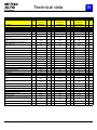
Technical data
B
NEPTUNE 4 FA
Description
Gen.
Tol. 4-39FAX EU 400/3/50/
Item no.
107146600
Technical Data
Test Result
4-43FAX EU
400/3/50/16
4-50FA EU
400/3/50/13
107146601
Tol. + Tol. -
Test Result
107146602
Tol. + Tol. -
Test Result
Tol. + Tol. -
Pump-Data
Max. inlet pressure (bar)
10
10
10
Max. Inlet temperature (°C)
40
40
40
Pressure at pump head
Pressure @ Cylinder Head (bar)
Pressure @ Outlet (bar)
Pressure @ after Gun (bar)
Pressure cut off @ Cylinder Head
(bar)
5,50
%
5,50
%
5,50
%
5,50
%
Pressure Pmax safety valve
Flow. Qiec (l/min)
Flow. Qmax (l/min)
Flow. Qmin, steam (l/min)
2,90
%
5%
3,00
%
Type
152
+8 /
-8
166
+9 /
-9
175
+10 /
-10
158
+9 /
-9
172
+9 /
-9
181
+10 /
-10
140
+8 /
-8
160
+9 /
-9
163
+9 /
-9
126
+7 /
-7
138
+8 /
-8
142
+8 /
-8
178
+5 /
-5
192
+5 /
-5
201
+5 /
-5
250
+5 /
-5
250
+5 /
-5
250
+5 /
-5
11,55
+0,3 / -0,3
12,20
+0,4 / -0,4
13,70
+0,4 / -0,4
12,50
+0,6 / -0,6
13,10
+0,7 / -0,7
14,60
+0,7 / -0,7
6,00
+0,2 / -0,2
6,50
+0,2 / -0,2
7,00
+0,2 / -0,2
NA5
NA5
NA5
Ceramic
Ceramic
Ceramic
20
20
20
Pump oil type
8,7
Oil BP Energol GR-XP
220
9,15
Oil BP Energol GR-XP
220
10,2
Oil BP Energol GR-XP
220
Oil volume (l)
0,95
0,95
0,95
Piston type
Piston diameter (mm)
Stroke / Wobble disc angle
Electronics
Elec. V/Ph/Hz
400V/3~/50Hz
400V/3~/50Hz
400V/3~/50Hz
Current consump. - hot (A)
9,2
+1,0 / -3,0
9,7
+1,0 / -3,0
12,2
+1,0 / -3,0
Current consump. - cold (A)
Power Consumption - hot (kW) hot
10
+1,0 / -3,0
10,5
+1,0 / -3,0
12,5
+1,0 / -3,0
4,7
+0,5 / -0,5
5,2
+0,5 / -0,5
6
+0,5 / -0,5
Fuse size (A)
16
16
16
Cord type
H07RN-F 3G1,5 x 6m
H07RN-F 3G1,5 x 6m
H07RN-F 4G1,5 x 6m
Plug type
CEE7 / 16A Schuko
CEE7 / 16A Schuko
CEE 3P+N+G / 16A
PCB
PCB
PCB
24 Volt-Control voltage
24 Volt-Control voltage
24 Volt-Control voltage
100-C12KJ10 5,5kW
100-C12KJ10 5,5kW
100-C12KJ10 5,5kW
106427170
106427170
106427170
Control
Control voltage
Contactor
Electrical diagram
Eletrical test data
Highvoltage (HV) test (V)
1000 Vac
1000 Vac
1000 Vac
≥ 1MΩ / 500Vdc
≥ 1MΩ / 500Vdc
≥ 1MΩ / 500Vdc
0,20
0,20
0,20
3~ Induction
3~ Induction
3~ Induction
1450
1450
1450
Class F
Class F
Class F
Protection Class
IP54
IP54
IP54
Nominal power [kW]
Cos j
4
0,75
4
0,75
5,5
0,75
HV-Resistance (MΩ)
Cord-resistance (Ohm)
Motor-Data
Motortype
Rotational speed [min-1]
Insulation
NEPTUNE 4 FA_EN_Ver.2.0_ 22/11
5
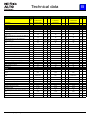
Technical data
B
NEPTUNE 4
General
Tol.
4-39FAX EU
400/3/50/
4-43FAX EU
400/3/50/16
4-50FA EU
400/3/50/13
Item no.
107146600
107146601
107146602
Technical Data
Test Result
Description
Tol. + Tol. -
Test Result
Tol. + Tol. -
Test Result
Tol. + Tol. -
Heating Unit
Boilerpower_input (kW)
61
Temperature t max, @ inlet 12° (°C)
Delta temp. variance at 50 °C, meassured at
@ gun (°C)
Boiler on time at 50 °C set point, @ inlet 12°
(sec)
Steam temperature t II @ outlet and v.
steamnozzle (°C)
Pressure P2 @ outlet v. standard nozzle
(bar)
82
+4 /
-4
78
+4 /
-4
76
+4 /
-4
30
+0 /
-3
30
+0 /
-3
30
+2 /
-3
30
+0 /
-3
30
+0 /
-3
30
+5 /
-5
140
+10 /
-30
140
+10 /
-30
140
+10 / -30
27
+5 /
-5
27
+5 /
-5
27
+5 /
-5
+0,5 /
-0
+0,5 /
-0
+0,5 /
-0
+0,5 /
-0
+0,5 /
-0
+0,5 /
-0
Fuel pump type
61
Diesel
Oil pressure ( bar )
12
Nozzle size, oil
Diesel
1,25 60°H (61659)
CO2 content min ( % )
10,5
Efficiency burner ( % )
92
66
12
Diesel
1,25 60°H (61659)
10,5
+1,5 / -0,5
92
14
1,25 60°H
10,5
+1,5 / -0,5
92
0-1
+1,5 / -0,5
Soot picture
0-1
Exhaust outlet temperature (°C)
160
+10 /
-10
160
+10 /
-10
160
0-1
+10 / -10
Exhaust temperature, cut off (°C)
270
+0 /
-12
270
+0 /
-12
270
+0 /
Fuel consump. @ dT=45 deg(kg/h)
3,4
0,0
0,1
3,6
0,0
0,1
4,0
0,0
0,1
Fuel consumption (kg/h) @ 12 °C inlet
5,2
0,0
0,0
5,2
0,0
0,0
5,7
0,0
0,0
Water volume in coil (l)
3,4
Fuel tank (l)
15
15
15
15
15
15
15
3,4
15
-12
3,4
15
Others
Gun
Lance
ST ERGO 2000
UNIVERSAL PLUS
940
ST ERGO 2000
UNIVERSAL PLUS
940
Hose
DN 8 x 15m
DN 8 x 15m
ST ERGO 2000
TORNADO PLUS
920
DN 8x10m Quick /
3/8"
NT 0450
NT 0450
NT 0500
High pressure nozzle
Noise level 1m Lpa( dBA)
80
+1,5 / -1,5
80
+1,5 / -1,5
75,6
+1,5 / -1,5
Noisepower LWA (dB) A
94
+1,5 / -1,5
94
+1,5 / -1,5
91
+1,5 / -1,5
Impact force
N
35
Vibration ISO 5349 ( m/s² )
≤ 2,5
Protection Class
IP X5
Max detergent flow from full internal tank (%)
Max detergent flow from full internal tank (L/
min)
Approved by
Approvals
NEPTUNE 4 FA_EN_Ver.2.0_ 22/11
4
0,46
39
45
≤ 2,5
IP X5 IP X5
+1 /
-1
+0,2 / -0,2
IP X5
4
0,49
≤ 2,5
IP X5 IP X5
+1 /
-1
+0,2 / -0,2
IP X5
4
0,55
SLG Chemnitz
SLG Chemnitz
SLG Chemnitz
CE, GS
CE, GS
CE, GS
IP X5 IP X5
+1 /
-1
+0,2 / -0,2
6
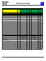
Technical data
B
NEPTUNE 4 FA
Description
Item no.
Gen.
Tol.
4-28FAX Expt
220/1/60/15
107146605
Test Result
Technical Data
4-25FAX EU
230/1/50/16
107146608
Tol. + Tol. -
Test Result
4-44FA JP 200/3/50/23
107146609
Tol. + Tol. -
Test Result
Pump-Data
Max. inlet pressure (bar)
10
10
10
Max. Inlet temperature (°C)
40
40
40
Pressure at pump head
Pressure @ Cylinder Head (bar)
Pressure @ Outlet (bar)
Pressure @ after Gun (bar)
Pressure cut off @ Cylinder Head
(bar)
Pressure Pmax safety valve
Flow. Qiec (l/min)
Flow. Qmax (l/min)
Flow. Qmin, steam (l/min)
5,50
%
5,50
%
5,50
%
5,50
%
2,90
%
5%
3,00
%
Type
99
+5 /
-5
127
+7 /
-7
156
+9 /
-9
105
+6 /
-6
133
+7 /
-7
162
+9 /
-9
90
+5 /
-5
120
+7 /
-7
157
+9 /
-9
94
+5 /
-5
110
+6 /
-6
132
+7 /
-7
125
180
+5 /
+5 /
-5
-5
140
210
+5 /
+5 /
-5
-5
182
250
+5 /
+5 /
-5
-5
9,40
+0,3 / -0,3
8,00
+0,2 / -0,2
13,50
+0,4 / -0,4
10,00
+0,5 / -0,5
8,60
+0,4 / -0,4
14,40
+0,7 / -0,7
5,10
+0,2 / -0,2
5,50
+0,2 / -0,2
5,00
+0,2 / -0,2
NA5
NA5
NA5
Ceramic
Ceramic
Ceramic
20
20
20
Pump oil type
6,1
Oil BP Energol GR-XP
220
6,1
Oil BP Energol GR-XP
220
10,2
Oil BP Energol GR-XP
220
Oil volume (l)
0,95
0,95
0,95
Piston type
Piston diameter (mm)
Stroke / Wobble disc angle
Tol. + Tol. -
Electronics
Elec. V/Ph/Hz
220V/1~/60Hz
230V/1~/50Hz
200V/3~/50Hz
Current consump. - hot (A)
14,3
+1,0 / -3,0
15
+1,0 / -3,0
18,9
+1,0 / -3,0
Current consump. - cold (A)
Power Consumption - hot (kW) hot
14,6
+1,0 / -3,0
15,5
+1,0 / -3,0
19,5
+1,0 / -3,0
3,5
+0,5 / -0,5
3,6
+0,5 / -0,5
4,8
+0,5 / -0,5
Fuse size (A)
Cord type
Plug type
Control
Control voltage
Contactor
Electrical diagram
Eletrical test data
Highvoltage (HV) test (V)
16
16
H07RN-F 4G1,5 x 6m
(CEE 3P+N+G / 16A)
H07RN-F 3G1,5 x 6m
(CEE 3P+N+G / 16A)
20
Power cord VCT
4x3,5x6m
PCB
PCB
PCB
24 Volt-Control voltage
24 Volt-Control voltage
24 Volt-Control voltage
100-C12KJ10 5,5kW
100-C12KJ10 5,5kW
100-C30 24V/50-60H
106421531
106427175
106421532
1000 Vac
1000 Vac
1000 Vac
≥ 1MΩ / 500Vdc
≥ 1MΩ / 500Vdc
≥ 1MΩ / 500Vdc
0,20
0,20
0,20
1~ Induction
1~ Induction
3~ Induction
1450
1450
1450
Class F
Class F
Class F
Protection Class
IP54
IP54
IP54
Nominal power [kW]
Cos j
2,1
0,75
2,6
0,94
4
0,75
HV-Resistance (MΩ)
Cord-resistance (Ohm)
Motor-Data
Motortype
Rotational speed [min-1]
Insulation
NEPTUNE 4 FA_EN_Ver.2.0_ 22/11
7
Technical data
B
NEPTUNE 4
Description
General
Tol.
4-28FAX Expt
220/1/60/15
Item no.
107146605
Technical Data
Test Result
4-25FAX EU
230/1/50/16
4-44FA JP
200/3/50/23
107146608
Tol. + Tol. -
Test Result
107146609
Tol. + Tol. -
Test Result
Tol. + Tol. -
Heating Unit
Boilerpower_input (kW)
48
Temperature t max, @ inlet 12° (°C)
Delta temp. variance at 50 °C, meassured at
@ gun (°C)
Boiler on time at 50 °C set point, @ inlet 12°
(sec)
Steam temperature t II @ outlet and v.
steamnozzle (°C)
Pressure P2 @ outlet v. standard nozzle
(bar)
80
+4 /
-4
92
+4 /
-4
72
+4 /
-4
30
+0 /
-3
30
+0 /
-3
30
+0 /
-3
30
+5 /
-5
30
+0 /
-3
30
+5 /
-5
140
+10 /
-30
140
+10 /
-30
140
+10 / -30
27
+5 /
-5
61
+5 /
-5
27
+5 /
-5
+0,5 /
-0
+0,5 /
-0
Fuel pump type
48
Diesel
Oil pressure ( bar )
61
Diesel
Diesel
12
1,0 60°H
(2802717)
+0,5 /
-0
12
1,0 60°H
(2802717)
+0,5 /
-0
CO2 content min ( % )
10,5
+0,5 /
-0
10,5
+0,5 /
-0
Efficiency burner ( % )
92,5
+1,5 / -0,5
92,5
+1,5 / -0,5
92
Nozzle size, oil
12
1,25 60°H
0-1
10,5
+1,5 / -0,5
Soot picture
0-1
Exhaust outlet temperature (°C)
145
+10 /
-10
145
+10 /
-10
160
0-1
+10 / -10
Exhaust temperature, cut off (°C)
270
+0 /
-12
270
+0 /
-12
270
+0 /
-12
Fuel consump. @ dT=45 deg(kg/h)
2,7
0,0
0,1
2,3
0,0
0,1
3,9
0,0
0,1
Fuel consumption (kg/h) @ 12 °C inlet
4,1
0,0
0,0
4,1
0,0
0,0
5,2
0,0
0,0
Water volume in coil (l)
3,4
Fuel tank (l)
15
15
15
3,4
15
15
15
3,4
15
15
15
Others
Gun
Lance
ST ERGO 2000
UNIVERSAL PLUS
940
ST ERGO 2000
UNIVERSAL PLUS
940
Hose
DN 8x15m
DN 8 x 15m
High pressure nozzle
NT 0450
ST ERGO 2000
TORNADO PLUS
920
DN 8x10m Quick /
3/8"
NT 0340
NT 0500
Noise level 1m Lpa( dBA)
80
+1,5 / -1,5
80
+1,5 / -1,5
75,2
+1,5 / -1,5
Noisepower LWA (dB) A
94
+1,5 / -1,5
94
+1,5 / -1,5
91
+1,5 / -1,5
Impact force
24
23
42
Vibration ISO 5349 ( m/s² )
≤ 2,5
≤ 2,5
≤ 2,5
Protection Class
IP X5
Max detergent flow from full internal tank (%)
Max detergent flow from full internal tank (L/
min)
Approved by
Approvals
NEPTUNE 4 FA_EN_Ver.2.0_ 22/11
N
4
0,38
IP X5 IP X5
+1 /
-1
+0,2 / -0,2
IP X5
4
0,32
IP X5 IP X5
+1 /
-1
+0,2 / -0,2
IP X5
4
0,54
?
SLG Chemnitz
?
CE
CE, GS
CE,
IP X5 IP X5
+1 /
-1
+0,2 / -0,2
8
Technical data
B
NEPTUNE 4 FA
Description
Item no.
Gen.
Tol. 4-44FA JP 200/3/60/20
107146610
Test Result
Technical Data
4-50FAX EU
400/3/50/13
107146611
Tol. + Tol. -
Test Result
4-50FA NO
400/230/3/50/
107146612
Tol. + Tol. -
Test Result
Pump-Data
Max. inlet pressure (bar)
10
10
10
Max. Inlet temperature (°C)
40
40
40
Pressure at pump head
Pressure @ Cylinder Head (bar)
Pressure @ Outlet (bar)
Pressure @ after Gun (bar)
Pressure cut off @ Cylinder Head
(bar)
Pressure Pmax safety valve
Flow. Qiec (l/min)
Flow. Qmax (l/min)
Flow. Qmin, steam (l/min)
5,50
%
5,50
%
5,50
%
5,50
%
2,90
%
5%
3,00
%
Type
156
+9 /
-9
175
+10 /
-10
175
+10 /
-10
162
+9 /
-9
181
+10 /
-10
181
+10 /
-10
148
+8 /
-8
166
+9 /
-9
167
+9 /
-9
132
+7 /
-7
144
+8 /
-8
142
+8 /
-8
182
250
+5 /
+5 /
-5
-5
201
250
+5 /
+5 /
-5
-5
201
250
+5 /
+5 /
-5
-5
13,60
+0,4 / -0,4
13,70
+0,4 / -0,4
13,70
+0,4 / -0,4
14,70
+0,7 / -0,7
14,60
+0,7 / -0,7
14,60
+0,7 / -0,7
5,00
+0,2 / -0,2
7,00
+0,2 / -0,2
7,00
+0,2 / -0,2
NA5
NA5
NA5
Ceramic
Ceramic
Ceramic
20
20
20
Pump oil type
8,4
Oil BP Energol GR-XP
220
10,2
Oil BP Energol GR-XP
220
10,2
Oil BP Energol GR-XP
220
Oil volume (l)
0,95
0,95
0,95
Piston type
Piston diameter (mm)
Stroke / Wobble disc angle
Tol. + Tol. -
Electronics
Elec. V/Ph/Hz
200V/3~/60Hz
400V/3~/50Hz
400/230V/3~/50Hz
Current consump. - hot (A)
16,8
+1,0 / -3,0
12,3
+1,0 / -3,0
12,2 / 22,3
+1,0 / -3,0
Current consump. - cold (A)
Power Consumption - hot (kW) hot
17,5
+1,0 / -3,0
12,6
+1,0 / -3,0
12,5 / 23
+1,0 / -3,0
4,7
+0,5 / -0,5
6,1
+0,5 / -0,5
6 / 5,8
+0,5 / -0,5
Fuse size (A)
Cord type
Plug type
Control
Control voltage
Contactor
Electrical diagram
Eletrical test data
Highvoltage (HV) test (V)
20
Power cord VCT
4x3,5x6m
16
25/16
H07RN-F 4G1,5 x 6m
CEE 3P+N+G / 16A
H07RN-F 4G2,5 x 6m
PCB
PCB
PCB
24 Volt-Control voltage
24 Volt-Control voltage
24 Volt-Control voltage
100-C30 24V/50-60H
100-C12KJ10 5,5kW
100-C12KJ10 5,5kW
106421532
106427170
106427174
1000 Vac
1000 Vac
1000 Vac
≥ 1MΩ / 500Vdc
≥ 1MΩ / 500Vdc
≥ 1MΩ / 500Vdc
0,20
0,20
0,20
3~ Induction
3~ Induction
3~ Induction
1450
1450
1450
Class F
Class F
Class F
Protection Class
IP54
IP54
IP54
Nominal power [kW]
Cos j
4
0,75
5,5
0,75
5,5
0,75
HV-Resistance (MΩ)
Cord-resistance (Ohm)
Motor-Data
Motortype
Rotational speed [min-1]
Insulation
NEPTUNE 4 FA_EN_Ver.2.0_ 22/11
9
Technical data
B
NEPTUNE 4
General
Tol.
4-44FA JP
200/3/60/20
4-50FAX EU
400/3/50/13
4-50FA NO
400/230/3/50/
Item no.
107146610
107146611
107146612
Technical Data
Test Result
Description
Tol. + Tol. -
Test Result
Tol. + Tol. -
Test Result
Tol. + Tol. -
Heating Unit
Boilerpower_input (kW)
61
Temperature t max, @ inlet 12° (°C)
Delta temp. variance at 50 °C, meassured at
@ gun (°C)
Boiler on time at 50 °C set point, @ inlet 12°
(sec)
Steam temperature t II @ outlet and v.
steamnozzle (°C)
Pressure P2 @ outlet v. standard nozzle
(bar)
71
+4 /
-4
76
+4 /
-4
76
+4 /
-4
30
+0 /
-3
30
+2 /
-3
30
+2 /
-3
30
+5 /
-5
30
+5 /
-5
30
+5 /
-5
140
+10 /
-30
140
+10 /
-30
140
+10 / -30
27
+5 /
-5
27
+5 /
-5
27
+5 /
-5
+0,5 /
-0
+0,5 /
-0
+0,5 /
-0
+0,5 /
-0
+0,5 /
-0
+0,5 /
-0
Fuel pump type
66
Diesel
Oil pressure ( bar )
12
Nozzle size, oil
Diesel
1,25 60°H
CO2 content min ( % )
10,5
Efficiency burner ( % )
92
66
14
Diesel
1,25 60°H
10,5
+1,5 / -0,5
92
14
1,25 60°H
10,5
+1,5 / -0,5
92
0-1
+1,5 / -0,5
Soot picture
0-1
Exhaust outlet temperature (°C)
160
+10 /
-10
160
+10 /
-10
160
0-1
+10 / -10
Exhaust temperature, cut off (°C)
270
+0 /
-12
270
+0 /
-12
270
+0 /
Fuel consump. @ dT=45 deg(kg/h)
4,0
0,0
0,1
4,0
0,0
0,1
4,0
0,0
0,1
Fuel consumption (kg/h) @ 12 °C inlet
5,2
0,0
0,0
5,7
0,0
0,0
5,7
0,0
0,0
Water volume in coil (l)
3,4
Fuel tank (l)
15
15
15
15
15
15
15
3,4
15
-12
3,4
15
Others
Gun
ST ERGO 2000
TORNADO PLUS
920
DN 8x10m Quick /
3/8"
Lance
Hose
High pressure nozzle
Noisepower LWA (dB) A
N
+1,5 / -1,5
91
+1,5 / -1,5
42
≤ 2,5
Protection Class
IP X5
Max detergent flow from full internal tank (%)
Max detergent flow from full internal tank (L/
min)
Approved by
Approvals
NEPTUNE 4 FA_EN_Ver.2.0_ 22/11
NT 0500
75,2
Vibration ISO 5349 ( m/s² )
4
0,54
ST ERGO 2000
TORNADO PLUS
920
DN 8x10m Quick /
3/8"
DN 8x15m
NT 0500
Noise level 1m Lpa( dBA)
Impact force
ST ERGO 2000
TORNADO PLUS
920
NT 0500
75,6
+1,5 / -1,5
91
+1,5 / -1,5
45
+1 /
-1
+0,2 / -0,2
IP X5
4
0,55
+1,5 / -1,5
91
+1,5 / -1,5
45
≤ 2,5
IP X5 IP X5
75,6
≤ 2,5
IP X5 IP X5
+1 /
-1
+0,2 / -0,2
IP X5
4
0,55
?
SLG Chemnitz
SLG Chemnitz
CE,
CE, GS
CE, GS
IP X5 IP X5
+1 /
-1
+0,2 / -0,2
10
Technical data
B
NEPTUNE 4 FA
Description
Gen.
Tol.
4-50FAX NO
400/230/3/50/
Item no.
107146613
Technical Data
Test Result
4-55FA EU
400/3/50/14
4-55FAX EU
400/3/50/14
107146614
Tol. + Tol. -
Test Result
107146615
Tol. + Tol. -
Test Result
Pump-Data
Max. inlet pressure (bar)
10
10
10
Max. Inlet temperature (°C)
40
40
40
Pressure at pump head
Pressure @ Cylinder Head (bar)
Pressure @ Outlet (bar)
Pressure @ after Gun (bar)
Pressure cut off @ Cylinder Head
(bar)
5,50
%
5,50
%
5,50
%
5,50
%
Pressure Pmax safety valve
Flow. Qiec (l/min)
Flow. Qmax (l/min)
Flow. Qmin, steam (l/min)
2,90
%
5%
3,00
%
Type
Piston type
Piston diameter (mm)
175
+10 /
-10
185
+10 /
-10
185
+10 /
-10
181
+10 /
-10
191
+10 /
-10
191
+10 /
-10
171
+9 /
-9
177
+10 /
-10
176
+10 /
-10
144
+8 /
-8
160
+9 /
-9
162
+9 /
-9
201
+5 /
-5
211
+5 /
-5
211
+5 /
-5
250
+5 /
-5
250
+5 /
-5
250
+5 /
-5
13,70
+0,4 / -0,4
14,50
+0,4 / -0,4
14,50
+0,4 / -0,4
14,60
+0,7 / -0,7
15,30
+0,8 / -0,8
15,30
+0,8 / -0,8
7,00
+0,2 / -0,2
7,00
+0,2 / -0,2
7,50
+0,2 / -0,2
NA5
NA5
NA5
Ceramic
Ceramic
Ceramic
20
20
20
Pump oil type
10,2
Oil BP Energol GR-XP
220
10,9
Oil BP Energol GR-XP
220
10,9
Oil BP Energol GR-XP
220
Oil volume (l)
0,95
0,95
0,95
Stroke / Wobble disc angle
Tol. + Tol. -
Electronics
Elec. V/Ph/Hz
400/230V/3~/50Hz
400V/3~/50Hz
400V/3~/50Hz
Current consump. - hot (A)
12,4 / 22,5
+1,0 / -3,0
12,5
+1,0 / -3,0
12,6
+1,0 / -3,0
Current consump. - cold (A)
Power Consumption - hot (kW) hot
12,6 / 23,2
+1,0 / -3,0
12,8
+1,0 / -3,0
12,7
+1,0 / -3,0
6,2 / 6
+0,5 / -0,5
6,3
+0,5 / -0,5
6,4
+0,5 / -0,5
Fuse size (A)
Cord type
25/16
16
16
H07RN-F 4G2,5 x 6m
H07RN-F 4G1,5 x 6m
H07RN-F 4G1,5 x 6m
CEE 3P+N+G / 16A
CEE 3P+N+G / 16A
Plug type
Control
Control voltage
Contactor
Electrical diagram
Eletrical test data
Highvoltage (HV) test (V)
PCB
PCB
PCB
24 Volt-Control voltage
24 Volt-Control voltage
24 Volt-Control voltage
100-C12KJ10 5,5kW
100-C12KJ10 5,5kW
100-C12KJ10 5,5kW
1064271474
106427170
106427170
1000 Vac
1000 Vac
1000 Vac
≥ 1MΩ / 500Vdc
≥ 1MΩ / 500Vdc
≥ 1MΩ / 500Vdc
0,20
0,20
0,20
3~ Induction
3~ Induction
3~ Induction
1450
1450
1450
Class F
Class F
Class F
Protection Class
IP54
IP54
IP54
Nominal power [kW]
Cos j
5,5
0,75
5,5
0,75
5,5
0,75
HV-Resistance (MΩ)
Cord-resistance (Ohm)
Motor-Data
Motortype
Rotational speed [min-1]
Insulation
NEPTUNE 4 FA_EN_Ver.2.0_ 22/11
11
Technical data
B
NEPTUNE 4
General
Tol.
4-50FAX NO
400/230/3/50/
4-55FA EU
400/3/50/14
4-55FAX EU
400/3/50/14
Item no.
107146613
107146614
107146615
Technical Data
Test Result
Description
Tol. + Tol. -
Test Result
Tol. + Tol. -
Test Result
Tol. + Tol. -
Heating Unit
Boilerpower_input (kW)
66
Temperature t max, @ inlet 12° (°C)
Delta temp. variance at 50 °C, meassured at
@ gun (°C)
Boiler on time at 50 °C set point, @ inlet 12°
(sec)
Steam temperature t II @ outlet and v.
steamnozzle (°C)
Pressure P2 @ outlet v. standard nozzle
(bar)
76
+4 /
-4
72
+4 /
-4
72
+4 /
-4
30
+2 /
-3
30
+2 /
-3
30
+2 /
-3
30
+5 /
-5
30
+5 /
-5
30
+5 /
-5
140
+10 /
-30
140
+10 /
-30
140
+10 / -30
27
+5 /
-5
27
+5 /
-5
27
+5 /
-5
+0,5 /
-0
+0,5 /
-0
+0,5 /
-0
+0,5 /
-0
+0,5 /
-0
+0,5 /
-0
Fuel pump type
66
Diesel
Oil pressure ( bar )
14
Nozzle size, oil
Diesel
1,25 60°H
CO2 content min ( % )
10,5
Efficiency burner ( % )
92
66
14
Diesel
1,25 60°H
10,5
+1,5 / -0,5
92
14
1,25 60°H
10,5
+1,5 / -0,5
92
0-1
+1,5 / -0,5
Soot picture
0-1
Exhaust outlet temperature (°C)
160
+10 /
-10
160
+10 /
-10
160
0-1
+10 / -10
Exhaust temperature, cut off (°C)
270
+0 /
-12
270
+0 /
-12
270
+0 /
Fuel consump. @ dT=45 deg(kg/h)
4,0
0,0
0,1
4,2
0,0
0,1
4,2
0,0
0,1
Fuel consumption (kg/h) @ 12 °C inlet
5,7
0,0
0,0
5,7
0,0
0,0
5,7
0,0
0,0
Water volume in coil (l)
3,4
Fuel tank (l)
15
15
15
15
15
15
15
3,4
15
-12
3,4
15
Others
Gun
Lance
ST ERGO 2000
TORNADO PLUS
920
Hose
DN 8x15m
ST ERGO 2000
TORNADO PLUS
920
DN 8x10m Quick /
3/8"
NT 0500
NT 0550
High pressure nozzle
Noise level 1m Lpa( dBA)
Noisepower LWA (dB) A
Impact force
N
75,6
+1,5 / -1,5
91
+1,5 / -1,5
45
Vibration ISO 5349 ( m/s² )
≤ 2,5
Protection Class
IP X5
Max detergent flow from full internal tank (%)
Max detergent flow from full internal tank (L/
min)
Approved by
Approvals
NEPTUNE 4 FA_EN_Ver.2.0_ 22/11
4
0,55
ST ERGO 2000
TORNADO PLUS
920
DN 8x15m
NT 0500
77,1
+1,5 / -1,5
92
+1,5 / -1,5
49
+1 /
-1
+0,2 / -0,2
IP X5
4
0,58
+1,5 / -1,5
92
+1,5 / -1,5
49
≤ 2,5
IP X5 IP X5
77,1
≤ 2,5
IP X5 IP X5
+1 /
-1
+0,2 / -0,2
IP X5
4
0,58
SLG Chemnitz
SLG Chemnitz
SLG Chemnitz
CE, GS
CE, GS
CE, GS
IP X5 IP X5
+1 /
-1
+0,2 / -0,2
12
Technical data
B
NEPTUNE 4 FA
Description
Gen.
Tol.
4-55FA Expt
220/440/3/60/23/14
Item no.
107146616
Technical Data
Test Result
4-55FAX Expt
220/440/3/60/23/14
4-36FAX USA
230/1/60/30
107146617
Tol. + Tol. -
Test Result
107146618
Tol. + Tol. -
Test Result
Pump-Data
Max. inlet pressure (bar)
10
10
10
Max. Inlet temperature (°C)
40
40
40
Pressure at pump head
Pressure @ Cylinder Head (bar)
Pressure @ Outlet (bar)
Pressure @ after Gun (bar)
Pressure cut off @ Cylinder Head
(bar)
5,50
%
5,50
%
5,50
%
5,50
%
Pressure Pmax safety valve
Flow. Qiec (l/min)
Flow. Qmax (l/min)
Flow. Qmin, steam (l/min)
2,90
%
5%
3,00
%
Type
Piston type
Piston diameter (mm)
185
+10 /
-10
185
+10 /
-10
165
+9 /
-9
191
+10 /
-10
191
+10 /
-10
171
+9 /
-9
175
+10 /
-10
179
+10 /
-10
160
+9 /
-9
155
+9 /
-9
157
+9 /
-9
155
+9 /
-9
211
+5 /
-5
211
+5 /
-5
191
+5 /
-5
250
+5 /
-5
250
+5 /
-5
250
+5 /
-5
14,50
+0,4 / -0,4
14,50
+0,4 / -0,4
11,10
+0,3 / -0,3
15,30
+0,8 / -0,8
15,30
+0,8 / -0,8
12,10
+0,6 / -0,6
7,50
+0,2 / -0,2
7,50
+0,2 / -0,2
7,00
+0,2 / -0,2
NA5
NA5
NA5
Ceramic
Ceramic
Ceramic
20
20
20
Pump oil type
9,15
Oil BP Energol GR-XP
220
9,15
Oil BP Energol GR-XP
220
7,2
Oil BP Energol GR-XP
220
Oil volume (l)
0,95
0,95
0,95
Stroke / Wobble disc angle
Tol. + Tol. -
Electronics
Elec. V/Ph/Hz
440-220V/3~/60Hz
440-220V/3~/60Hz
230V/1~/60Hz
Current consump. - hot (A)
22,4 / 12,2
+1,0 / -3,0
22,5 / 12,4
+1,0 / -3,0
25,3
+1,0 / -3,0
Current consump. - cold (A)
Power Consumption - hot (kW) hot
23,4 / 12,6
+1,0 / -3,0
23,4 / 12,8
+1,0 / -3,0
26,8
+1,0 / -3,0
6,3 / 6,5
+0,5 / -0,5
6,4 / 6,6
+0,5 / -0,5
7
+0,5 / -0,5
Fuse size (A)
Cord type
24/16
24/16
30
H07RN-F 4G2,5 x 6m
H07RN-F 4G2,5 x 6m
SJOW AWG10/3X9.0
PCB
PCB
PCB
24 Volt-Control voltage
24 Volt-Control voltage
24 Volt-Control voltage
100-C12KJ10 5,5kW
100-C12KJ10 5,5kW
CJX2D-B32
106427174
106427174
106420541
Plug type
Control
Control voltage
Contactor
Electrical diagram
Eletrical test data
Highvoltage (HV) test (V)
NEMA 6-30P
1000 Vac
1000 Vac
1000 Vac
≥ 1MΩ / 500Vdc
≥ 1MΩ / 500Vdc
≥ 1MΩ / 500Vdc
0,20
0,20
0,20
3~ Induction
3~ Induction
1~ Induction
1450
1450
1450
Class F
Class F
Class F
Protection Class
IP54
IP54
IP54
Nominal power [kW]
Cos j
5,5
0,75
5,5
0,75
5,5
0,75
HV-Resistance (MΩ)
Cord-resistance (Ohm)
Motor-Data
Motortype
Rotational speed [min-1]
Insulation
NEPTUNE 4 FA_EN_Ver.2.0_ 22/11
13
Technical data
B
NEPTUNE 4
Description
Gene4-55FA Expt
ral 220/440/3/60/23/1
Tol.
4
Item no.
107146616
Technical Data
Test Result
Tol. + Tol. -
4-55FAX Expt
220/440/3/60/23/1
4
4-36FAX USA
230/1/60/30
107146617
107146618
Test Result
Tol. + Tol. -
Test Result
Tol. + Tol. -
Heating Unit
Boilerpower_input (kW)
66
Temperature t max, @ inlet 12° (°C)
Delta temp. variance at 50 °C, meassured at
@ gun (°C)
Boiler on time at 50 °C set point, @ inlet 12°
(sec)
Steam temperature t II @ outlet and v.
steamnozzle (°C)
Pressure P2 @ outlet v. standard nozzle
(bar)
72
+4 /
-4
72
+4 /
-4
85
+4 /
-4
30
+0 /
-3
30
+0 /
-3
30
+0 /
-3
30
+5 /
-5
30
+5 /
-5
30
+5 /
-5
140
+10 /
-30
140
+10 /
-30
140
+10 /
-30
27
+5 /
-5
27
+5 /
-5
27
+5 /
-5
+0,5 /
-0
+0,5 /
-0
+0,5 /
-0
+0,5 /
-0
+0,5 /
-0
+0,5 /
-0
Fuel pump type
66
Diesel
Oil pressure ( bar )
14
Nozzle size, oil
Diesel
1,25 60°H
CO2 content min ( % )
10,5
Efficiency burner ( % )
92
61
14
Diesel
1,25 60°H
10,5
+1,5 / -0,5
92
12
1,25 60°H (61659)
10,5
+1,5 / -0,5
92
0-1
+1,5 / -0,5
Soot picture
0-1
Exhaust outlet temperature (°C)
160
+10 /
-10
160
+10 /
-10
160
0-1
+10 /
-10
Exhaust temperature, cut off (°C)
270
+0 /
-12
270
+0 /
-12
270
+0 /
-12
Fuel consump. @ dT=45 deg(kg/h)
4,2
0,0
0,1
4,2
0,0
0,1
3,2
0,0
0,1
Fuel consumption (kg/h) @ 12 °C inlet
5,7
0,0
0,0
5,7
0,0
0,0
5,2
0,0
0,0
Water volume in coil (l)
3,4
Fuel tank (l)
15
15
15
15
15
15
15
3,4
15
3,4
15
Others
Gun
Lance
Hose
High pressure nozzle
ST ERGO 2000
TORNADO PLUS
920
DN 8x10m Quick /
3/8"
ST ERGO 2000
TORNADO PLUS
920
DN 8x15m
ST ERGO 2000
UNIVERSAL PLUS
940
DN 8x15m Quick /
3/8"
NT 0550
NT 0550
NT 0400
Noise level 1m Lpa( dBA)
77,1
+1,5 / -1,5
77,1
+1,5 / -1,5
80
+1,5 / -1,5
Noisepower LWA (dB) A
92
+1,5 / -1,5
92
+1,5 / -1,5
94
+1,5 / -1,5
Impact force
N
49
Vibration ISO 5349 ( m/s² )
≤ 2,5
Protection Class
IP X5
Max detergent flow from full internal tank (%)
Max detergent flow from full internal tank (L/
min)
Approved by
Approvals
NEPTUNE 4 FA_EN_Ver.2.0_ 22/11
4
0,58
49
35
≤ 2,5
IP X5 IP X5
+1 /
-1
+0,2 / -0,2
IP X5
4
0,58
≤ 2,5
IP X5 IP X5
+1 /
-1
+0,2 / -0,2
IP X5
4
0,44
?
?
?
CE
CE
CE,
IP X5 IP X5
+1 /
-1
+0,2 / -0,2
14
Technical data
B
NEPTUNE 4 FA
Description
Gen.
Tol. 4-28FA Gerni 240/1/50/15
Item no.
107146619
Technical Data
Test Result
4-50FAX Gerni 400/3/50/
107146620
Tol. + Tol. -
Test Result
Tol. + Tol. -
Pump-Data
Max. inlet pressure (bar)
10
10
Max. Inlet temperature (°C)
40
40
Pressure at pump head
5,50%
99
+5 /
-5
175
+10 /
-10
Pressure @ Cylinder Head (bar)
5,50%
105
+6 /
-6
181
+10 /
-10
Pressure @ Outlet (bar)
5,50%
90
+5 /
-5
171
+9 /
-9
Pressure @ after Gun (bar)
Pressure cut off @ Cylinder Head
(bar)
5,50%
86
+5 /
-5
144
+8 /
-8
130
+5 /
-5
201
+5 /
-5
180
+5 /
-5
250
+5 /
-5
2,90%
9,55
+0,3 /
-0,3
13,70
+0,4 /
-0,4
5%
10,25
+0,5 /
-0,5
14,60
+0,7 /
-0,7
3,00%
5,10
+0,2 /
-0,2
7,00
+0,2 /
-0,2
Pressure Pmax safety valve
Flow. Qiec (l/min)
Flow. Qmax (l/min)
Flow. Qmin, steam (l/min)
Type
Piston type
Piston diameter (mm)
NA5
NA5
Ceramic
Ceramic
20
20
Pump oil type
7,2
Oil BP Energol GR-XP
220
10,2
Oil BP Energol GR-XP
220
Oil volume (l)
0,95
0,95
240V/1~/50Hz
400V/3~/50Hz
Stroke / Wobble disc angle
Electronics
Elec. V/Ph/Hz
Current consump. - hot (A)
14
+1,0 /
-3,0
12,3
+1,0 /
-3,0
Current consump. - cold (A)
15
+1,0 /
-3,0
12,6
+1,0 /
-3,0
Power Consumption - hot (kW) - hot
2,7
+0,5 /
-0,5
6,1
+0,5 /
-0,5
Fuse size (A)
15
16
Cord type
H07RN-F 4G1,5 x 6m
H07RN-F 4G1,5 x 6m
Plug type
AS3112 (AU; 15A )
CEE 3P+N+G / 16A
Control
Control voltage
Contactor
Electrical diagram
PCB
PCB
24 Volt-Control voltage
24 Volt-Control voltage
100-C12KJ10 5,5kW
100-C12KJ10 5,5kW
106427175
106427170
Eletrical test data
Highvoltage (HV) test (V)
HV-Resistance (MΩ)
Cord-resistance (Ohm)
1000 Vac
1000 Vac
≥ 1MΩ / 500Vdc
≥ 1MΩ / 500Vdc
0,20
0,20
1~ Induction
3~ Induction
1450
1450
Class F
Class F
Motor-Data
Motortype
Rotational speed [min-1]
Insulation
Protection Class
IP54
Nominal power [kW]
2,6
Cos j
0,89
NEPTUNE 4 FA_EN_Ver.2.0_ 22/11
IP54
3
5,5
0,75
15
Technical data
B
NEPTUNE 4
4-28FA Gerni
240/1/50/15
4-50FAX Gerni
400/3/50/
Item no.
107146619
107146620
Technical Data
Test Result
Description
General
Tol.
Tol. +
Tol. -
Test Result
Tol. +
Tol. -
Heating Unit
Boilerpower_input (kW)
48
Temperature t max, @ inlet 12° (°C)
79
+4 /
-4
76
+4 /
-4
Delta temp. variance at 50 °C, meassured at @ gun (°
30
+0 /
-3
30
+2 /
-3
Boiler on time at 50 °C set point, @ inlet 12° (sec)
Steam temperature t II @ outlet and v. steamnozzle (°
C)
30
+5 /
-5
30
+5 /
-5
140
+10 /
-30
140
+10 /
-30
27
+5 /
-5
27
+5 /
-5
+0,5 /
-0
10,5
+0,5 /
-0
92
+1,5 /
-0,5
Pressure P2 @ outlet v. standard nozzle (bar)
Fuel pump type
66
Diesel
Oil pressure ( bar )
12
Nozzle size, oil
Diesel
+0,5 /
-0
1,0 60°H (2802717)
14
1,25 60°H
CO2 content min ( % )
10,5
+0,5 /
-0
Efficiency burner ( % )
92,5
+1,5 /
-0,5
Soot picture
0-1
Exhaust outlet temperature (°C)
145
+10 /
-10
160
+10 /
-10
Exhaust temperature, cut off (°C)
270
+0 /
-12
270
+0 /
-12
Fuel consump. @ dT=45 deg(kg/h)
2,8
0,0
0,1
4,0
0,0
0,1
107,0
0,0
0,0
5,7
0,0
0,0
15
15
75,6
+1,5 /
-1,5
91
+1,5 /
-1,5
Fuel consumption (kg/h) @ 12 °C inlet
Water volume in coil (l)
3,4
Fuel tank (l)
15
0-1
3,4
15
15
15
Others
Gun
ST ERGO 2000
ST ERGO 2000
Lance
UNIVERSAL PLUS 940
TORNADO PLUS 920
Hose
DN 8x10m Quick / 3/8"
DN 8x15m
High pressure nozzle
NT 0450
Noise level 1m Lpa( dBA)
Noisepower LWA (dB) A
Impact force
+1,5 /
-1,5
94
+1,5 /
-1,5
24
45
Vibration ISO 5349 ( m/s² )
≤ 2,5
≤ 2,5
Protection Class
IP X5
IP X5
IP X5
IP X5
IP X5
IP X5
4
+1 /
-1
4
+1 /
-1
0,38
+0,2 /
-0,2
0,55
+0,2 /
-0,2
Max detergent flow from full internal tank (%)
Max detergent flow from full internal tank (L/min)
Approved by
Approvals
NEPTUNE 4 FA_EN_Ver.2.0_ 22/11
N
NT 0500
80
SLG Chemnitz
(SLG Chemnitz) ?
CE, GS
CE, (GS)
16
Technical data
B
NEPTUNE 4 FA
Description
Gen.
Tol.
4-50FA Expt
220/440/3/60/
Item no.
107146622
Technical Data
Test Result
4-55FAX EU
400/3/50/14
4-39FAX EU 400/3/50/
107146625
Tol. + Tol. -
Test Result
107146626
Tol. + Tol. -
Test Result
Tol. + Tol. -
Pump-Data
Max. inlet pressure (bar)
10
10
10
Max. Inlet temperature (°C)
40
40
40
Pressure at pump head
Pressure @ Cylinder Head (bar)
Pressure @ Outlet (bar)
Pressure @ after Gun (bar)
Pressure cut off @ Cylinder Head
(bar)
5,50
%
5,50
%
5,50
%
5,50
%
Pressure Pmax safety valve
Flow. Qiec (l/min)
Flow. Qmax (l/min)
Flow. Qmin, steam (l/min)
2,90
%
5%
3,00
%
Type
175
+10 /
-10
152
+8 /
-8
185
+10 /
-10
181
+10 /
-10
158
+9 /
-9
191
+10 /
-10
171
+9 /
-9
140
+8 /
-8
176
+10 /
-10
142
+8 /
-8
126
+7 /
-7
162
+9 /
-9
201
+5 /
-5
178
+5 /
-5
211
+5 /
-5
250
+5 /
-5
250
+5 /
-5
250
+5 /
-5
13,90
+0,4 / -0,4
11,55
+0,3 / -0,3
14,50
+0,4 / -0,4
14,70
+0,7 / -0,7
12,50
+0,6 / -0,6
15,30
+0,8 / -0,8
7,00
+0,2 / -0,2
6,00
+0,2 / -0,2
7,50
+0,2 / -0,2
NA5
NA5
NA5
Ceramic
Ceramic
Ceramic
20
20
20
Pump oil type
8,4
Oil BP Energol GR-XP
220
8,7
Oil BP Energol GR-XP
220
10,9
Oil BP Energol GR-XP
220
Oil volume (l)
0,95
0,95
0,95
Piston type
Piston diameter (mm)
Stroke / Wobble disc angle
Electronics
Elec. V/Ph/Hz
220/440V/3~/60Hz
400V/3~/50Hz
400V/3~/50Hz
Current consump. - hot (A)
22,3 / 12,2
+1,0 / -3,0
9,2
+1,0 / -3,0
12,6
+1,0 / -3,0
Current consump. - cold (A)
Power Consumption - hot (kW) hot
23,5 / 12,7
+1,0 / -3,0
10
+1,0 / -3,0
12,7
+1,0 / -3,0
5,8 / 6
+0,5 / -0,5
4,7
+0,5 / -0,5
6,4
+0,5 / -0,5
Fuse size (A)
Cord type
24/16
16
16
H07RN-F 4G2,5 x 6m
H07RN-F 3G1,5 x 6m
H07RN-F 4G1,5 x 6m
CEE7 / 16A Schuko
CEE 3P+N+G / 16A
Plug type
Control
Control voltage
Contactor
Electrical diagram
PCB
PCB
PCB
24 Volt-Control voltage
24 Volt-Control voltage
24 Volt-Control voltage
100-C12KJ10 5,5kW
100-C12KJ10 5,5kW
100-C12KJ10 5,5kW
106427174
106427170
106427170
Eletrical test data
Highvoltage (HV) test (V)
HV-Resistance (MΩ)
Cord-resistance (Ohm)
1000 Vac
1000 Vac
1000 Vac
≥ 1MΩ / 500Vdc
≥ 1MΩ / 500Vdc
≥ 1MΩ / 500Vdc
0,20
0,20
0,20
3~ Induction
3~ Induction
3~ Induction
1450
1450
1450
Class F
Class F
Class F
IP54
Motor-Data
Motortype
Rotational speed [min-1]
Insulation
Protection Class
IP54
IP54
Nominal power [kW]
5,5
4
5,5
Cos j
0,75
0,75
0,75
NEPTUNE 4 FA_EN_Ver.2.0_ 22/11
17
Technical data
B
NEPTUNE 4
General
Tol.
4-50FA Expt
220/440/3/60/
4-39FAX EU
400/3/50/
4-55FAX EU
400/3/50/14
Item no.
107146622
107146625
107146626
Technical Data
Test Result
Description
Tol. + Tol. -
Test Result
Tol. + Tol. -
Test Result
Tol. + Tol. -
Heating Unit
Boilerpower_input (kW)
66
Temperature t max, @ inlet 12° (°C)
Delta temp. variance at 50 °C, meassured at
@ gun (°C)
Boiler on time at 50 °C set point, @ inlet 12°
(sec)
Steam temperature t II @ outlet and v.
steamnozzle (°C)
Pressure P2 @ outlet v. standard nozzle
(bar)
75
+4 /
-4
82
+4 /
-4
72
+4 /
-4
30
+0 /
-3
30
+0 /
-3
30
+2 /
-3
30
+5 /
-5
30
+0 /
-3
30
+5 /
-5
140
+10 /
-30
140
+10 /
-30
140
+10 / -30
27
+5 /
-5
27
+5 /
-5
27
+5 /
-5
+0,5 /
-0
+0,5 /
-0
+0,5 /
-0
+0,5 /
-0
+0,5 /
-0
+0,5 /
-0
Fuel pump type
61
Diesel
Oil pressure ( bar )
14
Nozzle size, oil
Diesel
1,25 60°H
CO2 content min ( % )
10,5
Efficiency burner ( % )
92
66
12
Diesel
1,25 60°H (61659)
10,5
+1,5 / -0,5
92
14
1,25 60°H
10,5
+1,5 / -0,5
92
0-1
+1,5 / -0,5
Soot picture
0-1
Exhaust outlet temperature (°C)
160
+10 /
-10
145
+10 /
-10
160
0-1
+10 / -10
Exhaust temperature, cut off (°C)
270
+0 /
-12
270
+0 /
-12
270
+0 /
-12
Fuel consump. @ dT=45 deg(kg/h)
4,1
0,0
0,1
3,4
0,0
0,1
4,2
0,0
0,1
Fuel consumption (kg/h) @ 12 °C inlet
5,7
0,0
0,0
5,2
0,0
0,0
5,7
0,0
0,0
Water volume in coil (l)
3,4
Fuel tank (l)
15
15
15
15
15
15
15
3,4
15
3,4
15
Others
Gun
Lance
ST ERGO 2000
TORNADO PLUS
920
ST ERGO 2000
UNIVERSAL PLUS
940
ST ERGO 2000
TORNADO PLUS
920
Hose
DN 8x15m
DN 8 x 15m
DN 8x15m
High pressure nozzle
NT 0550
NT 0450
NT 0500
Noise level 1m Lpa( dBA)
75,6
+1,5 / -1,5
80
+1,5 / -1,5
77,1
+1,5 / -1,5
Noisepower LWA (dB) A
91
+1,5 / -1,5
94
+1,5 / -1,5
92
+1,5 / -1,5
Impact force
45
35
49
Vibration ISO 5349 ( m/s² )
≤ 2,5
≤ 2,5
≤ 2,5
Protection Class
IP X5
Max detergent flow from full internal tank (%)
Max detergent flow from full internal tank (L/
min)
Approved by
Approvals
NEPTUNE 4 FA_EN_Ver.2.0_ 22/11
N
4
0,56
IP X5 IP X5
+1 /
-1
+0,2 / -0,2
IP X5
4
0,46
IP X5 IP X5
+1 /
-1
+0,2 / -0,2
IP X5
4
0,58
?
SLG Chemnitz
SLG Chemnitz
CE
CE, GS
CE, GS
IP
IP X5 X5
+1 /
-1
+0,2 / -0,2
18
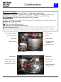
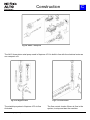
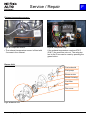
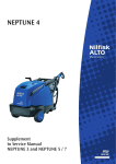
Construction
C
Neptune 4 FA Variants.
Single phase: 4-28FAX Expt, 4-31 FAX EU, 4-37FAX USA, 4-28FA Gerni.
Three phase: 4-39FAX EU, 4-43FAX EU, 4-47FA JP, 4-50FA EU, 4-50FAX EU, 4-50FA NO,
4-55FA EU, 4-55FAX EU, 4-55FA Expt, 4-55FAX Expt, 4-55FAX Gerni, 4-50FA Expt.
X vs. Standard : Hose Reel and Hose lenght 15m on X models.
_ : These numbers refer to the theoretical total impact of spraying water calculated by the formula:
Impact = Q1 x √ P1 x 0.24 [ N ]
P1 = bar. Q1 = l/min.v P1.
FA: Flow activated start/stop system
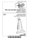
The Neptune 4 FA is build with an NA5 pump.
The by-pass system is flow activated, unlike the pressure activated by-pass system known from
previous Neptune machines.
The frame, cabinet, detergent tank and fuel tank is identical to previous Neptune 3 / 4 models.
Burner fan housing
Fuel pump
Anti scale pump
Boiler
Fuel filter
Flow control
Safety valve
Pressure/water
regulation
By-pass valve
Fig.C.1: Side view
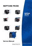
Electrodes
Boiler inlet
Ignition transformer
Flame sensor
Boiler outlet—with
temperature sensor
Fuel nozzle
Exhaust thermal
safety sensor
Fig.C.2: Top view
NEPTUNE 4 FA_EN_Ver.2.0_ 22/11
17
Construction
C
Lance holder
Handle
Top cover
Fuel filter
Fuel tank
Side cabinet—right
Side cabinet—left
Detergent tank
Water break tank
External detergent
Fig.C.3: Frame & cabinet parts
NEPTUNE 4 FA_EN_Ver.2.0_ 22/11
18
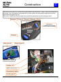
Construction
C
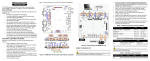
The electric box (Fig.C.6) contains the control board, the transformer, relays, fuses,and connection
terminals. The cover plate is mounted with the main switch, the temperature adjustment and five
status/warningLights (Fig.C.4).
The cover is sealed around the edge and around the manometer and the detergent valve.
Operation
Pump oil
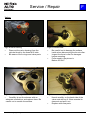
Service
Antistone
Fuel
Adjustment:
Temperature settings
Service interval settings
Detergent
Fig.C.4: Operation panel
Main switch S1
Display board A2
Fig.C.5: Panel - inside
Contactor K1
Ignition transformer T1
Exhaust temp. switch
Control board A1
NEPTUNE 4 FA_EN_Ver.2.0_ 22/11
Fig.C.6: Electrical box
19
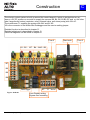
Construction
C
The electric control system is built up around the control board A1 which is divided into two systems, a 5V DC system on one side to supply the sensors B8, B4, B6, B1,B9, B7 and on the other
side it supplies the actors (contactor, relay, solenoid valve, anti stone pump) with 24V AC.
The transformer T1 supplies the system with 24V and 8V AC.
X2 is the connector to the Nilfisk-Alto Datalogger and the service setting jumper.
Detailed function is described in chapter D.
Detailed adjustment is described in chapter G.
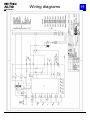
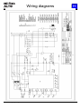
Electrical diagrams can be found in chapter H.
Fuse 2
Start knob
Fuse 3
B1 - B2 - MT - B4 - 24AC - B3
B7
B6
B9
B8
Data logger
Fig.C.7: PCB A1
NEPTUNE 4 FA_EN_Ver.2.0_ 22/11
K1 - Y1 - 8VAC
Hour Display setting
Bypass time canceling
20
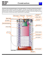
Construction
C
The boiler is the heat generating part of a hot water machine. It consists of a labyrinth-constructed
tube coil, which encloses the combustion chamber. The tube coil is enclosed by a double container
with boiler jacket, bottom, and top in a sandwich construction, between which the combustion air is
routed into the combustion. An insulating material placed in the bottom of the boiler makes sure that
the inner bottom, among other things, is protected from superheating.
Flame sensor
Electrodes
Fuel nozzle
Exhaust
Water outlet
Water inlet
Top plate
Air distribu-
Flame tube top part
Burner tube
Flame tube
Air inlet
Fixation spacer
Outer jacket
Inner jacket
Mounting plate
Fig.C.8: Boiler
Insolation
NEPTUNE 4 FA_EN_Ver.2.0_ 22/11
21
Construction
C
Fig.C.9: Motor - Pump unit
The NA 5 three piston axial pump used in Neptune 4 FA is build in line with the electrical motor as
one compact unit.
Fig.C.10: By-pass valve
The start/stop system in Neptune 4 FA is flow
Activated.
NEPTUNE 4 FA_EN_Ver.2.0_ 22/11
Fig.C.11: Flow control
The flow control checks if there is flow in the
system, to stop and start the machine.
22
Function
D
If the machine and the power supply are working correcdtly the following will happend during start
up.
Start - cold
Start - hot
Status indicators
Detergent valve
Fig.D.1: Display
The main switch (S1; functions: on/off/temperature setting) is turned to "Cold water" mode. AC voltage is applied across the main switch (S1) to the control transformer (T1). This supplies 8 Vac and
24 Vac to the control board + microprocessor (A1) (the processor itself works on 5 Vdc). Once the 5
Vdc operating voltage of the processor is stable, it tests the following sensors: thermal release (B3),
thermal protector (MT), level of pump oil (B6). This causes all status display LEDs to illuminate for 1
s. If one of these sensors is open circuit, the motor is not powered on. The supply voltage is applied
to the main contacts (1-3-5) of the contactor (K1) for the electromotor (M1).
Once all initial requirements are satisfied, the electromotor (M1) runs and drives the HP pump for 20
s (bypass mode). If the spray device is actuated, the HP pump intakes water from the water break
tank and conveys it through the by-pass valve past the flow housing and the pressure gauge terminal, through the heat exchanger to the spray device. The pressure gauge indicates the working
pressure.
NEPTUNE 4 FA_EN_Ver.2.0_ 22/11
23
Function
D
If the main switch (S1) is set to "Hot water" mode with the spray device open, and the required temperature is subsequently preset with the same switch, if the temperature sensor (B1) is within set
limits, if the level sensor (B9) signals that there is sufficient fuel in the tank and the flow indicator
(B2) determines adequate volume flow in the system, the processor turns on the burner motor (M2),
the anti scale pump (Y3) and the ignition transformer (T2) across the burner relay (K2). A highvoltage ignition spark is generated on the ignition electrodes in the burner. The burner motor (M2)
blows preheated air through the burner fan into the heat exchanger. The self-intaking fuel pump
conveys fuel under pressure to the solenoid valve (Y1).
After 1 s of preventilation the solenoid valve (Y1) opens and fuel reaches the fuel nozzle. In the burner it is atomized and ignited. The fuel pressure is applied on a line to the dosing device of the antiscaling valve. This opens and, depending on how it is set, conducts anti-scaling concentrate into the
water break tank. The setting of the dosing device is a function of water hardness.
The flame sensor (B7, if installed and activated) checks whether the fuel/air mixture is ignited and
allows the burner to continue running. If there is no flame 4 s after starting "Hot water" mode, the
solenoid valve closes and the burner is turned off without postventilation.
Depending on the setting of the SDR valve (selection, dosing and rinsing), the high-pressure pump
intakes detergent. Detergent alone is only drawn in by the foot valve in the maximum setting. Otherwise the volume drawn by the pump is a water/detergent mixture.
NEPTUNE 4 FA_EN_Ver.2.0_ 22/11
24
Function
D
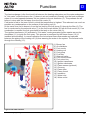
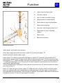
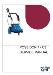
The heat exchanger is the functional link between the heating subsystem and the water subsystem.
In "Hot water" mode the burner fan (1) draws in air and conducts it laterally into the heat exchanger
where it is routed upwards between the two jackets to the air distributor (2). This preheats the air
before it mixes with the fuel spray from the fuel nozzle (3).
Cold water is fed to the inner circuit in which the temperature is highest. This reduces in as much as
possible any condensation on the surface of the heating coil (4).
At the same time fuel is drawn in from the fuel tank by the fuel pump (5) through the filter (6). The
fuel is conducted by the solenoid valve (7) to the fuel nozzle holder (8) with the fuel nozzle (3). If no
combustion is needed, the fuel goes back to the tank on the return line (9).
The ignition transformer (10) activated in "Hot water" mode generates ignition sparks across the
electrodes (11) to ignite the fuel spray. This process is monitored by the flame sensor (12) (if
installed and activated). In normal operation the hot exhaust flows downwards and upwards
between the piping of the heating coil (4) thus warming the water in the system. The exhaust exits
through the chimney (13).
1.) Burner fan
2.) Air distributor
3.) Fuel nozzle
4.) Heating coil
5.) Fuel pump
6.) Fuel filter
7.) Solenoid valve
8.) Fuel nozzle holder
9.) Fuel return line
10.) Ignition transformer
11.) Ignition electrodes
12.) Flame sensor (optional)
13.) Chimney
14.) Flame tube
15.) Flame funnel
16.) Insulation
17.) Water inlet
18.) Water outlet
Fig.D.2: Hot water function
NEPTUNE 4 FA_EN_Ver.2.0_ 22/11
25
Function
D
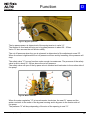
Fig.D.3: Sensors & actors
Sensors:
B1: Temperature sensor in the outlet from the boiler. Controls the combustion (Y1 on/off) according
to setting.
B2: Flow switch senses the flow out of the pump into the boiler and controls solenoid Y1 on/off.
B3: Safety thermal switch placed in the exhaust of the machine, if temperature > 270°C/ 518°F will
switch off, if the burner keeps burning without water flow through the boiler. The safety thermal
switch must be reset manually in the electrical box.
B4: Flow switch controls the motor start/stop. When pressure is higher than working pressure the
switch will open and the motor stops.
B6: Oil level-sensor stops the machine if the pump is low on oil. Activates red light on panel.
B7: Flame-sensor detects light from the flame. If the flame is not detected when it should be there,
the machine will be stopped.
B8: Level switch Anti-Stone liquid. If low, yellow light will light up.
B9: Level switch fuel (stops the fuel valve) when low on fuel and yellow light appears on the panel.
MT: Temperature switch stops the motor if the temperature in the windings is >160°C/ 320°F.
Automatic reset.
Actors:
Y1 Solenoid opens/closes the fuel for the burner.
T2: Ignition transformer is on when burner fan is running.
The machine is supplied with main power which is transformed into 8V AC to supply the microprocessor and sensors and 24VAC to supply the actors (contactor, relay, solenoid valve).
To run the machine on hot water the following must be ok: on the front panel S1 and the temperature setting on hot and the spray handle open. If all the sensors are closed and ok K1 will start the motor and K2 the ignition and fan. Y1 will open and let in oil to the combustion chamber. If the flow
stops B2 will open and the 24V supply to the solenoid Y1 will be interrupted and the combustion will
stop.
NEPTUNE 4 FA_EN_Ver.2.0_ 22/11
26
Function
C
A
D
D
H
B
E
G
F
J
I
Fig.D.4: Motor/pump
A:
Stator.
E:
Suction valve.
B:
Rotor.
F:
Pressure valve.
C:
Wobble disc.
G:
BY-pass housing
D:
Ceramic piston.
H:
Water regulation valve
The three ceramic pistons ”D” are driven by a wobble disc ”C”, the mission of which is to transform
the rotating power from the rotor ”B” into the reciprocating pumping pistons ”D”. The angle of the
wobble disc ”C” decides the volume of water which is sucked through the suction valves ”E” and
pressed out through the pressure valves ”F”.
The inlet ”I” and the outlet ”J” are connected directly to the By-pass valve ”G”.
The water volume can be adjusted by the regulation valve ”H”.
NEPTUNE 4 FA_EN_Ver.2.0_ 22/11
27
Function
D
G
F
H
E
D
I
J
K
C
B
A
Fig.D.5: Working pressure
Machine is started and the gun ”J” with correct lance/nozzle is open Machine runs in working pressure ”K”:
The water is pressed from the pump outlet ”A” into the by-pass housing ”C”.
The water runs through the bottom of by-pass housing ”C” and directely to the outlet ”I”.
Due to the water pressure the by-pass piston ”B” is pressed up and the seat ”E” is closed.
G
F
E
D
H
I
J
K
C
B
A
Fig.D.6: By-pass pressure
Machine is started and the gun is closed - By-pass pressure:
When the gun ”J” closes, the pressure inside the by-pass housing equalizes and the by-pass piston
”B” is pressed down by the tension of it’s spring. The seat ”E” in the top of by-pass piston opens.
The water runs from the pump outlet ”A” into the by-pass housing ”C”. Due to the closed gun ”J” and
the opening in the by-pass seat ”E”, the water runs back into the suction side of the pump through
the valve ”D”.
NEPTUNE 4 FA_EN_Ver.2.0_ 22/11
28
Function
D
C
B
A
Fig.D.7: By-pass pressure
The by-pass pressure is determined of the spring tension in valve ”A”.
The tension is fixed and will bring out a by-pass pressure in about 30 - 35 bar.
Valve ”A” also secures the self suction ability.
The cut off pressure when the gun is released, is determined of the adjustment screw ”B”.
When the screw is tightened the cut off pressure will rise and by loosening it the pressure will
drop.
The safety valve ”C” has no function under normal circumstances. The pressure of the safety
valve is set to about 25 - 30 bar above the cut off pressure.
The safety valve will open if the by-pass valve is stocked and lead water to the suction side of
the pump.
G
F
E
D
H
I
K
C
B
A
Fig.D.8: Water reduction
When the water regulation ”G” is turned counter clock wise, the seat ”H” opens and the
water runs both to the outlet of the by-pass housing and in by-pass to the suction side of
the pump.
The pressure ”K” will drop depending of the size of the opening in seat ”H”.
NEPTUNE 4 FA_EN_Ver.2.0_ 22/11
29
Function
D
G
E
I
J
F
D
A:
Hose connection/valve seat.
B:
Non return valves.
C:
Inlet for water from water supply.
D:
Magnet piston for reed switch E
E:
Reed switch for start of motor/pump.
F:
Water inlet from pump.
G:
Non return valve/magnet piston for H
H:
Reed switch for start of heating
system.
I:
Water outlet.
J:
Back flow restriction.
H
A
B
C
Fig.D.9: Flow control
Water supply connected to the machine:
Water from supply passes the non-return valves ”B” and lift up the piston ”D”.
Machine started in cold/hot water mode:
When piston ”D” is lifted up by the flow, the magnet in piston ”D” closes the reed contact NO ”E”
which gives a signal to the PC board, which starts up the motor/pump unit. The flow from the pump
lifts up piston ”G”. To secure the flow is all right, the magnet in piston ”G” closes the reed contact NC
”H” which gives the signal to the PC board. In hot water mode this signal controls the fuel solenoid
valve and the anti scale pump.
The fuel solenoid valve and the anti scale pump will activate when the PC board receives the signal
from reed contact ”H”.
Piston ”G”: When the gun is closed, piston ”G” closes the inlet of the flow control. Inside the piston
there is a retaining valve which opens when the outlet pressure in the flow control is more than10
bar higher than the inlet pressure, when the gun is released. This pressure differens will improve the
movement of piston ”G” when the gun again is activated.
NEPTUNE 4 FA_EN_Ver.2.0_ 22/11
30
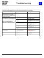
Troubleshooting
Indication lights
Cause
E
Remedy
Constant light
The appliance is ready for operation
When switching on, all the LEDs light up
once before the motor is switched on.
Flashing light
Flow sensor fault
Water tap closed or water shortage
Contact Nilfisk-ALTO Service
Cold water operation possible
Required volume flow and pressure
Detergent tank empty
Top up detergent tank or set detergent metering to
“OFF“
Pressure regulation on The safety
Turn the twist grip on safety control block or Vacontrol block or VarioPress-lance set to
rioPress lance1) to higher water volume
low Water volume
Contact Nilfisk-ALTO Service
Machine scaled
Not ON
Plug not connected to the electrical Put the plug into the electrical socket.
plug socket
Check fuse
Constant light
Fuel shortage
Top up fuel
Cold water operation is possible
Flashing light
Top up Nilfisk-ALTO AntiStone
Nifisk-ALTO AntiStone shortage
Constant light
Service interval has expired
Contact Nilfisk-ALTO Service
Flashing light
Service interval due in 20 hours
Contact Nilfisk-ALTO Service
Constant light
Pump oil low
Top up pump oil
Flashing light (simultaneously)
Leakage or inadmissible operating con- After three times of short-time operation the manchidition by short-time operation
ne switches off. Reset: Turn main switch to position
“OFF“, then start again. Keep spray gun pressed for
longer than 3 seconds. If a leak occurs causing the
machine to start and stop briefly 3 times, then the
machine will switch off.
Spray gun leaking
Check Spray gun
High pressure hose, coupling or line
system leaking
Replace high pressure hose, retighten screw fittings
Detergent tank empty
Top up detergent tank or set detergent metering to
“OFF“
Water inlet filter dirty
Clean filter
High-pressure pump drawing in air
Repair leaks
NEPTUNE 4 FA_EN_Ver.2.0_ 22/11
31
Troubleshooting
Indication lights
Cause
E
Remedy
Flashing light (alternately)
Motor overheated
Turn main switch in position “OFF“, let the machine cool down
Remove/disconnect extension cable
Possible phase failure; have electrical connection
checked
Machine overheated
Contact Nilfisk-ALTO Service
Flashing light
Flame sensor sooted
Ignition or fuel system failure
Fault
Pressure too low
Machine is running with
pulsating pressure and
makes knocking noise
No detergents drawn in
Burner soots
Clean flame sensor
Contact Nilfisk-ALTO Service
Cold water operation possible
Cause
Remedy
High pressure nozzle worn out
Pressure regulation set to low pressure or
VarioPress-lance set to low water volume.
Pump has drawn in air as the detergent
tank is empty.
Detergent tank empty
Dirt in detergent tank
Suction valve at cleaning agent inlet
soiled
Fuel contamination
Burner sooted or adjustment incorrect
NEPTUNE 4 FA_EN_Ver.2.0_ 22/11
Replace nozzle
Turn the twist grip on safety control block
clockwise (+) or set VarioPress-lance to
higher water volume.
Close detergent valve. Remove lance from
gun. Operate spray gun and let machine run
until air in pump is gone and the machine is
running normally/calm again.
Top up detergent tank
Clean detergent tank
Remove suction valve and clean or replace
Contact Alto Service
Contact Alto Service
32
Troubleshooting
E
Boiler performance
The symptom is reduced performance of the pump effect or the boiler effect. The symptom of reduced boiler effect is a
lower water outlet temperature than the set value. The possible causes for this are as follows:
Fault
Cause
Remedy
Scale deposits in boiler tube:
The hardness of the water
Scale formation acts as insulation and
reduces heat transfer to the water.
The result is raised flue gastemperature
= increased flue gas loss.
Descale boiler tube.
Sooted boiler tube:
Air deficiency.
Soot has the same effect as scale deposits, i.e. that they are both insulating
Bad oil/air mixture.
against the heat transfer to the water
and results in increased flue gas temperature = increased flue gas loss.
Unfinished combustion.
Other symptoms are that the machine
smokes during steady operation.
Check air adjustment and fan attachment to boiler.
Unstable ignition.
Check oil pressure and oil quality.
Replace the oil nozzle. Adjust air
diffuser.
Check bottom insulation, boiler top
gasket between tube and inner
boiler jacket in top cover.
Check burner tube.
Check electrodes. Adjust the air
quantity (less air).
Leaky solenoid valve on pump Check/replace solenoid valve Y1.
Y1.
Low oil pressure
Incorrect adjustment.
Adjust pump pressure
(see page 45).
Filter blocked, defective pump. Replace filter/pump. Empty and
clean tank.
Full water quantity at steam stage
NEPTUNE 4 FA_EN_Ver.2.0_ 22/11
Mechanical defect of by-pass
valve or adjustment.
Check by-pass valve.
33
Service / Repair
F
Observations
Fig.F.01: Data Plate
Fig.F.02: Water filter—Cleaning
Prior to any maintenance, identify the
External. Back left-hand side
Internal. Inside the Electrical Box.
As required clean the water filter.
Unscrew connector for water break tank.
Pull out the filter by use of a nose pliers.
Clean the filter and inspect for damages.
Clean the filter.
Replace if necessary.
Oil maintenance
Fuel filter.
Fig.F.03: Oil extention.
Fig.F.04: Fuel filter.
Check the pump oil quality and quantity.
Check the fuel filter and replace if necessary.
machine version at the data plate.
The data plate is situated in two places at the
machine.
Refill if necessary.
Change the oil at major repairs.
Type of oil, refer to part ”B”.
NEPTUNE 4 FA_EN_Ver.2.0_ 22/11
34
Service / Repair
F
Electrical system - Maintenance
Fig.F.05: Electrical box
Fig.F.06: E box knob disassembly
Caution ! Before any repair on the electrical
Loosen the screw in the bottom of the knob.
Drag the knob out from the shaft.
Note ! When closing the electrical box, leave
system - Pull out the power plug !
Remove the cover by loosing the screws
shown in the red circles.
Caution ! On 1 ~ machines capacitor might
the wiring diagram inside.
still be charged !
Fig.F.07: Electrical box - Exploded view.
Fig.F.08: Electrical box - Back side.
The components in the E-box are shown by
numbers in the wiring diagrams chapter H.
Before connecting devices with voltage
changeover: Check that the pre-selected
voltage on the machine corresponds with the
voltage of the electrical installation.
Otherwise the electrical devices of the
machine can be destroyed.
NEPTUNE 4 FA_EN_Ver.2.0_ 22/11
35
Service / Repair
F
By-pass system
1210558
Fig.F.10: By-pass - valve cone.
By reassembling of the valve cone inside the
water regulation, special tool no 1210558 can
be used.
Fig.F.09: By-pass—water regulation.
By assembling and disassembling of the parts
in the by-pass system be aware of the order of
the components.
Fig.F.11: By-pass - water regulation.
By reassembling of the water regulation knob,
special tool no 1211697 can be used.
NEPTUNE 4 FA_EN_Ver.2.0_ 22/11
36
Service / Repair
F
Valves
Fig.F.12: Valve housing
Fig.F.13: Thrust collar
Dismount the valve housing from the
cylinder block by the three M12 bolts.
Be aware of the o-rings and valve parts.
Be carefull not to damage the surface
inside when dismounting the thrust collar.
Inspect the thrust collar for damages
before mounting.
Puller used in the picture is
Bahco 4521N-F.
Fig.F.14: Valve housing
Fig.F.15: Valve housing
Carefully tip out the sleeves with an
adequate screwdriver and replace them. Be
careful not to scratch the surface.
NEPTUNE 4 FA_EN_Ver.2.0_ 22/11
Knock carefully on the back side of the
valve seat with an 8-10mm mandrel to
demount and pull it out.
Replace with new parts.
37
Service / Repair
F
Valves
Pic. F.16: Suction valves
Pic. F.17: Pressure valves
Overview of the placement of suction valve
parts.
Overview of the placement of pressure
valve parts
Picture of piston guides
Fig.F.18: Pressure valves
Fig.F.19: Pressure valve seat
The pressure valves can easily be taken
out of the cylinder head.
Replace with new parts if necessary.
NEPTUNE 4 FA_EN_Ver.2.0_ 22/11
Take out the pressure valve seats with
an adequate puller.
Replace with new parts if necessary.
Puller used in the picture is Bahco
4521N-00
38
Service / Repair
F
Cylinder block
Fig.F.20: Cylinder block
Fig.F.21: Oil Sleeves
Overview of the placement of the parts in
the cylinder block.
Take out the oil sleeves using an
adequate puller.
Be careful not to damage the surface of
the cylinder block.
Puller used in the picture is Bahco
4521N-F.
Oil seal and piston
Fig.F.22: Valve Kit 3~ - Exploded View
Fig.F.23: Pistons
To make replacement easier moisten the
sleeves with soapy water.
Mount the sleeves using a 19mm box
spanner and a fiber hammer.
NEPTUNE 4 FA_EN_Ver.2.0_ 22/11
Place sleeves, pistons and springs as
shown.
Mount the cylinder block to the D-bearing
cover by the two 6mm mounting screws.
39
Service / Repair
F
Replacement of secondary seals and header ring
Pic.9. Showing the right position of the
header ring. Knob on header ring must
be placed in groove against the centre
of the cylinder head.
Fig.F.24: Header ring
If the header ring is mounted wrongly and not according
to instruction, there is a big risk of damaging the header
ring and parts of it will block pistons and valves in the
pump or get stucked in the non return valve in the unloader.
Fig.F.25: Damaged header ring
NEPTUNE 4 FA_EN_Ver.2.0_ 22/11
40
Service / Repair
F
Wobble disc
Fig.F.26: Pump head
Fig.F.27: D-bearing cover and wobble disc
The cylinder head and the cylinder block
is fastend to the D-bearing cover by two
6mm mounting bolts for the cylinder
block and three 12mm bolts for the
cylinder head.
Overview of the parts inside the Dbearing cover.
Fig.F.28: Wobble disc
Fig.F.29: Wobble disc removal
The center bolt is fixing the wobble disc
to the motor shaft and ensure the rotor to
be kept in the right position in proportion
to the stator.
NEPTUNE 4 FA_EN_Ver.2.0_ 22/11
Demount the wobble disc screwing a
16mm bolt into the threads. Tighten the
bolt against the motorshaft and pull the
wobble disc out.
41
Service / Repair
F
Bearing system
A
B
Fig.F.30: Bearing track removal
Fig.F.31: Bearing system & woble disc
Remove bearing track in D-bearing cover.
Replace the complete wobble disc
system and make sure parts are as
sembled according to instructions Fig.32
& Fig.33 pos. A & B
B
A
Fig.F.32: Bearing track
Fig.F.33: Bearing track
The curved edge (A) of the bearing tracks
must be mounted against the D-bearing
cover and the wobble disc.
NEPTUNE 4 FA_EN_Ver.2.0_ 22/11
The sharpe edge (B) of the bearing track
must be mounted against the bearings
42
Service / Repair
F
D-bearing cover
Fig.F.34: D-bearing cover
Fig.F.35: Oil sleeve
The D-bearing cover is mounted to the
Motor by four 6mm bolts.
When the bearing is damaged, always
replace the complete D-bearing cover.
The oil sleeve in the D-bearing cover can
be demounted carefully using a
screwdriver.
Mount the oil sleeve by using an
adequate box spanner and a fiber
hammer.
Electrical motor
Fig.F.36: Electrical Motor
Fig.F.37: fan
Overview of the motor parts.
NEPTUNE 4 FA_EN_Ver.2.0_ 22/11
The fan can be demounted by taking off
the lock ring and carefully push the fan
with a screwdriver.
43
Service / Repair
Fuel tank.
F
Heating system.
1.
2.
3.
4.
5.
6.
2
3
4
1
Fig.F.38: Fuel tank - Overview.
Fig.F.49. Boiler top
1. Fuel tank.
2. Strainer.
3. Float valve
4. Gasket.
Fig.F.39: Heating system - Overview.
1. Ignition Transformer.
2. Ignition cords.
3. Ignition electrodes
4. Flame sensor.
5. Fuel nozzle.
6. Air distributer.
4mm
5mm
5mm
Fig.F.40: Fuel nozzle.
NEPTUNE 4 FA_EN_Ver.2.0_ 22/11
Fig.F.41: Fuel nozzle.
44
Service / Repair
F
Exhaust temperature sensor.
Fig.F.42: Temperatur sensor.
Fig.F.43: Temperatur relay.
The exhaust temperature sensor is fitted with
If the exhaust temperature reaches 270°C
(518°F) the machine cuts out. The relay placed in the E-box can be reset by pressing the
green button.
2 screws in the exhaust.
Burner Unit.
Fuel solenoid
Fuel pump
Burner motor
Burner housing
Fuel filter
Fan
Fan cover
Fig.F.44: Burner unit.
NEPTUNE 4 FA_EN_Ver.2.0_ 22/11
45
Service / Repair
F
Heat exchanger
Fig.F.45: Dismounting coil
Fig.F.46: Dismounting coil
Remove the outer top cover and mount the
lifting tool over the two coil ends and fix it with
the nuts. Dismount the 4 nuts
"Arrows"and hook up the crane and lift out the
coil.
When landing on the floor press over to the
side or protect the machine by a piece of cardboard.
Attention : Be aware of the fact that the machine can tip over. Keep the coil close to the machine.
A
B
Fig.F.47: Dismounting coil
Fig.F.48: Inspection of coil
Check the flame tube A and B. It is important
that they are solid and whole.
Clean up deposits and change the isolation if
needed.
NEPTUNE 4 FA_EN_Ver.2.0_ 22/11
46
Adjustment / Test
G
Torque specifications
20 Nm
20 Nm
Fig.G.01: Wobble disc
Fig.G.02: Cylinder block
65 Nm
Fig.G.03: Cylinder head
25 Nm
Fig.G.04: Venting valve
10 Nm
By hand
Fig.G.05: By-pass housing
Fig.G.06: Venting valve
40 Nm
Fig.G.07: Outlet fittings
NEPTUNE 4 FA_EN_Ver.2.0_ 22/11
40 Nm
Fig.G.08: Water regulation
47
Adjustment / Test
G
Adjustment of by-pass system.
A
Fig.G.09: Pressure gauge
Fig.G.10: Test tap
Connect test pressure gauge 1206358 to the
machine water outlet.
Machines with hose reel:
Connect extension hose 301001311and test
pressure gauge 1206358 to the machine water
outlet
B
Fig.G.11: Safety valve
Fig.G.12: Pressure bolt
Check the working pressure in data sheets
chapter B.
Turn pressure bolt (B . Fig. G12) 1 to 2 turns
out, to ensure that a too high cut off pressure
will not damage the by-pass valve.
Close the safety valve completely.
Adjust the test tap (A. Fig G.09 & G.10) and
the pressure bolt (B) so it couples 20-30 bars
higher than working pressure, when the pressure gun is closed— CUT OFF PRESSURE.
After the cut off pressure is reached the machine runs in by-pass untill the pressure gun is
opened.
NEPTUNE 4 FA_EN_Ver.2.0_ 22/11
48
Adjustment / Test
G
Fig.G.13: Pressure bolt
Fig.G.14: Safety valve
When adjustment is done, lock the bolt with
the counter nut.
NOTE: If the cut off pressure is adjusted too
high > 60 bar higher than working pressure,
the by-pass valve can be damaged due to fast
and hard movements during the change from
working pressure to by-pass pressure.
Let the machine run 5 bars lower than the cut
off pressure (working + adjustment) and adjust
the safety valve out (Counter clockwise) until it
couples out (go into bypass). Then you turn
the adjusting “screw” a ½ turn back
(Clockwise) and lock it with the counter nut.
Open and close the pressure gun a couple of
times to check the adjustment.
Finalize the adjustment with locking glue/paint
on both the bolt and the safety valve.
NEPTUNE 4 FA_EN_Ver.2.0_ 22/11
49
Adjustment / Test
G
Burner settings.
Note: Higher CO2 concentrations at different barometric pressure, altitude or temperature and poor
quality of the used fuel can lead to faster soot deposition on the heating coil of the heat exchanger.
Preparation
1. Set the fuel pressure.
2. Let the machine run in "Hot water" mode for at least two minutes so that it reaches operating temperature and meaningful results can be measured.
Note: Machines that are primarily used for a brief period should run continuously for about half an
hour in "Hot water" mode before an exhaust measurement.
Measurement
3. Determine the soot rating with a soot pump and soot rating reference scale. The figure should not
exceed "1". Otherwise, open the air flap a little and repeat the measurement. Repeat the procedure
until the specified value is obtained.
4. Then the CO2 content in the exhaust, the intake and exhaust temperature are determined. This
can be done with conventional meters or with an electronic meter like the TESTO 325, which measures and displays all relevant data.
If the measured value is too low, close the air flap a little and check the soot rating and Co2 content
again.
Repeat all settings until all specified values are obtained.
5. Finally seal the set screw (arrow A) of the air flap with varnish.
Fig.G.15: Fuel pressure setting.
Fig.G.16: Air flap.
Mount pressure gauge on the fuel pump.
Adjust the fuel pressure according to the values in Technical data chapter A.
The air flap on the side of the burner fan is
adjusted by a self-locking spindle on a set
screw. Turning clockwise increases the air intake, turning counterclockwise reduces it.
NEPTUNE 4 FA_EN_Ver.2.0_ 22/11
50
Adjustment / Test
G
Burner settings.
Fig.G.17: Soot raiting
Fig.G.18: Burner measurements.
Determine the soot rating with a soot pump (1)
and soot rating reference scale. The figure
should not exceed "1". Otherwise, open the air
flap (Fig.G.07) a little and repeat the measurement. Repeat the procedure until the specified
value is obtained.
The CO2 content in the exhaust, the intake
and exhaust temperature are determined. This
can be done with conventional meters or, as in
Fig. G.08, with an electronic meter like the
TESTO 327 (4), which measures and displays
all relevant data.
If the measured value is too low, close the air
flap (Fig.G.06) a little and check the soot rating
and Co2 content again.
NEPTUNE 4 FA_EN_Ver.2.0_ 22/11
51
Adjustment / Test
G
Electronic settings.
1)
BR1
2)
BR2
3)
X5
4)
Fuel LED
5)
Anti Scale LED
6)
Service LED
7)
Pump oil LED
8)
Operation LED
9)
Service jumper
301001873
Fig.G.20: Electronic adjustment.
Setting possibilities:
BR1 (1): this can be used to eliminate the pump bypass time of 20 seconds.
- With jumper: bypass time active
- Without jumper:
bypass time eliminated
BR2 (2): this can be used to activate the optional flame probe.
- Jumper on 1/2:
flame probe inactive
- Jumper on 2/3:
flame probe active
X5 (3): the data logger is connected here for readout of operating data. X5 is also important for setting the service interval.
Service interval settings:
Switch off the machine with S1. Place a wire jumper (9) between pins 3 and 5 on X5.
Switch on the machine ("Cold water" mode). By temperature setting it is now possible
to set a new service interval, read from the status display LEDs (4-8): beginning with
the "Fuel" LED (4), each LED stands for 100 h, producing a setting range of 100 to 500
h in 100 h increments. If the setting is not altered for 3 s, the value is assumed, indicated by flashing of the set LEDs. The machine must then be switched off by S1, and the
wire jumper removed from X5. The default ex works is 200 h.
NEPTUNE 4 FA_EN_Ver.2.0_ 22/11
52
Wiring diagrams
NEPTUNE 4 FA_EN_Ver.2.0_ 22/11
H
53
Wiring diagrams
NEPTUNE 4 FA_EN_Ver.2.0_ 22/11
H
54
Wiring diagrams
NEPTUNE 4 FA_EN_Ver.2.0_ 22/11
H
55
Wiring diagrams
NEPTUNE 4 FA_EN_Ver.2.0_ 22/11
H
56
Wiring diagrams
NEPTUNE 4 FA_EN_Ver.2.0_ 22/11
H
57
Wiring diagrams
NEPTUNE 4 FA_EN_Ver.2.0_ 22/11
H
58
Wiring diagrams
NEPTUNE 4 FA_EN_Ver.2.0_ 22/11
H
59
Wiring diagrams
NEPTUNE 4 FA_EN_Ver.2.0_ 22/11
H
60
Wiring diagrams
NEPTUNE 4 FA_EN_Ver.2.0_ 22/11
H
61
Notes
NEPTUNE 4 FA_EN_Ver.2.0_ 22/11
62