1
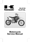
KLX110
Motorcycle
Service Manual
Quick Reference Guide
This quick reference guide will assist
you in locating a desired topic or procedure.
•Bend the pages back to match the
black tab of the desired chapter number with the black tab on the edge at
each table of contents page.
•Refer to the sectional table of contents
for the exact pages to locate the specific topic required.
General Information
1 j
Periodic Maintenance
2 j
Fuel System
3 j
Engine Top End
4 j
Clutch
5 j
Engine Lubrication System
6 j
Engine Removal/Installation
7 j
Crankshaft / Transmission
8 j
Wheels/Tires
9 j
Final Drive
10 j
Brakes
11 j
Suspension
12 j
Steering
13 j
Electrical System
14 j
Troubleshooting
15 j
KLX110
Motorcycle
Service Manual
All rights reserved. No parts of this publication may be reproduced, stored in a retrieval system, or
transmitted in any form or by any means, electronic mechanical photocopying, recording or otherwise,
without the prior written permission of Quality Assurance Division/Consumer Products & Machinery
Company/Kawasaki Heavy Industries, Ltd., Japan.
No liability can be accepted for any inaccuracies or omissions in this publication, although every possible
care has been taken to make it as complete and accurate as possible.
The right is reserved to make changes at any time without prior notice and without incurring an obligation
to make such changes to products manufactured previously. See your Motorcycle dealer for the latest
information on product improvements incorporated after this publication.
All information contained in this publication is based on the latest product information available at the time
of publication. Illustrations and photographs in this publication are intended for reference use only and may
not depict actual model component parts.
© 2001 Kawasaki Heavy Industries, Ltd.
8th Edition (1): May 16, 2008 (K)
LIST OF ABBREVIATIONS
A
ABDC
AC
ATDC
BBDC
BDC
BTDC
°C
DC
F
°F
ft
g
h
L
ampere(s)
after bottom dead center
alternating current
after top dead center
before bottom dead center
bottom dead center
before top dead center
degree(s) Celsius
direct current
farad(s)
degree(s) Fahrenheit
foot, feet
gram(s)
hour(s)
liter(s)
lb
m
min
N
Pa
PS
psi
r
rpm
TDC
TIR
V
W
Ω
pound(s)
meter(s)
minute(s)
newton(s)
pascal(s)
horsepower
pound(s) per square inch
revolution
revolution(s) per minute
top dead center
total indicator reading
volt(s)
watt(s)
ohm(s)
Read OWNER’S MANUAL before operating.
EMISSION CONTROL INFORMATION
To protect the environment in which we all live, Kawasaki has incorporated crankcase emission
(1) and exhaust emission (2) control systems in compliance with applicable regulations of the
California Air Resources Board.
1. Crankcase Emission Control System
This system eliminates the release of cranckcase vapors into the atmosphere. Instead, the
vapors are routed through an oil separator to the inlet side of the engine. While the engine is
operating, the vapors are drawn into combustion chamber, where they are burned along with the
fuel and air supplied by the carburetor.
2. Exhaust Emission Control System
This system reduces the amount of pollutants discharged into the atmosphere by the exhaust
of this motorcycle. The fuel and ignition systems of this motorcycle have been carefully designed
and constructed to ensure an efficient engine with low exhaust pollutant levels.
TAMPERING WITH EMISSION CONTROL SYSTEM PROHIBITED
California State law prohibits the following acts or the causing thereof: (1) the removal or
rendering inoperative by any person other than for purposes of maintenance, repair, or replacement, of any device or element of design incorporated into any new motorcycle for the purposes
of emission control prior to its sale or delivery to the ultimate purchaser or while it is in use, or (2)
the use of the motorcycle after such device or element of design has been removed or rendered
inoperative by any person.
Among those acts presumed to constitute tampering are the acts listed below:
Do not tamper with the original emission related parts:
Carburetor and internal pars
Spark plug
Magneto ignition system
Air cleaner element
•
•
•
•
TAMPERING WITH NOISE CONTROL SYSTEM PROHIBITED
Federal law prohibits the following acts or the causing thereof: (1) The removal or rendering
inoperative by any person other than for purposes of maintenance, repair, or replacement, of any
device or element of design incorporated into any new vehicle for the purpose of noise control
prior to its sale or delivery to the ultimate purchaser or while it is in use, or (2) the use of the
vehicle after such device or element of design has been removed or rendered inoperative by
any person.
Among those acts presumed to constitute tampering are the acts listed below:
Replacement of the original exhaust system or muffler with a component not in compliance
with Federal regulations.
Removal of the muffler(s) or any internal portion of the muffler(s).
Removal of the air box or air box cover.
Modifications to the muffler(s) or air inlet system by cutting, drilling, or other means if such
modifications result in increased noise levels.
•
•
•
•
Foreword
This manual is designed primarily for use by
trained mechanics in a properly equipped shop.
However, it contains enough detail and basic information to make it useful to the owner who desires to perform his own basic maintenance and
repair work. A basic knowledge of mechanics,
the proper use of tools, and workshop procedures must be understood in order to carry out
maintenance and repair satisfactorily. Whenever the owner has insufficient experience or
doubts his ability to do the work, all adjustments, maintenance, and repair should be carried out only by qualified mechanics.
In order to perform the work efficiently and
to avoid costly mistakes, read the text, thoroughly familiarize yourself with the procedures
before starting work, and then do the work carefully in a clean area. Whenever special tools or
equipment are specified, do not use makeshift
tools or equipment. Precision measurements
can only be made if the proper instruments are
used, and the use of substitute tools may adversely affect safe operation.
For the duration of the warranty period,
we recommend that all repairs and scheduled
maintenance be performed in accordance with
this service manual. Any owner maintenance or
repair procedure not performed in accordance
with this manual may void the warranty.
To get the longest life out of your vehicle:
Follow the Periodic Maintenance Chart in the
Service Manual.
Be alert for problems and non-scheduled
maintenance.
Use proper tools and genuine Kawasaki Motorcycle parts. Special tools, gauges, and
testers that are necessary when servicing
Kawasaki motorcycles are introduced by the
Service Manual. Genuine parts provided as
spare parts are listed in the Parts Catalog.
Follow the procedures in this manual carefully. Don’t take shortcuts.
Remember to keep complete records of maintenance and repair with dates and any new
parts installed.
•
•
•
•
•
How to Use This Manual
In this manual, the product is divided into
its major systems and these systems make up
the manual’s chapters. The Quick Reference
Guide shows you all of the product’s system
and assists in locating their chapters. Each
chapter in turn has its own comprehensive Table of Contents.
For example, if you want ignition coil information, use the Quick Reference Guide to locate
the Electrical System chapter. Then, use the
Table of Contents on the first page of the chapter to find the Ignition Coil section.
Whenever you see these WARNING and
CAUTION symbols, heed their instructions!
Always follow safe operating and maintenance
practices.
WARNING
This warning symbol identifies special
instructions or procedures which, if not
correctly followed, could result in personal injury or loss of life.
CAUTION
This caution symbol identifies special
instructions or procedures which, if not
strictly observed, could result in damage to or destruction of equipment.
This manual contains four more symbols (in
addition to WARNING and CAUTION) which will
help you distinguish different types of information.
NOTE
○This note symbol indicates points of par-
ticular interest for more efficient and convenient operation.
a procedural step or work to be
• Indicates
done.
○Indicates a procedural sub-step or how to do
the work of the procedural step it follows. It
also precedes the text of a NOTE.
Indicates a conditional step or what action to
take based on the results of the test or inspection in the procedural step or sub-step it follows.
In most chapters an exploded view illustration
of the system components follows the Table of
Contents. In these illustrations you will find the
instructions indicating which parts require specified tightening torque, oil, grease or a locking
agent during assembly.
GENERAL INFORMATION 1-1
General Information
1
Table of Contents
Before Servicing .....................................................................................................................
Model Identification.................................................................................................................
General Specifications............................................................................................................
Torque and Locking Agent......................................................................................................
Special Tools and Sealants ....................................................................................................
Cable, Wire and Hose Routing ...............................................................................................
Unit Conversion Table ............................................................................................................
1-2
1-5
1-6
1-8
1-11
1-17
1-22
1-2 GENERAL INFORMATION
Before Servicing
Before starting to service a motorcycle, careful reading of the applicable section is recommended to
eliminate unnecessary work. Photographs, diagrams, notes, cautions, warnings, and detailed descriptions have been included wherever necessary. Nevertheless, even a detailed account has limitations,
a certain amount of basic knowledge is also required for successful work.
Especially note the following:
(1) Dirt
Before removal and disassembly, clean the motorcycle. Any dirt entering the engine will shorten
the life of the motorcycle. For the same reason, before installing a new part, clean off any dust or
metal filings.
(2) Battery Ground
Disconnect the ground (–) wire from the battery before performing any disassembly operations
on the motorcycle. This prevents the engine from accidentally turning over while work is being
carried out, sparks from being generated while disconnecting the cables from electrical parts, as
well as damage to the electrical parts themselves. For reinstallation, first connect the positive
cable to the positive (+) terminal of the battery
(3) Installation, Assembly
Generally, installation or assembly is the reverse of removal or disassembly. However, if installation or assembly sequence is given in this Service Manual, follow it. Note parts locations and
cable, wire, and hose routing during removal or disassembly so they can be installed or assembled in the same way. It is preferable to mark and record the locations and routing whenever
possible.
(4) Tightening Sequence
When installing bolts, nuts, or screws for which a tightening sequence is given in this Service
Manual, make sure to follow the sequence. When installing a part with several bolts, nuts, or
screws, start them all in their holes and tighten them to a snug fit, thus ensuring that the part has
been installed in its proper location. Then, tighten them to the specified torque in the tightening
sequence and method indicated. If tightening sequence instructions are not given, tighten them
evenly in a cross pattern. Conversely, to remove a part, first loosen all the bolts, nuts, or screws
that are retaining the part a 1/4-turn before removing them.
(5) Torque
When torque values are given in this Service Manual, use them. Either too little or too much
torque may lead to serious damage. Use a good quality, reliable torque wrench.
(6) Force
Common sense should dictate how much force is necessary in assembly and disassembly. If
a part seems especially difficult to remove or install, stop and examine what may be causing the
problem. Whenever tapping is necessary, tap lightly using a wooden or plastic-faced mallet. Use
an impact driver for screws (particularly for the removing screws held by non-permanent locking
agent) in order to avoid damaging the screw heads.
(7) Edges
Watch for sharp edges, as they could cause injury through careless handling, especially during
major engine disassembly and assembly. Use a clean piece of thick cloth when lifting the engine
or turning it over.
(8) High-Flash Point Solvent
A high-flash point solvent is recommended to reduce fire danger. A commercial solvent commonly available in North America is standard solvent (generic name). Always follow manufacturer
and container directions regarding the use of any solvent.
(9) Gasket, O-ring
Replace a gasket or an O-ring with a new part when disassembling. Remove any foreign matter
from the mating surface of the gasket or O-ring to ensure a perfectly smooth surface to prevent
oil or compression leaks.
(10)Liquid Gasket, Locking Agent
Clean and prepare surfaces where liquid gasket or non-permanent locking agent will be used.
Apply them sparingly. Excessive amount may block engine oil passages and cause serious damage.
GENERAL INFORMATION 1-3
Before Servicing
(11) Press
When using a press or driver to install a part such as a wheel bearing, apply a small amount of
oil to the area where the two parts come in contact to ensure a smooth fit.
(12)Ball Bearing and Needle Bearing
Do not remove a ball bearing or a needle bearing unless it is absolutely necessary. Replace any
ball or needle bearings that were removed with new ones. Install bearings with the manufacturer
and size marks facing out, applying pressure evenly with a suitable driver. Apply force only to the
end of the race that contacts the press fit portion, and press it evenly over the base component.
(13)Oil Seal and Grease Seal
Replace any oil or grease seals that were removed with new ones, as removal generally damages seals. Oil or grease seals should be pressed into place using a suitable driver, applying a
force uniformly to the end of seal until the face of the seal is even with the end of the hole, unless
instructed otherwise. When pressing in an oil or grease seal which has manufacturer’s marks,
press it in with the marks facing out.
(14)Circlip, Retaining Ring, and Cotter Pin
When installing circlips and retaining rings, take care to compress or expand them only enough
to install them and no more. Install the circlip with its chamfered side facing load side as well.
Replace any circlips, retaining rings, and cotter pins that were removed with new ones, as removal weakens and deforms them. If old ones are reused, they could become detached while
the motorcycle is driven, leading to a major problem.
(15)Lubrication
Engine wear is generally at its maximum while the engine is warming up and before all the sliding
surfaces have an adequate lubricative film. During assembly, make sure to apply oil to any sliding
surface or bearing that has been cleaned. Old grease or dirty oil could have lost its lubricative
quality and may contain foreign particles that act as abrasives; therefore, make sure to wipe it off
and apply fresh grease or oil. Some oils and greases in particular should be used only in certain
applications and may be harmful if used in an application for which they are not intended.
(16)Direction of Engine Rotation
To rotate the crankshaft manually, make sure to do so in the direction of positive rotation. Positive rotation is counterclockwise as viewed from the left side of the engine. To carry out proper
adjustment, it is furthermore necessary to rotate the engine in the direction of positive rotation as
well.
(17)Replacement Parts
When there is a replacement instruction, replace these parts with new ones every time they are
removed.
Replacement parts will be damaged or lose their original function once they are removed. Therefore, always replace these parts with new ones every time they are removed. Although the previously mentioned gasket, O-ring, ball bearing, needle bearing, grease seal, oil seal, circlip, and
cotter pin have not been so designated in their respective text, they are replacement parts.
(18)Electrical Leads
All the electrical leads are either one-color or two-color. A two-color lead is identified first by
the primary color and then the stripe color. For example, a yellow lead with thin red stripes is
referred to as a “yellow/red” lead; it would be a “red/yellow” lead if the colors were reversed.
Unless instructed otherwise, electrical leads must be connected to leads of the same color.
Two-Color Electrical
1-4 GENERAL INFORMATION
Before Servicing
(19)Inspection
When parts have been disassembled, visually inspect these parts for the following conditions
or other damage. If there is any doubt as to the condition of them, replace them with new ones.
Abrasion
Bent
Color change
Crack
Dent
Deterioration
Hardening
Scratch
Seizure
Warp
Wear
(20)Specifications
Specification terms are defined as follows:
“Standards” show dimensions or performances which brand-new parts or systems have.
“Service Limits” indicate the usable limits. If the measurement shows excessive wear or deteriorated performance, replace the damaged parts.
GENERAL INFORMATION 1-5
Model Identification
KLX110-A1 Left Side View
KLX110-A1 Right Side View
1-6 GENERAL INFORMATION
General Specifications
KLX110-A1 ∼
Items
Dimensions
Overall Length
Overall Width
Overall Height
Wheelbase
Road Clearance
Seat Height
Dry Mass
KLX110-A1 ∼ A8F
Curb Mass:
KLX110A9F ∼
Front
Rear
Fuel Tank Capacity
Performance
Minimum Turning Radius
Engine
Type
Cooling System
Bore and Stroke
Displacement
Compression Ratio
Carburetion System
Starting System
Ignition System
Ignition Timing
Spark Plug
Valve Timing:
Inlet:
Open
Close
Duration
Exhaust:
Open
Close
Duration
Lubrication System
Engine Oil:
Grade
Viscosity
Capacity
1 555 mm (61.2 in.)
660 mm (26.0 in.)
955 mm (37.6 in.)
1 065 mm (41.9 in.)
190 mm (7.5 in.)
650 mm (25.6 in.)
64 kg (628 N, 141 lb)
64 kg (628 N, 141 lb)
31 kg (304 N, 68 lb)
37 kg (363 N, 82 lb)
3.8 L (1.0 US gal)
1.6 m (5.2 ft)
4-stroke, SOHC, single cylinder
Air-cooled
53.0 × 50.6 mm (2.09 × 1.99 in.)
111 cm³ (6.77 cu in.)
9.5 : 1
Carburetor, KEIHIN PB18
Kick
Magneto CDI
From 10° BTDC @1 300 r/min (rpm) to 31°
BTDC @4 000 r/min (rpm)
NGK CR6HSA
0° BTDC
80° ABDC
260°
35° BBDC
45° ATDC
260°
Forced lubrication (wet sump)
API SE, SF or SG
API SH or SJ with JASO MA, MA1 or MA2 (KLX110-A1 ∼ A6F)
API SH, SJ or SL with JASO MA, MA1 or MA2 (KLX110A7F ∼)
SAE 10W-40
1.1 L (1.2 US gt): (when engine is completely dry)
GENERAL INFORMATION 1-7
General Specifications
KLX110-A1 ∼
Items
Drive Train
Primary Reduction System:
Type
Reduction Ratio
Clutch Type
Transmission:
Type
Gear Ratios:
1st
2nd
3rd
Final Drive System:
Type
Reduction Ratio
Overall Drive Ratio
Frame
Type
Caster (Rake Angle)
Trail
Front Tire:
Type
Size
Rear Tire:
Type
Size
Rim Size:
Front
Rear
Front Suspension:
Type
Wheel Travel
Rear Suspension:
Type
Wheel Travel
Brake Type:
Front
Rear
Gear, centrifugal
3.048 (64/21) (KLX110-A1)
3.409 (75/22) (KLX110-A2 ∼)
Centrifugal & wet, multi disc
3-speed, constant mesh, return shift
3.273
3.000
1.938
1.350
(36/11) (KLX110-A1)
(36/12) (KLX110-A2 ∼)
(31/16)
(27/20)
Chain drive
2.642 (37/14) (KLX110-A1)
2.357 (33/14) (KLX110-A2 ∼)
10.873 @Top gear (KLX110-A1)
10.848 @Top gear (KLX110-A2 ∼)
Backbone
25.5°
54 mm (2.1 in.)
C803
2.50 - 14 4PR
2.50 - 14 M/C 4PR (KLX110-A2 ∼)
C803
3.00 - 12 4PR
3.00 - 12 M/C 4PR (KLX110-A2 ∼)
14 × 1.40
12 × 1.60
Telescopic fork
110 mm (4.3 in.)
Swingarm
107 mm (4.2 in.)
Drum
Drum
Specifications are subject to change without notice, and may not apply to every country.
1-8 GENERAL INFORMATION
Torque and Locking Agent
The following tables lists the tightening torque for the major fasteners requiring use of a
non-permanent locking agent or liquid gasket.
Letters used in the “Remarks” column mean:
L: Apply a non-permanent locking agent to the threads.
S: Tighten the fasteners following the specified sequence.
Fastener
Fuel System
Fuel Tap Bolts (KLX110-A3 ∼)
Engine Top End
Rocker Arm Shaft Stopper Screws
Valve Adjusting Screw Locknuts
Camshaft Sprocket Bolt
Cylinder Head Nuts
Cylinder Head Bolts
Spark Plug
Chain Tensioner Mounting Bolts
Tensioner Cap Bolt
Camshaft Sprocket Cover Bolts
Camshaft Chain Guide Bolt
Camshaft Chain Holder Screws
Valve Adjusting Cap Bolts
Spark Arrester Mounting Bolts
Clutch
Clutch Cover Screws (KLX110-A1 ∼ A7F)
Clutch Cover Bolts (KLX110A8F ∼)
Clutch Cover Plate Screws
Clutch Hub Nut (Primary)
Clutch Hub Nut (Secondary)
Clutch Spring Bolts (KLX110-A1 ∼ A2)
Clutch Spring Bolts (KLX110-A3 ∼)
Clutch Adjusting Screw Locknut
Shift Drum Position Plate Screw
Shift Drum Positioning Lever Pivot Bolt
Kick Guide Screw
Return Spring Pin
Engine Lubrication System
Oil Pipe Banjo Bolts
Oil Pipe Clamp Screw
Oil Pump Mounting Screw
Oil Filter Cap Bolts
Engine Oil Drain Plug
Engine Removal/Installation
Engine Mounting Nuts
Side Stand Mounting Nut
N·m
Torque
kgf·m
ft·lb
4.9
0.5
43 in·lb
5.2
8.8
12
22
12
13
5.2
5.2
5.2
5.2
5.2
5.2
8.8
0.53
0.9
1.2
2.2
1.2
1.3
0.53
0.53
0.53
0.53
0.53
0.53
0.9
46 in·lb
78 in·lb
104 in·lb
16
104 in·lb
113 in·lb
46 in·lb
46 in·lb
46 in·lb
46 in·lb
46 in·lb
46 in·lb
78 in·lb
5.2
8.8
2.9
72
72
3.4
5.0
19
5.2
5.2
5.2
22
0.53
0.9
0.3
7.3
7.3
0.35
0.51
1.9
0.53
0.53
0.53
2.2
46 in·lb
78 in·lb
26 in·lb
53
53
30 in·lb
44 in·lb
14
46 in·lb
46 in·lb
46 in·lb
16
15
5.2
5.2
5.2
29
1.5
0.53
0.53
0.53
3.0
11
46 in·lb
46 in·lb
46 in·lb
21
54
23
5.5
2.3
40
17
Remarks
L
S
L,S
L
S
S
L
GENERAL INFORMATION 1-9
Torque and Locking Agent
Fastener
Crankshaft/Transmission
Crankcase Screws
Bearing Retainer Screw 5 mm
Bearing Retainer Screw 6 mm
Shift Return Spring Pin
Shift Drum Allen Bolt
Magneto Flywheel Nut 10 mm (KLX110-A1)
Magneto Flywheel Nut 12 mm (KLX110-A2 ∼)
Clutch Hub Nut
Wheels/Tires
Spoke Nipples
Front Axle Nut
Rear Axle Nut
Torque Link Nut
Final Drive
Swingarm Pivot Shaft Nut
Rear Sprocket Nuts
Rear Axle Nut
Torque Link Nut
Brakes
Front Axle Nut
Rear Axle Nut
Brake Pedal Bolt
Rear Cam Lever Mounting Bolt
Suspension
Front Fork Clamp Bolts:
Upper
Lower
Front Fork Bottom Allen Bolts
Torque Link Nuts:
Front
Rear
Swingarm Pivot Shaft Nut
Rear Shock Absorber Mounting Nuts:
Upper
Lower
Steering
Front Fork Clamp Bolts:
Upper
Lower
Steering Stem Head Nut
Handlebar Holder Bolts
Steering Stem Locknut
N·m
Torque
kgf·m
ft·lb
5.2
2.9
5.2
22
5.2
42
54
72
0.53
0.3
0.53
2.2
0.53
4.3
5.5
7.3
46 in·lb
26 in·lb
46 in·lb
16
46 in·lb
31
40
53
1.2
44
64
25
0.12
4.5
6.5
2.5
10 in·lb
32
47
18
78
34
64
25
8.0
3.5
6.5
2.5
58
25
47
18
44
64
8.8
7.0
4.5
6.5
0.9
0.7
32
47
78 in·lb
60 in·lb
20
29
20
2.0
3.0
2.0
15
22
15
25
25
78
2.5
2.5
8.0
18
18
58
39
39
4.0
4.0
29
29
20
29
44
25
4.9
2.0
3.0
4.5
2.5
0.5
15
22
32
18
43 in·lb
Remarks
L(1) S
L
L
1-10 GENERAL INFORMATION
Torque and Locking Agent
Fastener
Electrical System
Gear Position Switch Screw
Spark Plug
Magneto Flywheel Nut 10 mm (KLX110-A1)
Magneto Flywheel Nut 12 mm (KLX110-A2 ∼)
Exciter Coil Mounting Screws
Crankshaft Sensor Mounting Screw
Magneto Cover Screws (KLX110-A1 ∼ A7F)
Magneto Cover Bolts (KLX110A8F ∼)
Exciter Coil Plate Screw
Crankshaft Sensor Plate Screw
Magneto Cover Damper
N·m
2.9
13
42
54
5.2
2.9
5.2
8.8
5.2
5.2
2.9
Torque
kgf·m
0.3
1.3
4.3
5.5
0.53
0.3
0.53
0.9
0.53
0.53
0.3
ft·lb
26 in·lb
113 in·lb
31
40
46 in·lb
26 in·lb
46 in·lb
78 in·lb
46 in·lb
46 in·lb
26 in·lb
Remarks
S
S
The table below, relating tightening torque to thread diameter, lists the basic torque for the bolts and
nuts. Use this table for only the bolts and nuts which do not require a specific torque value. All of the
values are for use with dry solvent-cleaned threads.
Basic Torque for General Fasteners
Threads dia.
(mm)
5
6
8
10
12
14
16
18
20
N·m
3.4 ∼ 4.9
5.9 ∼ 7.8
14 ∼ 19
25 ∼ 34
44 ∼ 61
73 ∼ 98
115 ∼ 155
165 ∼ 225
225 ∼ 325
Torque
kgf·m
0.35 ∼ 0.50
0.60 ∼ 0.80
1.4 ∼ 1.9
2.6 ∼ 3.5
4.5 ∼ 6.2
7.4 ∼ 10.0
11.5 ∼ 16.0
17.0 ∼ 23.0
23 ∼ 33
ft·lb
30 ∼ 43 in·lb
52 ∼ 69 in·lb
10.0 ∼ 13.5
19.0 ∼ 25
33 ∼ 45
54 ∼ 72
83 ∼ 115
125 ∼ 165
165 ∼ 240
GENERAL INFORMATION 1-11
Special Tools and Sealants
Oil Pressure Gauge, 5 kgf/cm²:
57001-125
Fork Cylinder Holder Handle:
57001-183
Steering Stem Bearing Driver:
57001-137
Compression Gauge, 20 kgf/cm²:
57001-221
Inside Circlip Pliers:
57001-143
Valve Spring Compressor Assembly:
57001-241
Outside Circlip Pliers:
57001-144
Bearing Puller Adapter:
57001-317
Bearing Puller:
57001-158
Piston Pin Puller Assembly:
57001-910
1-12 GENERAL INFORMATION
Special Tools and Sealants
Fork Cylinder Holder Adapter:
57001-1011
Crankcase Splitting Tool Assembly:
57001-1098
Fuel Level Gauge:
57001-1017
Steering Stem Nut Wrench:
57001-1100
Oil Seal & Bearing Remover:
57001-1058
Valve Seat Cutter, 45° 57001-1114
27.5:
Rim Protector:
57001-1063
Valve Seat Cutter, 32° 57001-1118
25:
Bead Breaker Assembly:
57001-1072
Valve Seat Cutter, 60° 57001-1123
30:
GENERAL INFORMATION 1-13
Special Tools and Sealants
Valve Seat Cutter Holder Bar:
57001-1128
Bearing Puller Stud:
57001-1190
Bearing Driver Set:
57001-1129
Valve Seat Cutter, 45° 57001-1205
22:
Valve Seat Cutter, 32° 57001-1206
22:
Valve Spring Compressor Adapter,
57001-1154
20:
Crankshaft Jig:
57001-1174
Valve Seat Cutter, 67.5° 57001-1207
22:
Oil Pressure Gauge Adapter, M10 × 1.25:
57001-1182
Rotor Puller, M16/M18/M20/M22 × 1.5:
57001-1216
1-14 GENERAL INFORMATION
Special Tools and Sealants
Valve Adjusting Screw Holder:
57001-1217
Bearing Remover Head,
57001-1266
Front Fork Oil Seal Driver:
57001-1219
Fork Oil Level Gauge:
57001-1290
Jack:
57001-1238
Flywheel Holder:
57001-1313
Spark Plug Wrench, Hex 16:
57001-1262
Compression Gauge Adapter, M10 × 1.0:
57001-1317
Bearing Remover Shaft,
57001-1265
Valve Seat Cutter Holder,
57001-1330
9:
10 ×
4.5:
12:
GENERAL INFORMATION 1-15
Special Tools and Sealants
Valve Guide Arbor,
57001-1331
4.5:
Valve Guide Reamer,
57001-1333
4.5:
Clutch Holder 1:
57001-1507
Clutch Holder 2:
57001-1508
Hand Tester:
57001-1394
Oil Pressure Cap:
57001-1651
Peak Voltage Adapter:
57001-1415
Pilot Screw Adjuster
57001-1665
Flywheel Puller, M28 × 1.0:
57001-1471
Kawasaki Bond (Silicone Sealant):
56019-120
1-16 GENERAL INFORMATION
Special Tools and Sealants
Kawasaki Bond(Liquid Gasket - Black):
92104-1003
GENERAL INFORMATION 1-17
Cable, Wire and Hose Routing
Dummy Page
1-18 GENERAL INFORMATION
Cable, Wire and Hose Routing
GENERAL INFORMATION 1-19
Cable, Wire and Hose Routing
1. Throttle Cable
2. Engine Stop Switch Lead
3. Band
4. Handlebar
5. Frame
6. Carburetor
7. Clamp
8. Air Vent Hose
9. Regulator/Rectifier
10. Igniter
11. Crankcase Breather Hose
12. Magneto Leads
13. Gear Position Switch Leads
14. Main Harness
15. Choke Knob
16. Ignition Coil
17. Ground Lead
18. Brake Cable
19. Bend the clamp as shown.
20. Approx. 15 mm (0.59 in.)
21. Connect the connector of magneto lead inside of the crankcase breather hose.
A: KLX110-A3 ∼
1-20 GENERAL INFORMATION
Cable, Wire and Hose Routing
GENERAL INFORMATION 1-21
Cable, Wire and Hose Routing
1. Frame
2. Align the damper center with the frame hole.
3. Apply adhesive to diagonal line portion.
4. Clamp
5. Run the carburetor drain hose into a hole of the engine guard.
6. Ignition Coil Lead
7. Inlet Fuel Hose
8. Crankcase Breather Hose
9. Engine Guard
10. Carburetor Drain Hose
11. Clamp
12. Clutch Cover
13. Cylinder Head
14. Carburetor
15. Choke Cable
16. Throttle Cable
17. Regulator/Rectifier
18. Inlet Fitting
1-22 GENERAL INFORMATION
Unit Conversion Table
Prefixes for Units:
Prefix
mega
kilo
centi
milli
micro
Symbol
M
k
c
m
μ
Units of Length:
×
×
×
×
×
Power
1 000 000
1 000
0.01
0.001
0.000001
Units of Mass:
kg
g
×
×
2.205
0.03527
=
=
lb
oz
gal (US)
gal (imp)
qt (US)
qt (imp)
pint (US)
pint (imp)
oz (US)
oz (imp)
cu in
Units of Volume:
L
×
0.2642
=
L
L
L
L
L
mL
mL
mL
×
×
×
×
×
×
×
×
0.2200
1.057
0.8799
2.113
1.816
0.03381
0.02816
0.06102
=
=
=
=
=
=
=
=
km
m
mm
×
×
×
0.6214
3.281
0.03937
=
=
=
mile
ft
in
=
=
=
=
=
=
kgf·m
ft·lb
in·lb
N·m
ft·lb
in·lb
=
=
=
=
=
=
kgf/cm²
psi
cmHg
kPa
psi
kPa
=
mph
=
=
=
=
PS
HP
kW
HP
Units of Torque:
N·m
N·m
N·m
kgf·m
kgf·m
kgf·m
×
×
×
×
×
×
0.1020
0.7376
8.851
9.807
7.233
86.80
Units of Pressure:
kPa
kPa
kPa
kgf/cm²
kgf/cm²
cmHg
×
×
×
×
×
×
0.01020
0.1450
0.7501
98.07
14.22
1.333
Units of Speed:
km/h
×
0.6214
Units of Force:
N
N
kg
kg
×
×
×
×
0.1020
0.2248
9.807
2.205
Units of Temperature:
=
=
=
=
kg
lb
N
lb
Units of Power:
kW
kW
PS
PS
×
×
×
×
1.360
1.341
0.7355
0.9863
PERIODIC MAINTENANCE 2-1
Periodic Maintenance
2
Table of Contents
Periodic Maintenance Chart ..............
Specifications ....................................
Periodic Maintenance Procedures.....
Fuel System....................................
Fuel Hose and Connections
Inspection..................................
Fuel Tap Inspection......................
Fuel Tap Cleaning ........................
Throttle Grip Free Play Inspection
Throttle Grip Free Play
Adjustment ................................
Idle Speed Inspection ..................
Idle Speed Adjustment.................
Air Cleaner Element Cleaning and
Inspection..................................
Engine Top End ..............................
Valve Clearance Inspection .........
Valve Clearance Adjustment........
Spark Arrester Cleaning...............
Clutch..............................................
Clutch Adjustment........................
Engine Lubrication System .............
Oil Level Inspection......................
Oil Change ...................................
Oil Filter Element Replacement ...
Wheels/Tires...................................
Wheels Inspection........................
Spoke Tightness Inspection .........
Wheel Bearing Inspection ............
Rim Runout Inspection.................
Final Drive.......................................
Chain Slack Inspection ................
Chain Slack Adjustment...............
Chain Wear Inspection.................
Chain Lubrication .........................
2-2
2-3
2-5
2-5
2-5
2-5
2-5
2-6
2-6
2-7
2-7
2-7
2-8
2-8
2-9
2-9
2-10
2-10
2-10
2-11
2-11
2-12
2-12
2-12
2-12
2-13
2-13
2-14
2-14
2-14
2-15
2-16
Sprocket Wear Inspection............
Chain Slipper Wear Inspection ....
Brakes.............................................
Brake Lever, Brake Pedal Free
Play Inspection..........................
Front Brake Lever Free Play
Adjustment ................................
Brake Pedal Free Play
Adjustment ................................
Brake Lining Wear Inspection ......
Cam Lever Angle Adjustment ......
Brake Panel Lubrication...............
Suspension .....................................
Fork Oil Level Adjustment
(Simplify) ...................................
Front Fork Inner Tube Inspection.
Rear Shock Absorber Inspection .
Swingarm Pivot Inspection...........
Swingarm Rubber Bushing
Inspection..................................
Steering ..........................................
Steering Inspection ......................
Steering Adjustment.....................
Steering Stem Bearing
Lubrication.................................
Side Stand ......................................
Side Stand Inspection ..................
Electrical System ............................
Spark Plug Gap............................
Spark Plug Cleaning and
Inspection..................................
General Lubrication ........................
Lubrication ...................................
Nut, Bolt and Fastener Tightness ...
Tightness Inspection ....................
2-16
2-17
2-17
2-17
2-18
2-18
2-18
2-20
2-20
2-21
2-21
2-22
2-22
2-23
2-23
2-24
2-24
2-24
2-25
2-25
2-25
2-25
2-25
2-25
2-26
2-26
2-27
2-27
2-2 PERIODIC MAINTENANCE
Periodic Maintenance Chart
The maintenance must be done in accordance with this chart to keep the motorcycle in good running
condition.
FREQUENCY
OPERATION
Engine oil-change
(e)Spark plug-clean, gap †
Clutch-inspection †
(e)Valve clearance-inspection †
Oil filter element-replace
E (e)Air cleaner element-clean †
(e)Idle speed-inspection †
(e)Throttle grip play-inspection †
Fuel tap-clean
Initial
5 hours
(1
month)
•
•
•
•
•
Spark arrester-clean
Engine sprocket-inspection †
Fuel hose, connections-inspection†
Brake lever/pedal play-inspection †
Brake lining wear-inspection †
Brake cable-inspection †
Drive chain slack-inspection†
Drive chain-lubricate
Drive chain wear-inspection †
Front fork-inspection †
C
•
•
Steering stem bearing-grease
•
•
Rear sprocket-inspection †
General lubrication-perform
Side stand-inspection †
Wheel bearing-inspection †
Swingarm pivots-inspection †
Rear shock absorber-inspection †
C: CHASSIS
E: ENGINE
(e): Emission Related
†: Replace, add, adjust or torque if necessary.
Every ride
•
•
•
•
•
•
•
•
•
•
•
See
Page
2-11
2-25
2-10
2-8
2-12
2-7
2-7
•
•
•
•
•
•
•
•
•
2-20
•
•
2-12
•
•
•
•
•
•
2-15
•
•
•
•
•
•
•
•
•
•
•
2-27
Every ride
Every ride
Every year
Front fork oil-inspection †
Steering play-inspection †
•
Every year
Chain slipper-inspection †
Nuts, bolts, fasteners-inspection†
•
•
•
Every ride
Every ride
Brake camshaft-grease
Spoke tightness and rim runout-inspection †
Every
50 hours
100 hours
(6
(12
months)
months)
•
•
•
•
•
2-6
2-5
2-9
2-16
2-5
2-17
2-18
2-26
2-14
2-16
2-22
2-17
2-21
2-24
2-25
2-16
2-26
2-25
2-13
2-23
2-22
PERIODIC MAINTENANCE 2-3
Specifications
Item
Fuel System
Throttle Grip Free Play
Idle Speed
Air Cleaner Element Oil
Engine Top End
Valve Clearance:
Exhaust
Inlet
Clutch
Clutch Adjusting Screw
Engine Lubrication System
Engine Oil:
Type
Viscosity
Capacity
Level
Tires
Rim Runout (with tire installed):
Axial
Radial
Final Drive
Drive Chain Slack
Drive Chain 20-link Length
Brakes
Brake Lever Free Play
Brake Pedal Free Play
Brake Cam Lever Angle:
Front
Rear
Suspension
Fork Oil Viscosity
Fork Oil Level
(Fully Compressed, Without Spring)
Electrical System
Standard Plug
Spark Plug Gap
Standard
Service Limit
2 ∼ 3 mm (0.08 ∼ 0.12 in.)
1 250 ∼ 1 350 r/min (rpm)
High quality foam air filter oil
– – –
– – –
– – –
0.04 ∼ 0.08 mm (0.0016 ∼ 0.0031 in.)
0.04 ∼ 0.08 mm (0.0016 ∼ 0.0031 in.)
– – –
– – –
1/4 turn out
– – –
API SE, SF or SG
API SH or SJ with JASO MA, MA1 or
MA2 (KLX110-A1 ∼ A6F)
API SH, SJ or SL with JASO MA, MA1
or MA2 (KLX110A7F ∼)
SAE 10W-40
1.1 L (1.2 us qt)
(when engine is completely dry)
1.0 L (1.1 us qt)
(when filter is removed)
0.9 L (1.0 us qt)
(when filter is not removed)
Between upper and lower level lines
– – –
– – –
– – –
– – –
TIR 0.8 mm (0.03 in.) or less
TIR 1.0 mm (0.04 in.) or less
TIR 2 mm (0.08 in.)
TIR 2 mm (0.08 in.)
0 ∼ 5 mm (0 ∼ 0.2 in.)
254.0 ∼ 254.6 mm (10.00 ∼ 10.02 in.)
– – –
259 mm (10.20 in.)
4 ∼ 5 mm (0.16 ∼ 0.20 in.)
20 ∼ 30 mm (0.79 ∼ 1.18 in.)
– – –
– – –
80° ∼ 90°
80° ∼ 90°
– – –
– – –
SHOWA SS-8 or equivalent
– – –
89 ±2 mm (3.5 ±0.08 in.)
– – –
NGK CR6HSA
0.6 ∼ 0.7 mm (0.024 ∼ 0.028 in.)
– – –
– – –
2-4 PERIODIC MAINTENANCE
Specifications
Special Tools - Valve Adjusting Screw Holder: 57001-1217
Jack: 57001-1238
Fork Oil Level Gauge: 57001-1290
Steering Stem Nut Wrench: 57001-1100
PERIODIC MAINTENANCE 2-5
Periodic Maintenance Procedures
Fuel System
Fuel Hose and Connections Inspection
the fuel hose [A] for the following.
• Check
Fuel leakage
•
•
Loose or improperly positioned line clamp [B]
Deteriorated or damaged line
Replace the fuel hose if any fraying, cracks or bulges are
noticed.
When installing, route the hoses according to Cable,
Wire, and Hose Routing section in the General Information chapter.
When installing the fuel hoses, avoid sharp bending, kinking, flattening or twisting, and route the fuel hoses with a
minimum of bending so that the fuel flow will not be obstructed.
Replace the hose if it has been sharply bent or kinked.
Fuel Tap Inspection
the fuel tap (see Fuel System chapter).
• Remove
Check
the
• rioration. fuel tap filter screen [A] for any breaks or deteIf the fuel tap screen have any breaks or is deteriorated, it
may allow dirt to reach the carburetor, causing poor running. Replace the fuel tap.
If the fuel tap leaks, or allows fuel to flow when it is at OFF
position, replace the damaged O-ring [B].
Fuel Tap Cleaning
WARNING
Clean the tap in a well-ventilated area, and take
care that there is no sparks or flame anywhere
near the working area. Because of the danger of
highly flammable liquids, do not use gasoline or
low flash-point solvent to clean the tap.
the fuel tap filter screen in a high-flash point sol• Clean
vent.
high-flash point solvent through the tap in all lever
• Pour
positions.
the tank and tap with compressed air.
• Dry
• Install the tap in the tank.
Torque - Fuel Tap Bolts:
KLX110-A3 ∼
• Install the fuel tank.
4.9 N·m (0.5 kgf·m, 43 in·lb)
2-6 PERIODIC MAINTENANCE
Periodic Maintenance Procedures
Throttle Grip Free Play Inspection
If the throttle grip has excessive free play due to cable
stretch or misadjustment, there will be a delay in throttle response. Also, the throttle valve may not open fully at full
throttle. On the other hand, if the throttle grip has no play,
the throttle will be hard to control, and the idle speed will
be erratic. Check the throttle grip play periodically in accordance with the Periodic Maintenance Chart, and adjust the
play if necessary.
The throttle cable routing is shown in Cable, Harness,
Hose Routing section in the General Information chapter.
Check throttle grip free play [B] by lightly turning the throttle grip [A] back and forth.
If the free play is improper, adjust the throttle cable.
•
Throttle Grip Free Play
Standard:
2 ∼ 3 mm (0.08 ∼ 0.12 in.)
Throttle Grip Free Play Adjustment
the locknut [A] at the upper end of the throttle
• Loosen
cable.
the adjuster [B] until the proper amount of throttle
• Turn
grip free play is obtained.
• Tighten the locknut.
•
•
•
If the throttle grip free play cannot be adjusted with the
adjuster at the upper end of the throttle cable, use the
cable adjuster [A] at the carburetor.
Pull the boot off of the carburetor top. Make the necessary
free play adjustment at the lower cable adjuster, tighten
the locknut [B], and install the boot.
Check if the throttle grip moves smoothly from full open to
close, and the throttle closes quickly and completely in all
steering positions by the return spring. If not, check the
throttle cable routing, grip free play, and cable damage.
Then lubricate the throttle cable.
With the engine idling, turn the handlebar both ways and
check if handlebar movement changes the idling speed.
If so, the throttle cable may be improperly adjusted or
incorrectly routed, or damaged. Be sure to correct any
of these conditions before riding.
WARNING
Operation with an improperly adjusted, incorrectly
routed, or damaged cable could result in an unsafe
riding condition.
PERIODIC MAINTENANCE 2-7
Periodic Maintenance Procedures
Idle Speed Inspection
the engine and warm it up thoroughly.
• Start
Turn
the
• gine. handlebar from side to side while idling the enIf handlebar movement changes the idle speed, the throttle cable may be improperly adjusted or incorrectly routed,
or it may be damaged. Be sure to correct any of these
conditions before riding.
WARNING
Operation with an improperly adjusted, incorrectly
routed, or damaged cable could result in an unsafe
riding condition.
idle speed using a tachometer.
• Check
If the idle speed is out of the specified range, adjust it.
Idle Speed
Standard:
1 250 ∼ 1 350 r/min (rpm)
Idle Speed Adjustment
CAUTION
The pilot screw [A] is set at the factory and should
not be adjusted. But if necessary, set the pilot
screw as follows:
in the air screw and count the number of turns until
• Turn
it seats fully but not tightly.
○For United States model; The air screw adjuster (special
tool) may be used.
Special Tool - Pilot Screw Adjuster: 57001-1665
out the same number of turns counted when turned
• Back
in. This is to set the screw to its original position.
NOTE
○A carburetor has different “turns out” of the pilot screw
for each individual unit. When setting the pilot screw,
use the “turns out” determined during disassembly. Use
the specifications in this manual only if the original number is unknown.
the engine and warm it up thoroughly.
• Start
Turn
the
adjusting screw [B] until idle speed is correct.
•○Open andidleclose
the throttle a few times to make sure that
the idle speed is within the specified range. Readjust if
necessary.
Air Cleaner Element Cleaning and Inspection
NOTE
○In dusty areas, the element should be cleaned more
frequently than recommended interval.
○After riding through rain or on muddy roads, the element
should be cleaned immediately.
○Since repeated cleaning opens the pores of the element, replace it with a new one. Also, if there is a break
in the element material or any other damage to the element, replace the element with a new one.
2-8 PERIODIC MAINTENANCE
Periodic Maintenance Procedures
WARNING
Clean the element in a well-ventilated area, and take
care that there are no sparks or flame anywhere
near the working area; this includes any appliance
with a pilot light. Because of the danger of highly
flammable liquids, do not use gasoline or a low
flash-point solvent to clean the element.
the air cleaner element [A] (see Fuel System
• Remove
chapter).
the element in a bath of a high-flash point solvent
• Clean
using a soft bristle brush. Squeeze it dry in a clean towel.
•
•
•
•
Do not wring the element or blow it dry; the element can
be damaged.
Check all the parts of the element for visible damage.
If any of the parts of the element are damaged, replace
them.
After cleaning, saturate the element with a high-quality
foam-air-filter oil, squeeze out the excess, then wrap it in
a clean rag and squeeze it as dry as possible. Be careful
not to tear the sponge filter.
Remove the towel from the carburetor.
Install the element.
Engine Top End
Valve Clearance Inspection
CAUTION
If valve clearance is left unadjusted, wear will eventually cause the valves to remain partly open, which
lowers performance, burns the valves and the valve
seats, and may cause serious engine damage.
NOTE
○Valve clearance must be checked when the engine is
cold (at room temperature).
Valve Clearance (when engine cold)
Inlet and Exhaust: 0.04 ∼ 0.08 mm
(0.0016 ∼ 0.0031 in.)
• Remove:
Left Shroud
Spark Plug (see Electrical System chapter)
Camshaft Sprocket Cover [A] (see Camshaft Sprocket
Removal in the Engine Top End chapter)
Valve Adjusting Covers [B] (see Rocker Arm Removal in
the Engine Top End chapter)
PERIODIC MAINTENANCE 2-9
Periodic Maintenance Procedures
the camshaft sprocket plate [A] counterclockwise
• Turn
and align the line [B] on the camshaft sprocket with the
projection [C] on the mating surface of the cylinder head.
the clearance of each valve by inserting a thick• Measure
ness gauge [A] between the adjusting screw and the valve
•
stem.
If a valve clearance is incorrect, adjust it.
Install the other removed parts.
Valve Clearance Adjustment
a valve adjusting screw holder [A] to holding the valve
• Use
adjusting screw [B], loosen the adjusting screw locknut [C]
and insert the 0.05 mm thickness gauge between valve
and adjusting screw and turn the adjusting screw until the
adjusting screw stops.
Special Tool - Valve Adjusting Screw Holder: 57001-1217
• Tighten the locknut.
Torque - Adjusting Screw Locknut: 8.8 N·m (0.9 kgf·m, 78
in·lb)
• Remove the thickness gauge.
Spark Arrester Cleaning
WARNING
To avoid burns, be sure the exhaust system is cold
before cleaning the spark arrester. The exhaust
system becomes very hot soon after the engine is
started.
the muffler cover.
• Remove
the mounting bolts [A] and pull out the spark
• Unscrew
arrester [B].
2-10 PERIODIC MAINTENANCE
Periodic Maintenance Procedures
• Scrape carbon deposits off the spark arrester [A].
the spark arrester and torque the spark arrester
• Install
mounting bolts.
Torque - Spark Arrester Mounting Bolts:
kgf·m, 78 in·lb)
8.8 N·m (0.9
• Install the muffler cover.
Clutch
Clutch Adjustment
the adjusting screw locknut [A].
• Loosen
Turn
the
adjusting screw [B] counterclockwise until it be• comes hard
to turn, and then back it out a quarter turn.
the locknut without changing the adjusting screw
• Tighten
position.
the engine and inspect the conditions of clutch while
• Start
shifting the pedal a few times.
Torque - Adjusting Screw Locknut: 19 N·m (1.9 kgf·m, 14
ft·lb)
Engine Lubrication System
In order for the transmission and clutch to function properly, always maintain the engine oil at the proper level and
change the oil periodically.
WARNING
Motorcycle operation with insufficient, deteriorated, or contaminated engine oil will cause
accelerated, wear and may result in transmission
seizure, accident, and injury.
PERIODIC MAINTENANCE 2-11
Periodic Maintenance Procedures
Oil Level Inspection
check the oil level, start the engine and run it for sev• To
eral minutes at idle speed. This fills the oil filter with oil.
•
•
•
Then stop the engine and wait several minutes until the
oil settles.
If the motorcycle has just been used, wait several minutes
for all the oil to drain down.
Situate the motorcycle so that it is perpendicular to the
ground.
Check that the engine oil level is between the upper [A]
and lower [B] levels in the gauge.
The oil level should be between the lines next to the
gauge.
If the oil level is too high, remove the excess oil, using a
syringe or some other suitable device.
If the oil level is too low, add oil through the oil filler opening. Use the same type and make of oil that is already in
the engine.
NOTE
○If the oil must be refilled but the type and brand of the
oil already in the engine are unidentified, change the oil
in the engine completely.
Oil Change
the motorcycle perpendicular to the ground.
• Support
Warm
up
the engine thoroughly so that the oil will pick up
• any sediment
and drain easily. Then stop the engine.
Place
an
oil
pan
beneath the engine.
• Remove the engine
• ing to drain the oil. oil drain plug [A] and the oil filler open-
○The oil in the oil filter can be drained by removing the filter.
the oil has completely drained, install the drain plug
• After
with its gasket.
•
Replace the drain plug gasket with a new one if it is damaged.
Tighten the drain plug.
Torque - Engine Oil Drain Plug: 29 N·m (3.0 kgf·m, 21 ft·lb)
• Pour in the specified type and amount of oil.
Recommended Engine Oil
Type:
API SE, SF or SG
API SH or SJ with JASO MA, MA1 or MA2
(KLX110-A1 ∼ A6F)
API SH, SJ or SL with JASO MA, MA1 or
MA2 (KLX110A7F ∼)
Viscosity:
SAE 10 W-40
Capacity:
1.1 L (1.2 us qt)
(When engine is completely dry)
1.0 L (1.1 us qt) (When filter is removed)
0.9 L (1.0 us qt)
(When filter is not removed)
2-12 PERIODIC MAINTENANCE
Periodic Maintenance Procedures
NOTE
○Do not add any chemical additive to the oil. Oils fulfilling
the above requirements are fully formulated and provide
adequate lubrication for both the engine and the clutch.
○Although 10W-40 engine oil is the recommended oil
for most conditions, the oil viscosity may need to be
changed to accommodate atmospher ic conditions in
your riding area.
Oil Filter Element Replacement
the engine oil.
• Drain
Remove
the engine guard (see Engine Removal section
• in the Engine
Removal/Installation chapter).
• Remove the oil filter cap bolts [A] and oil filter cap [B].
the filter element with a new one.
• Replace
Set
the
spring
into the oil filter cap.
•
NOTE
○Install the filter element so that the bypass valve [A] side
outward.
a new O-ring onto the oil filter cap.
• Fit
Apply
to the O-ring.
• Install grease
the
oil
filter
cap.
•
Torque - Oil Filter Cap Bolts: 5.2 N·m (0.53 kgf·m, 46 in·lb)
Wheels/Tires
Wheels Inspection
the jack under the frame so that the front/rear wheel
• Place
is raised off the ground.
Special Tool - Jack: 57001-1238
the wheel lightly, and check for roughness or binding.
• Spin
If
roughness
or binding is found, replace the hub bearings.
• Visually inspect
front and rear axles for damage.
• If axle damagedthe
or
bent,
replace it.
•
Spoke Tightness Inspection
that all the spokes [A] are tightened evenly.
• Check
Standard spoke tightening torque is shown below. Overor under-tightening may cause breakage.
Torque - Spokes nipples: 1.2 N·m (0.12 kgf·m, 10 in·lb)
• Check the rim runout.
WARNING
If any spoke breaks, it should be replaced immediately. A missing spoke places an additional load on
the other spokes, which will eventually cause other
spokes to break.
PERIODIC MAINTENANCE 2-13
Periodic Maintenance Procedures
Wheel Bearing Inspection
the front wheel off the ground.
• Raise
Turn
the
of handlebar to left or right fully, feel the
• excessiveend
play for front wheel bearing by pushing and
•
pulling [A] the tire.
Spin the wheel lightly and check for roughness or binding.
If roughness or biding is found, check the front wheel
bearing.
the rear wheel off the ground.
• Raise
Feel
the
excessive play for rear wheel bearing by pushing
• and pulling
the tire.
Spin
[A]
the
wheel lightly and check for roughness or bind• ing.
If roughness or binding is found, check the rear wheel and
coupling of bearings.
Rim Runout Inspection
the jack under the frame so that the front/rear wheel
• Place
is raised off the ground.
Special Tool - Jack: 57001-1238
the rim for small cracks, dents, bending, or warp• Inspect
ing.
•
•
•
If there is any damage to the rim, it must be replaced.
Set a dial gauge against the side of the rim, and rotate
the rim to measure axial runout [A]. The difference between the highest and lowest dial readings is the amount
of runout.
Set a dial gauge to the outer circumference of the rim,
and rotate the rim to measure radial runout [B]. The difference between the highest and lowest dial readings is
the amount of runout.
If rim runout exceeds the service limit, check the hub bearing first. Replace them if they are damaged. If the problem is not to the bearings, correct the rim warp (runout).
A certain amount of rim warp can be corrected by recentering the rim. Loosen some spokes and tighten others
within the standard torque to change the position of different parts of the rim. If the rim is badly bent, however, it
should be replaced.
Rim Runout (with tire installed)
Standard:
Axial
TIR 0.8 mm (0.03 in.) or less
Radial
Service Limit:
Axial
Radial
TIR 1.0 mm (0.04 in.) or less
TIR 2 mm (0.08 in.)
TIR 2 mm (0.08 in.)
2-14 PERIODIC MAINTENANCE
Periodic Maintenance Procedures
Final Drive
Chain Slack Inspection
• Support the mortorcycle perpendicular to the ground.
NOTE
○Clean the drive chain if it is dirty, and lubricate it if it
appears dry.
the rear wheel to find the position where the chain
• Rotate
is tightest.
up [A] the chain midway between the engine
• Push
sprocket and rear sprocket.
drive chain slack is that the drive chain [B] protrude
• The
within 0 ∼ 5 mm (0 ∼ 0.2 in.) [C] from the hollow [D] of the
chain guard [E].
If the drive chain slack exceeds the standard, adjust it.
Chain Slack
Standard:
0 ∼ 5 mm (0 ∼ 0.2 in.)
Chain Slack Adjustment
• Remove:
Cotter Pin [A]
• Loosen:
Rear Torque Link Nut [B]
Axle Nut [C]
Brake Adjusting Nut [D]
Right and Left Chain Adjuster Locknuts [E]
CAUTION
If you don’t loosen the torque link nut, it may lead
to the brake parts damage when the adjusters are
set.
the chain is too tight, back out the left and right chain
• Ifadjusting
nuts [A] evenly, and kick the wheel forward until
•
the chain is too loose.
Turn both chain adjusting nuts evenly until the drive chain
has the correct amount of slack. To keep the chain and
wheel properly aligned, the notch [B] on the right chain
adjuster [C] should align with the same swingarm mark
[D] that the left chain adjuster notch aligns with.
both chain adjuster locknuts.
• Tighten
Tighten
the axle nut.
•
Torque - Rear Axle Nut: 64 N·m (6.5 kgf·m, 47 ft·lb)
PERIODIC MAINTENANCE 2-15
Periodic Maintenance Procedures
• Insert a new cotter pin [A].
NOTE
○When inserting the cotter pin, if the slots in the nut do
not align with the cotter pin hole in the axel, tighten the
nut clockwise [B] up to next alignment.
○It should be within 30 degree.
○Loosen once and tighten again when the slot goes past
the nearest hole.
• Bend the cotter pin [A] over the nut [B].
the wheel, measure the chain slack again at the
• Rotate
tightest position, and readjust if necessary.
• Tighten the rear torque link nut securely.
Torque - Rear Torque Link Nut: 25 N·m (2.5 kgf·m, 18 ft·lb)
a new cotter pin for the rear torque link nut and
• Insert
spread its ends.
WARNING
If the axle and torque link nuts are not securely
tightened and the cotter pins are not installed, an
unsafe riding condition may result.
the rear brake play referring to brakes section in
• Check
this chapter.
Chain Wear Inspection
the rear wheel to inspect the drive chain for dam• Rotate
aged rollers, and loose pins and links.
inspect the sprockets for unevenly or excessively
• Also
worn teeth, and damaged teeth.
○Sprocket
NOTE
wear is exaggerated for illustration (see
Sprocket Wear Inspection in this chapter).
•
•
If there is any irregularity, replace the drive chain and
sprockets.
If the chain appears dry, lubricate it.
Remove the chain cover.
2-16 PERIODIC MAINTENANCE
Periodic Maintenance Procedures
the chain taut by hanging a 98 N (10 kg, 20 lb)
• Stretch
weight [A] on the chain.
the length of 20 links [B] on the straight part [C]
• Measure
of the chain from pin center of the 1st pin to pin center
of the 21st pin. Since the chain may wear unevenly, take
measurements at several places.
If any measurements exceeds the service limit, replace
the chain. Also, replace the engine and rear sprockets
when the drive chain is replaced.
WARNING
If the drive chain wear exceeds the service limit, replace the chain or an unsafe riding condition may
result. A chain that breaks or jumps off the sprockets could snag on the engine sprocket or lock the
rear wheel, severely damaging the motorcycle and
causing it to go out of control. For safety, use only
the standard chain.
Drive Chain 20-Link Length
Standard:
254.0 ∼ 254.6 mm (10.00 ∼ 10.02 in.)
Service Limit:
259 mm (10.20 in.)
Chain Lubrication
The chain should be lubricated with a lubricant which will
both prevent its exterior from rusting and also absorb shock
and reduce friction in the interior of the chain. An effective,
good quality lubricant specially formulated for chains is best
for regular chain lubrication. If a special lubricant is not
available, a heavy oil such as SAE 90 is preferred to a lighter
oil because it will stay on the chain longer and provide better
lubrication.
If the chain appears especially dirty, it should be cleaned
before lubrication.
Apply oil to the sides of the rollers and between the side
plates of the links so that oil will penetrate to the bushings
and pins where most wear takes place.
Wipe off any excess oil.
Oil applied area [A]
•
•
•
Sprocket Wear Inspection
inspect the engine and rear sprocket teeth for
• Visually
wear and damage.
If they are worn as illustrated or damaged, replace the
sprocket with new ones and inspect the drive chain wear.
Worn Tooth (Engine Sprocket) [A]
Worn Tooth (Rear Sprocket) [B]
Direction of Rotation [C]
NOTE
○If a sprocket requires replacement, the chain is proba-
bly worn also. When replacing a sprocket, inspect the
chain.
PERIODIC MAINTENANCE 2-17
Periodic Maintenance Procedures
Chain Slipper Wear Inspection
inspect the chain slipper [A] on the swingarm and
• Visually
replace it if worn or damaged.
Brakes
Brake Lever, Brake Pedal Free Play Inspection
the front brake lever free play [A] when the brake
• Check
is lightly applied.
Lever Free Play
Standard:
4 ∼ 5 mm (0.16 ∼ 0.20 in.)
•
If the lever has improper play, adjust it.
Operate the lever a few times to see that it returns to its
rest position immediately upon release.
the brake pedal free play [A] when the pedal is
• Check
pushed down lightly by hand.
Brake Pedal Free Play
Standard:
20 ∼ 30 mm (0.8 ∼ 1.2 in.)
•
•
•
If the pedal has improper play, adjust it.
Operate the pedal a few times to see that it returns to its
rest position immediately upon release.
Rotate the rear wheel to check for brake drag.
Check braking effectiveness.
If there is any doubt as to the conditions of the brake,
check the brake parts for wear or damage.
2-18 PERIODIC MAINTENANCE
Periodic Maintenance Procedures
Front Brake Lever Free Play Adjustment
the locknut at the front brake lever, screw the ad• Loosen
juster fully in, and tighten the locknut.
the nuts [A] at the lower end of the brake cable.
• Loose
Turn
the
nuts at the lower end of the front brake cable so
• that the brake
lever has the correct amount of play, and
•
•
•
•
tighten the nuts.
If sufficient adjustment can not be made with the adjuster
[B], complate the adjustment with the adjuster at the brake
lever, and then tighten the locknut.
Check for brake drag.
Check braking effectiveness.
Slide the dust cover back into place.
NOTE
○For minor corrections, use the adjuster at the front brake
lever.
○If the brake lever adjustment cannot be made with the
adjuster at the brake lever or the brake panel, move the
front brake cam lever to a new position on the brake
camshaft.
Brake Pedal Free Play Adjustment
the adjusting nut [A] at the brake cam lever so that
• Turn
the pedal has proper play.
Brake Lining Wear Inspection
the brake lining wear indicator [A] (only rear brake)
• Check
points within the USABLE RANGE [B] when the brake is
fully applied.
If does not, the brake shoes must be immediately replaced and the other brake parts examined.
PERIODIC MAINTENANCE 2-19
Periodic Maintenance Procedures
that the brake cam lever [A] comes to an 80° ∼ 90°
• Check
angle [B] with the brake rod or cable [C] when the brake
is fully applied.
If it does not, adjust the brake cam lever angle.
Cam Lever Angle
Standard:
80° ∼ 90°
WARNING
Since a cam lever angle greater than 90° reduces
braking effectiveness, cam lever angle adjustment
should not be neglected.
2-20 PERIODIC MAINTENANCE
Periodic Maintenance Procedures
Cam Lever Angle Adjustment
CAUTION
Do not depress the brake pedal deeply in order to
separate the brake rod from the brake cam lever
joint, this may extend the brake spring beyond its
allowable spring extension.
Rotate the rear brake panel clockwise as far as it
will go with the brake rod inserted into the brake
cam lever joint, then depress the brake pedal lightly,
the brake rod will be separated from the brake cam
lever joint.
the wheel (see Wheels/Tires chapter).
• Remove
Remove
the bolt [A], and take off the cam lever [B].
•○Before removing
the brake cam lever, mark [C] on the cam
•
lever and camshaft at the same position.
Mount the cam lever at a new position so that the cam
lever has a proper angle when the brake is fully applied.
Cam Lever Angle
Standard:
80° ∼ 90°
Torque - Rear Cam Lever Mounting Bolt: 7 N·m ( 0.7 kgf·m,
60 in·lb)
WARNING
When remounting the cam lever, be sure that the
position of the wear indicator on the serrated shaft
is not altered.
A change in cam lever angle is caused by wear of
internal brake parts. Whenever the cam lever angle
is adjusted, also check for drag and proper operation, taking particular note of the brake lining wear
indicator position.
In case of doubt as to braking effectiveness, disassemble and inspect all internal brake parts. Worn
parts shall result in the brake to lock or fail.
the wheel (see Wheels/Tires chapter).
• Install
Adjust
the brake free play.
•
Brake Panel Lubrication
the rear brake panel (see Brakes chapter).
• Disassemble
Clean
all
old
grease
out of the brake parts with a cloth.
• Apply high-temperature
to the following.
• Brake Shoe Anchor Pingrease
[A]
Spring Ends [B]
Cam Surfaces [C]
Cam Shaft Groove [D]
PERIODIC MAINTENANCE 2-21
Periodic Maintenance Procedures
Suspension
Fork Oil Level Adjustment (Simplify)
the jack under the frame, and stabilize the motor• Using
cycle.
Special Tool - Jack: 57001-1238
the number plate.
• Remove
the cap from the top of the fork tubes, and push
• Remove
down the top plug [A] and remove the circlip [B] from each
fork tube.
Pull out the top plug and spring.
•
a stand under the engine to raise the front wheel
• Place
off the ground.
compress the front fork fully by pushing up the
• Slowly
outer tubes [A] using a jack or other suitable means under
•
the front wheel.
Place a stand or other suitable support [B] under the front
wheel.
the oil level gauge to measure the fork oil level.
•○Use
With the fork fully compressed, put the oil level gauge [A]
and the stopper [B], and adjust the distance from the top
of the inner tube to oil.
Special Tool - Fork Oil Level Gauge: 57001-1290
Front Fork Oil Level (fully compressed, without spring)
Standard:
89 ±2 mm (3.5 ±0.08 in.)
If no oil is drawn out, there is insufficient oil in the fork
tube. Pour in enough oil, then pump out the excess oil.
Recommended Fork Oil: SHOWA SS-8 or equivalent
the both diameters of the fork spring ends and
• Measure
insert the fork spring with the small diameter end [A] facing down.
2-22 PERIODIC MAINTENANCE
Periodic Maintenance Procedures
both top plug O-ring [A] for damage and replace
• Check
them if necessary.
down the top plug and install the circlip.
• Push
Assemble
the other fork tube in the same way as de• scribed above.
• Install the parts removed.
Front Fork Inner Tube Inspection
inspect the front fork for oil leakage, damage on
• Visually
the outer surface of the inner tube [A].
•
•
If necessary, repair any damage.
Nick or rust damage can sometimes be repaired by using
a wet-stone to remove sharp edges or raised areas which
cause seal damage.
If the damage is not repairable, replace the inner tube.
Since the damage to the inner tube damages the oil seal,
replace the oil seal whenever the inner tube is repaired or
replaced.
Temporarily assemble the inner and outer tubes, and
pump them back and forth manually to check for smooth
operation.
CAUTION
If the inner tube is badly bent or creased, replace
it. Excessive bending, followed by subsequent
straightening, can weaken the inner tube.
Rear Shock Absorber Inspection
Since the rear shock absorber is sealed units which cannot be disassembled, only external checks of operation are
necessary.
With the shock absorber removed, compress it and see
that the compression stroke is smooth and that there is
damping in addition to spring resistance to compression.
When the unit is released, the spring should not suddenly
snap it to full length. It should extend smoothly with notable damping. When the shock absorber is operated,
there should be no oil leakage.
•
PERIODIC MAINTENANCE 2-23
Periodic Maintenance Procedures
the rubber bushings [A].
• Check
If they are worn, cracked, hardened, or otherwise damaged, replace them.
Swingarm Pivot Inspection
for wear or damage to the shock absorber and the
• Check
swing arm mount pivot point while compressing [A] the
rear suspension a few times.
the jack under the frame so that the rear wheel is
• Use
raised off the ground.
Special Tool - Jack: 57001-1238
the swingarm [A] side to side to check for worn,
• Move
damaged or loose suspension pivot components.
If any play is detected, check for looseness of swingarm
pivot bolt or for damage to the swingarm rubber bushings.
Swingarm Rubber Bushing Inspection
inspect the rubber bushings [A].
• Visually
If they are deteriorated or damaged, replace them.
2-24 PERIODIC MAINTENANCE
Periodic Maintenance Procedures
Steering
Steering Inspection
• Using the jack, raise the front wheel off the ground.
Special Tool - Jack: 57001-1238
the front wheel pointing straight ahead, alternately
• With
nudge each end of the handlebar. The front wheel should
•
swing fully left and right from the force of gravity until the
fork hits the stop.
If the steering binds or catches before the stop, check the
routing of the cables, hoses, and harnesses.
If the steering feels tight, adjust or lubricate the steering.
Feel for steering looseness by pushing and pulling [A] the
forks.
If you feel looseness, adjust the steering.
Steering Adjustment
the number plate.
• Remove
Using
the
jack, raise the front wheel off the ground.
•
Special Tool - jack: 57001-1238
the handlebar.
• Remove
Loosen
the
front fork lower clamp bolts [A] and steering
• stem head nut
[B].
the steering stem locknut [A] with the steering stem
• Turn
nut wrench [B] to obtain the proper adjustment.
If the steering is too tight, loosen the stem locknut a fraction of a turn; if the steering is too loose, tighten the locknut a fraction of a turn.
Special Tool - Steering Stem Nut Wrench: 57001-1100
NOTE
○Turn the locknut 1/8 turn at a time maximum.
• Tighten the following:
Torque - Steering Stem Head Nut: 44 N·m (4.5 kgf·m, 32
ft·lb)
Front Fork Lower Clamp Bolts: 29 N·m (3.0 kgf·m,
22 ft·lb)
PERIODIC MAINTENANCE 2-25
Periodic Maintenance Procedures
the handlebar holders [B] so that the arrows [C] on
• Mount
the holder point at the front [A].
○Align the punch mark [D] on the handlebar to the mating
•
•
surface of each clamps of the handlebar.
Tighten the clamp bolts, front first and then the rear. If
the handlebar clamp is correctly installed, there will be no
gap at the front and a gap [E] at the rear after tightening.
Torque the handlebar holder bolts.
Torque - Handlebar Holder Bolts: 25 N·m (2.5 kgf·m, 18
ft·lb)
Steering Stem Bearing Lubrication
the steering stem (see Steering chapter).
• Remove
the old grease off the races and balls, washing them
• Wipe
in a high-flash point solvent if necessary.
Replace the bearing part if they show wear or damage.
Apply grease liberally to the upper and lower races, and
stick the bearing balls in place with grease. There are 23
steel balls [A] installed in the upper or lower outer races.
Install the steering stem.
Adjust the steering.
Side Stand
Side Stand Inspection
if the side stand [A] moves smoothly and retracts fully
• See
[B].
•
If not, clean and grease the pivot [C].
Check the side stand spring [D] for damage.
If necessary, replace the spring.
Electrical System
Spark Plug Gap
the spark plug (see Electrical System chapter).
• Remove
Measure
gap with a wire-type thickness gauge.
• If the gaptheis incorrect,
carefully bend the side electrode
with a suitable tool to obtain the correct gap.
Insulator [A]
Center Electrode [B]
Plug Gap [C]
Side Electrode [D]
Spark Plug Gap
0.6 ∼ 0.7 mm (0.024 ∼ 0.028 in.)
Spark Plug Cleaning and Inspection
the spark plug, preferably in a sandblasting device,
• Clean
and then clean off any abrasive particles. The plug may
also be cleaned using a high-flash point solvent and a wire
brush or other suitable tool.
If the spark plug electrodes are corroded or damaged,
or if the insulator is cracked, replace the plug. Use the
standard spark plug.
2-26 PERIODIC MAINTENANCE
Periodic Maintenance Procedures
General Lubrication
Lubrication
lubricating each part, clean off any rusty spots with
• Before
rust remover and wipe off any grease, oil, dirt, or grime.
• Lubricate the points listed below with indicated lubricant.
NOTE
○Whenever the vehicle has been operated under
wet or rainy conditions, or especially after using a
high-pressure water spray, perform the general lubrication.
Pivots: Lubricate with Motor Oil
Brake Pedal
Brake Rod Joint
Drive Chain
Points: Lubricate with Grease [A]
Throttle Cable Upper End
Choke Cable Lower End
Brake Cable Upper End
Side Stand Pivot
Steering Stem Bearing
Brake Lever Pivot
Kick Pedal Pivot
Cables: Lubricate with Rust Inhibitor
Throttle Cable
Choke Cable
Front Brake Cable
the cable disconnected at the both ends, the cable
• With
should move freely [A] within the cable housing.
If cable movement is not free after lubricating, if the cable
is frayed [B], or if the cable housing is kinked [C], replace
the cable.
PERIODIC MAINTENANCE 2-27
Periodic Maintenance Procedures
Nut, Bolt and Fastener Tightness
Tightness Inspection
the tightness of bolts and nuts listed here. Also,
• Check
check to see that each cotter pin is in place and in good
condition.
NOTE
○For the engine fasteners, check the tightness of them
when the engine is cold (at room temperature).
If there are loose fasteners, retorque them to the specified torque following the specified tightening sequence.
Refer to the appropriate chapter for torque specifications.
If torque specifications are not in the appropriate chapter,
see the Standard Torque Table. For each fastener, first
loosen it by 1/2 turn, then tighten it.
If cotter pins are damaged, replace them with new ones.
Nut, Bolt and Fastener to be checked
Wheels:
Spoke Nipples
Front Axle Nut Cotter Pin
Front Axle Nut
Rear Axle Nut Cotter Pin
Rear Axle Nut
Final Drive:
Chain Adjuster Locknuts
Rear Sprocket Nuts
Torque Link Nut
Torque Link Nut Cotter Pin
Brakes:
Front Brake Adjuster
Rear Brake Adjusting Nut
Brake Lever Pivot Nut
Brake Pedal Bolt
Brake Rod Joint Cotter Pin
Suspension:
Front Fork Clamp Bolts
Swingarm Pivot Shaft Nut
Rear Shock Absorber Mounting Bolts and Nuts
Steering:
Steering Stem Head Nut
Handlebar Holder Bolts
Engine:
Engine Mounting Bolts, Nuts
Shift Pedal Bolt
Exhaust Pipe Holder Nuts
Muffler Mounting Bolt and Nut
Others:
Side Stand Bolt
Footpeg Mounting Bolts
Front Fender Mounting Bolts
FUEL SYSTEM 3-1
Fuel System
Table of Contents
Exploded View........................................................................................................................
Specifications .........................................................................................................................
Throttle Grip and Cable ..........................................................................................................
Free Play Inspection .........................................................................................................
Free Play Adjustment........................................................................................................
Throttle Cable and Choke Cable Installation ....................................................................
Cable Lubrication and Inspection......................................................................................
Carburetor ..............................................................................................................................
Idle Speed Inspection .......................................................................................................
Idle Speed Adjustment......................................................................................................
Fuel Level Inspection ........................................................................................................
Fuel Level Adjustment ......................................................................................................
Float Removal...................................................................................................................
Fuel System Cleanliness Inspection .................................................................................
Carburetor Removal..........................................................................................................
Carburetor Installation.......................................................................................................
Carburetor Cleaning..........................................................................................................
Carburetor Disassembly ...................................................................................................
Carburetor Assembly ........................................................................................................
Carburetor Inspection .......................................................................................................
Air Cleaner..............................................................................................................................
Air Cleaner Housing Removal...........................................................................................
Air Cleaner Housing Installation........................................................................................
Element Removal..............................................................................................................
Element Installation...........................................................................................................
Element Cleaning and Inspection .....................................................................................
Oil Draining .......................................................................................................................
Fuel Tank ................................................................................................................................
Fuel Tank Removal ...........................................................................................................
Fuel Tank Installation ........................................................................................................
Fuel Tap Removal .............................................................................................................
Fuel Tap Installation ..........................................................................................................
Fuel Tap Inspection...........................................................................................................
Fuel Tank and Tap Cleaning .............................................................................................
3-2
3-6
3-7
3-7
3-7
3-7
3-7
3-8
3-8
3-8
3-8
3-9
3-10
3-10
3-10
3-11
3-11
3-12
3-13
3-14
3-16
3-16
3-16
3-16
3-17
3-17
3-17
3-18
3-18
3-18
3-18
3-18
3-19
3-19
3
3-2 FUEL SYSTEM
Exploded View
FUEL SYSTEM 3-3
Exploded View
1. Throttle Cable
2. Throttle Grip
3. Carburetor Cap
4. Spring
5. Retainer
6. Circlip
7. Jet Needle
8. Throttle Valve
9. Choke Cable
10. Idle Adjusting Screw
11. Spring
12. Air Screw
13. Pilot Jet
14. Float Valve Needle
15. Main Jet
16. Float
G: Apply grease.
O: Apply oil.
3-4 FUEL SYSTEM
Exploded View
FUEL SYSTEM 3-5
Exploded View
1. Fuel Tank Cap
2. Fuel Tank
3. Fuel Tap
4. Air Cleaner Housing
5. Element
6. Fuel Tank Cover (KLX110A8F ∼, United States and Canada Models)
AD: Apply adhesive.
G: Apply grease.
O: High-quality foam-air filter oil.
T1: 4.9 N·m (0.5 kgf·m, 43 in·lb): KLX110-A3 ∼
A: KLX110A8F ∼ (United States and Canada Models)
3-6 FUEL SYSTEM
Specifications
Item
Throttle Grip and Cable
Throttle Grip Free Play
Carburetor
Make/Type
Main Jet
Main Air Jet
Jet Needle
Throttle Valve Cutaway
Pilot Jet
Air Screw
Idle Speed
Service Fuel Level
Float Height
Air Cleaner
Air Cleaner Element Oil
Standard
Service Limit
2 ∼ 3 mm (0.08 ∼ 0.12 in.)
– – –
KEIHIN PB18
#80
#180
NCFA
#3.0
#38/38
1 1/4 turns out
1 250 ∼ 1 350 r/min (rpm)
3.0 ±1 mm (0.12 ±0.04 in.)
(below the bottom edge of carburetor body)
10.7 ±2 mm (0.42 ±0.08 in.)
–
–
–
–
–
–
–
–
High-quality foam-air filter oil
– – –
Special Tool - Fuel Level Gauge: 57001-1017
–
–
–
–
–
–
–
–
–
–
–
–
–
–
–
–
– – –
– – –
FUEL SYSTEM 3-7
Throttle Grip and Cable
Free Play Inspection
to the Throttle Grip Free Play Inspection in the Pe• Refer
riodic Maintenance chapter.
Free Play Adjustment
to the Throttle Grip Free Play Adjustment in the
• Refer
Periodic Maintenance chapter.
Throttle Cable and Choke Cable Installation
the throttle cable and choke cable in accordance
• Install
with the Cable, Wire and Hose Routing section in the Gen-
•
eral Information chapter.
After the installation, adjust each cable properly.
WARNING
Operation with an incorrectly routed or improperly
adjusted cable result in an unsafe riding condition.
Cable Lubrication and Inspection
the choke cable or the throttle cable are re• Whenever
moved or in accordance with the Periodic Maintenance
Chart, lubricate these cables. Refer to the General Lubrication in the Periodic Maintenance chapter.
○Apply a thin coating of grease to the cable upper or lower
ends.
○Use a commercially available pressure cable lubricator to
lubricate these cables.
○With the cable disconnected at both ends, the cable
should move freely in the cable housing.
3-8 FUEL SYSTEM
Carburetor
Idle Speed Inspection
to the Idle Speed Inspection in the Periodic Main• Refer
tenance chapter.
Idle Speed Adjustment
to the Idle Speed Adjustment in the Periodic Main• Refer
tenance chapter.
Fuel Level Inspection
WARNING
Gasoline is extremely flammable and can be explosive under certain conditions. Always stop the engine and do not smoke. Make sure the area is well
-ventilated and from any source of flame or sparks;
this includes any appliance with a pilot light.
the carburetor, and hold them in true vertical po• Remove
sition on a stand.
the fuel tank on a bench, and connect the fuel tap to
• Put
the carburetor using a suitable hose.
a rubber hose [A].
• Prepare
Connect
the fuel gauge [B] to the carburetor float bowl
• with the rubber
hose.
Special Tool - Fuel Level Gauge: 57001-1017
the gauge vertically against the side of the carburetor
• Hold
body so that the "middle" line [C] is several millimeters
•
•
•
higher than the bottom edge of the carburetor body.
Turn the fuel tap to the ON position to feed fuel to the
carburetor, then turn out the carburetor drain plug a few
turns.
Wait until the fuel level [D] in the gauge settles.
Keeping the gauge vertical, slowly lower the gauge until
the "middle" line is even with the bottom edge [E] of the
carburetor body.
NOTE
○Do not lower the "middle" line below the bottom edge of
the carburetor body. If the gauge is lowered and then
raised again, the fuel level measure shows somewhat
higher than the actual fuel level. If the gauge is lowered
too far, dump the fuel out of it into suitable container and
start the procedure over again.
FUEL SYSTEM 3-9
Carburetor
the fuel level in the gauge and compare it to the
• Read
specification.
Fuel Level
3.0 ±1 mm (0.12 ±0.04 in.) below the bottom edge of
carburetor body
in the carburetor drain plug.
• Screw
the fuel tap to the OFF position and remove the fuel
• Turn
level gauge.
•
If the fuel level is incorrect, the float level can not be adjusted on this model. Inspect the float, float valve needle,
and the contacting surface between the carburetor body
and its float valve needle. If they are damaged, replace
them.
Install the carburetor.
Fuel Level Adjustment
WARNING
Gasoline is extremely flammable and can be explosive under certain conditions. Always stop the engine and do not smoke. Make sure the area is well
-ventilated and from any source of flame or sparks;
this includes any appliance with a pilot light.
the carburetor, drain the fuel into a suitable con• Remove
tainer.
the float bowl [A] taking out the screws [B] with
• Remove
lockwashers.
the float level.
• Check
[A] Float
[B] Float Valve Needle Rod (contacted but unloaded).
[C] Float bowl mating surface
[D] Float height
Float Height
10.7 ±2 mm (0.42 ±0.08 in.)
If the float height is incorrect, the float height can not be
adjusted on this model. Inspect the float, float valve needle.
NOTE
○Float height is the distance from the float bowl mating surface of the carburetor body (with the gasket removed) to the top of the float.
○Do not push the needle rod in during the float height
measurement. Measure the height with the carburetor
upside down.
3-10 FUEL SYSTEM
Carburetor
Float Removal
the carburetor and disassembly the float bowl.
• Remove
Drive
out
pivot pin [A] and remove the float [B] and
• float valvethe
as a set.
Fuel System Cleanliness Inspection
WARNING
Gasoline is extremely flammable and can be explosive under certain conditions. Always stop the
engine and do not smoke. Make sure the area is
well-ventilated and free from any source of flame
or sparks; this includes any appliance with a pilot
light.
Make sure the engine is cold before working. Wipe
any fuel off the engine before starting it.
a screwdriver, turn out the drain plug [A] a few turns
• Using
and drain the carburetor to a suitable container and check
•
to see if water or dirt come out.
If any water or dirt appears during the above inspection,
clean the fuel system.
Tighten the drain plug securely.
Carburetor Removal
WARNING
Gasoline is extremely flammable and can be explosive under certain conditions. Always stop the
engine and do not smoke. Make sure the area is
well-ventilated and free from any source of flame
or sparks; this includes any appliance with a pilot
light.
• Turn the fuel tap to the OFF position.
• Remove:
Right Shroud [A]
•
•
•
Tubes (carburetor side) [B]
Choke Cable Lower End [C]
Intake Pipe Bolts [D]
Loosen the clamp screw [E].
Remove the carburetor.
Stuff pieces of lint-free, clean cloths into the carburetor
holder and the air cleaner intake duct to keep the dirt out
of the engine and air cleaner.
FUEL SYSTEM 3-11
Carburetor
the cap [A] and pull out the throttle cable lower
• Unscrew
end with the throttle valve, spring and jet needle as a set.
WARNING
If dirt or dust allowed to pass through into the carburetor, the throttle may become stuck, possibly
causing an accident.
CAUTION
If dirt gets through into the engine, excessive engine wear and possibly engine damage will occur.
If the throttle valve is not removed from the cable,
wrap clean cloths around the throttle valve to avoid
damaging to it.
Carburetor Installation
is the reverse of removal.
• Installation
After
installing
the carburetor, perform the following.
•○Check fuel leakage
from the carburetor.
WARNING
Fuel spilled from the carburetor is hazardous.
○Adjust the following.
Idle Speed
Throttle Grip Free Play
Carburetor Cleaning
WARNING
Clean the carburetor in a well-ventilated area, and
take care that there is no spark or flame anywhere
near the working area; this includes any appliance
with a pilot light. Because of the danger of high
flammable liquids, do not use gasoline or low flash
-point solvents to clean the carburetor.
3-12 FUEL SYSTEM
Carburetor
CAUTION
Do not use compressed air on an assembled carburetor, or the float may be deformed by the pressure.
Remove as many rubber or plastic parts from the
carburetor as possible before cleaning the carburetor with a cleaning solution.
This will prevent damage to or deterioration of the
parts.
Do not use a strong carburetor cleaning solution
which could attack the plastic parts; instead, use
a mild high-flash point cleaning solution safe for
plastic parts.
Do not use wire or any other hard instrument to
clean carburetor parts, especially jets, as they may
be damaged.
the carburetor.
• Disassemble
all the metal parts in a carburetor cleaning solu• Immerse
tion.
the parts in water.
• Rinse
When
the parts are clean, dry them with compressed air.
• Blow through
the air and fuel passages with compressed
• air.
• Assemble the carburetor.
Carburetor Disassembly
the carburetor (see Carburetor Removal).
• Remove
Pull
the
whole
of spring [A] to the cap [B] side and hold it.
• Take out the cable
• assembly [D]. lower end [C] from the throttle valve
• Pull out the retainer [A], and jet needle with circlip [B].
FUEL SYSTEM 3-13
Carburetor
the following parts from the carburetor body.
• Remove
Idle Adjusting Screw [A]
O-ring [B]
Spring [C]
Air Screw [D]
Washer [E]
Spring [F]
O-ring [G]
O-ring [H]
Pilot Jet [A]
Needle Jet [B]
Needle Jet Holder [C]
Main Jet [D]
Float Valve Needle [E]
Float [F]
Pin [G]
O-ring [H]
Float Bowl [I]
Carburetor Assembly
the disassembly parts before assembling.
• Clean
Clean
and air passages with a high-flash-point
• solventtheandfuelcompressed
air.
Install
the
needle
jet
[A]
so that the
• smaller diameter end [B] ofintothethejet carburetor
goes in first.
screw in the needle jet holder. It will seat against
• Carefully
the needle jet, pushing the end of the jet into the carburetor bore.
CAUTION
Do not force the needle jet holder [A] and main jet
[B] or overtighten them. The needle jet or the carburetor body could be damaged requiring replacement.
in the air screw [A] fully but not tightly, and then back
• Turn
it out 1 1/4 turns.
installing the carburetor, do the following.
•○After
Check the fuel leakage.
○Adjust the following items if necessary.
Throttle grip free play.
Idle speed.
3-14 FUEL SYSTEM
Carburetor
Carburetor Inspection
WARNING
Gasoline is extremely flammable and can be explosive under certain conditions. Always stop the
engine and do not smoke. Make sure the area is
well-ventilated and free from any source of flame
or sparks; this includes any appliance with a pilot
light.
the carburetor (see Carburetor Removal).
• Remove
Before
disassembling
the carburetor, check the fuel level.
• If the fuel level is incorrect,
inspect the rest of the carburetor before correcting it.
that the throttle valve [A] moves smoothly and re• Check
turn back with the spring tension. The surface of the valve
must not be excessively worn.
If the throttle valve does not move smoothly, or if it is very
loose in carburetor body, replace the carburetor.
If the spring tension is weak, replace it.
the starter cable bracket to check that the starter
• Turn
butterfly valve [A] move smoothly and return with spring
tension.
If the starter butterfly valve do not move smoothly, replace
the carburetor.
○Do
NOTE
not remove the air screw from the carburetor or
change the air screw setting, or you will lose the best
setting.
the carburetor.
• Disassemble
Clean
the
carburetor.
• Check that the O-rings on the float bowl, drain plug and
• the intake pipe are in good condition.
•
•
•
If any of the O-rings are not in good condition, replace
them.
Remove the float valve needle.
Check the float valve needle [A].
If the needle is worn [B] as shown in the figure, replace
the valve needle.
Push the rod [C] in the valve needle, and then release it.
If the rod does not spring out, replace the valve needle.
FUEL SYSTEM 3-15
Carburetor
the main jet [A], needle jet holder [B] and pilot jet
• Check
[C] for any damage.
If they are damaged, replace them with new ones.
the throttle valve [A] and jet needle.
• Remove
Inspect
the
outside of the throttle valve for scratches and
• abnormal wear.
•
If the valve is badly scratched or worn, replace it.
Inspect the inside of the carburetor body for these same
faults.
If it is badly scratched or worn, replace the entire carburetor.
[B] Sliding Surface
the jet needle [A] and needle jet holder [B] for wear.
• Check
A worn needle jet holder or jet needle should be replaced.
the tapered portion [A] of the pilot screw [B] for
• Check
wear or damage.
If the pilot screw is worn or damaged on the tapered portion it will prevent the engine from idling smoothly. Replace it.
the carburetor, and clean the fuel, air pas• Disassemble
sages with a high-flash-point solvent and compressed air.
the lint-free, clean cloths into the air cleaner housing
• Stuff
to keep dirt or other foreign material from entering.
WARNING
If dirt or dust is allowed to pass through into the carburetor, the throttle valve may become stuck, possibly causing an accident.
3-16 FUEL SYSTEM
Air Cleaner
Air Cleaner Housing Removal
the left shroud.
• Remove
Loosen
the
air cleaner duct clamp [A].
•
the air cleaner mounting bolts [A] and remove
• Unscrew
the air cleaner housing [B].
Air Cleaner Housing Installation
is the reverse of the removal.
• Installation
Install
the
intake
• frame hole [B]. portion [A] of air cleaner housing into the
Element Removal
the left shroud.
• Remove
Unscrew
the mounting screws [A] and remove the air
• cleaner housing
cover [B].
• Pull out the element [A].
FUEL SYSTEM 3-17
Air Cleaner
a clean, lint-free towel into the carburetor so that no
• Stuff
dirt is allowed to enter the carburetor.
out the inside of the air cleaner housing [A] and the
• Wipe
wire screen [B] with a clean damp towel.
CAUTION
Check inside of the inlet tract and carburetor for
dirt. If dirt is present, clean the intake tract and carburetor thoroughly. You may also need to replace
the element and seal the housing and inlet tract.
Element Installation
installing the element, coat the lip of the element
• When
with a thick layer of all purpose grease [A] to assure a
complete seal against the air cleaner element base. Also,
coat the base and wire screen where the lip of the element
fits.
Element Cleaning and Inspection
to the Air Cleaner Element Cleaning and Inspection
• Refer
in the Periodic Maintenance chapter.
Oil Draining
the transparent plug [A] under the air cleaner
• Inspect
housing [B] to see if any oil has run down from the air
cleaner housing.
If there is any oil in the plug, remove the plug and drain
the oil.
3-18 FUEL SYSTEM
Fuel Tank
Fuel Tank Removal
WARNING
Gasoline is extremely flammable and can be explosive under certain conditions. Always stop the
engine and do not smoke. Make sure the area is
well-ventilated and free from any source of flame
or sparks; this includes any appliance with a pilot
light.
• Remove:
Shrouds
•
•
•
•
•
Seat
Turn the fuel tap to the OFF position.
Pull the fuel hose off the fuel tap.
Remove the fuel tank mounting bolt [A] and band [B].
Remove the fuel tank [C].
Drain the fuel tank.
Fuel Tank Installation
the rubber damper [A] on the frame.
• Check
If the damper is damaged or deteriorated, replace it.
the rubber damper [A] noting its installing direction
• Install
as shown.
○Align the damper center with the frame hole [B].
○Apply adhesive to diagonal line portion [C].
sure the fuel hose is clamped to the fuel tap to prevent
• Be
leaks.
the fuel tank breather hose outlet end into the num• Insert
ber plate hole.
Fuel Tap Removal
the fuel tank and drain it.
• Remove
the mounting bolts [A] and take out the fuel tap
• Remove
[B].
Fuel Tap Installation
sure the O-ring is in good condition to prevent leaks.
• Be
Be
sure
to clamp the fuel hose to the tap to prevent leaks.
•
FUEL SYSTEM 3-19
Fuel Tank
Fuel Tap Inspection
to the Fuel Tap Inspection in the Periodic Mainte• Refer
nance chapter.
Fuel Tank and Tap Cleaning
WARNING
Clean the tank in a well-ventilated area, and take
care that there is no sparks or flame anywhere near
the working area. Because of the danger of highly
flammable liquids, do not use gasoline or low-flash
-point solvent to clean the tank.
the fuel tank and drain it.
• Remove
Pour
some
high-flash-point solvent into the fuel tank and
• shake the tank
to remove dirt and fuel deposits.
Pour
the
solvent
out of the tank.
• Remove the fuel tap
from the tank by taking out the bolts.
• Clean the fuel tap filter
screen in a high-flash point sol• vent.
high-flash point solvent through the tap in all lever
• Pour
positions.
the tank and tap with compressed air.
• Dry
• Install the tap in the tank.
Torque - Fuel Tap Bolts:
KLX110-A3 ∼
• Install the fuel tank.
4.9 N·m (0.5 kgf·m, 43 in·lb)
ENGINE TOP END 4-1
Engine Top End
Table of Contents
Exploded View...................................
Specifications ....................................
Camshaft Chain Tensioner ................
Camshaft Chain Tensioner
Removal ....................................
Camshaft Chain Tensioner
Installation .................................
Replacement Chain Tensioner
Installation .................................
Camshaft Sprocket ............................
Camshaft Sprocket Removal .......
Camshaft Sprocket Installation ....
Camshaft Chain Removal ............
Camshaft Chain Installation .........
Camshaft Chain Guide Wear .......
Rocker Arm, Rocker Arm Shaft .........
Rocker Arm Removal...................
Rocker Arm Installation................
Rocker Arm & Arm Shaft Wear ....
Camshaft ...........................................
Camshaft Removal ......................
Camshaft Installation ...................
Camshaft Inspection ....................
Camshaft Bearing Inspection.......
Cylinder Head....................................
Compression Measurement.........
Cylinder Head Removal ...............
Cylinder Head Installation ............
Cylinder Head Cleaning ...............
Valve/Valve Guide .............................
Valve Removal .............................
Valve Installation ..........................
Valve Guide Removal ..................
Valve Guide Installation ...............
4-2
4-6
4-8
4-8
4-9
4-10
4-11
4-11
4-12
4-13
4-13
4-13
4-14
4-14
4-14
4-15
4-16
4-16
4-16
4-16
4-16
4-17
4-17
4-18
4-19
4-19
4-20
4-20
4-20
4-20
4-21
Valve Clearance Inspection .........
Valve Clearance Adjustment........
Valve Seat Inspection ..................
Valve Seat Repair ........................
Valve Head Thickness Inspection
Valve Stem Bend Inspection ........
Valve Stem Diameter Inspection..
Valve Guide Inside Diameter
Inspection..................................
Valve to Guide Clearance
Measurement ............................
Cylinder, Piston..................................
Cylinder Removal.........................
Cylinder Installation......................
Piston Removal............................
Piston Installation.........................
Cylinder Inside Diameter
Measurement ............................
Piston Outside Diameter
Measurement ............................
Piston/Cylinder Clearance
Inspection..................................
Boring, Honing .............................
Piston Ring End Gap Inspection ..
Piston Ring, Piston Ring Groove
Inspection..................................
Piston, Piston Pin, Connecting
Rod Wear Inspection.................
Piston, Piston Pin, Connecting
Rod Inspection ..........................
Muffler................................................
Muffler Removal...........................
Muffler Installation........................
Spark Arrester Cleaning...............
4-21
4-21
4-21
4-22
4-25
4-25
4-25
4-25
4-26
4-28
4-28
4-28
4-29
4-29
4-30
4-30
4-31
4-31
4-32
4-32
4-33
4-33
4-35
4-35
4-35
4-35
4
4-2 ENGINE TOP END
Exploded View
ENGINE TOP END 4-3
Exploded View
1. Intake Pipe
2. Valve Adjusting Cover
3. Valve Guide
4. Rocker Arm Shaft Stopper
5. Camshaft Sprocket Cover
6. Cylinder Head
7. Rocker Arm
8. Rocker Arm Shaft
9. Valve Adjusting Screw
10. Valve Adjusting Screw Locknut
11. Split Keepers
12. Valve Spring
13. Valve Spring Retainer
14. Stem Oil Seal
15. Spring Seat
16. Valve Stem
17. Camshaft
18. Camshaft Sprocket
19. Chain Guide
20. Camshaft Chain
21. Chain Guide (KLX110-A2∼)
22. Chain Guide (KLX110-A1)
23. Camshaft Chain Holder
T1: 5.2 N·m (0.53 kgf·m, 46 in·lb)
T2: 8.8 N·m (0.9 kgf·m, 78 in·lb)
T3: 12 N·m (1.2 kgf·m, 104 in·lb)
T4: 22 N·m (2.2 kgf·m, 16 ft·lb)
EO: Apply engine oil.
G: Apply grease.
L: Apply a non-permanent locking agent.
M: Apply molybdenum disulfide grease.
R: Replacement parts
S: Follow the specific tightening sequence.
4-4 ENGINE TOP END
Exploded View
ENGINE TOP END 4-5
Exploded View
1. Camshaft Chain Tensioner
2. Piston
3. Piston Pin
4. Cylinder
5. Muffler
6. Damper (KLX110-A1)
7. Exhaust Pipe Holder Nuts
T1: 5.2 N·m (0.53 kgf·m, 46 in·lb)
T2: 8.8 N·m (0.9 kgf·m, 78 in·lb)
EO: Apply engine oil.
L: Apply non-permanent locking agent.
R: Replacement parts
4-6 ENGINE TOP END
Specifications
Item
Camshaft
Camshaft:
Cam height:
Exhaust
Inlet
Standard
29.021 mm ∼ 29.201 mm
(1.1426 ∼ 1.1496 in.)
28.984 mm ∼ 29.164 mm
(1.1411 ∼ 1.1482 in.)
Service Limit
28.92 mm
(1.139 in.)
28.88 mm
(1.137 in.)
Rocker Arms, Shaft:
rocker Arm Inside Diameter 10.000 ∼ 10.015 mm
10.05 mm
(0.3937 ∼ 0.3943 in.)
(0.396 in.)
Rocker Arm Shaft
9.980 ∼ 9.995 mm
9.95 mm
Diameter
(0.3929 ∼ 0.3935 in.)
(0.392 in.)
Cylinder Head:
Cylinder Compression
Usable range
– – –
865 ∼ 1320 kPa
(8.8 ∼ 13.5 kgf/cm², 125 ∼ 192 psi) @5
kicks
Cylinder Head Warp
0.05 mm (0.002 in.)
Valve
Valve Clearance:
Exhaust
0.04 ∼ 0.08 mm (0.0016 ∼ 0.0031 in.)
– – –
Inlet
0.04 ∼ 0.08 mm (0.0016 ∼ 0.0031 in.)
– – –
Valve Head Thickness:
Exhaust
1.15 ∼ 1.45 mm (0.0453 ∼ 0.0571 in.)
0.5 mm (0.02 in.)
Inlet
0.85 ∼ 1.15 mm (0.0335 ∼ 0.0453 in.)
0.5 mm (0.02 in.)
Valve Stem Bend
TIR 0.01 mm (0.0004 in.) or less
TIR 0.05 mm (0.002 in.)
Valve Stem Diameter:
Exhaust
4.462 ∼ 4.472 mm (0.1757 ∼ 0.1761 in.) 4.44 mm (0.175 in.)
Inlet
4.475 ∼ 4.490 mm (0.1762 ∼ 0.1768 in.) 4.46 mm (0.176 in.)
Valve Guide Inside Diameter:
Exhaust
4.500 ∼ 4.512 mm (0.1772 ∼ 0.1776 in.) 4.55 mm (0.179 in.)
Inlet
4.500 ∼ 4.512 mm (0.1772 ∼ 0.1776 in.) 4.55 mm (0.179 in.)
Valve/valve Guide Clearance:
(Wobble Method):
Exhaust
0.06 ∼ 0.11 mm (0.002 ∼ 0.004 in.)
0.19 mm (0.007 in.)
Inlet
0.02 ∼ 0.07 mm (0.0008 ∼ 0.0028 in.)
0.12 mm (0.0047 in.)
Valve Seat Cutting Angle
45°, 32°, 60°, 67.5°
Valve Seat Surface
Width:
Exhaust
0.80 ∼ 1.15 mm (0.0315 ∼ 0.0453 in.)
– – –
Inlet
0.80 ∼ 1.15 mm (0.0315 ∼ 0.0453 in.)
– – –
Outside Diameter:
Exhaust
19.9 ∼ 20.1 mm (0.784 ∼ 0.791 in.)
– – –
Inlet
22.9 ∼ 23.1 mm (0.902 ∼ 0.909 in.)
– – –
Valve Spring Free Length
36.75 mm (1.447 in.)
35.5 mm (1.40 in.)
ENGINE TOP END 4-7
Specifications
Item
Cylinder, Piston
Cylinder Inside Diameter
Piston Outside Diameter
Piston/cylinder Clearance
Oversize Piston and Rings
Piston Ring/groove Clearance:
Top
Second
Piston Ring Groove Width:
Top
Second
Piston Ring Thickness:
Top
Second
Piston Ring End Gap:
Top
Second
Oil
Piston Pin Diameter
Standard
Service Limit
52.997 ∼ 53.009 mm
(2.0865 ∼ 2.0870 in.)
52.981 ∼ 52.993 mm
(2.0859 ∼ 2.0863 in.)
0.010 ∼ 0.022 mm (0.0004 ∼ 0.0009 in.)
+0.50 mm (0.0197 in.),
+1.0 mm (0.0394 in.)
53.10 mm
(2.091 in.)
52.83 mm
(2.080 in.)
– – –
– – –
0.02 ∼ 0.06 mm (0.0008 ∼ 0.0024 in.)
0.01 ∼ 0.05 mm (0.0004 ∼ 0.0020 in.)
0.16 mm (0.0063 in.)
0.15 mm (0.0059 in.)
0.81 ∼ 0.83 mm (0.0319 ∼ 0.0327 in.)
0.80 ∼ 0.82 mm (0.0315 ∼ 0.0323 in.)
0.90 mm (0.035 in.)
0.90 mm (0.035 in.)
0.77 ∼ 0.79 mm (0.0303 ∼ 0.0311 in.)
0.77 ∼ 0.79 mm (0.0303 ∼ 0.0311 in.)
0.7 mm (0.028 in.)
0.7 mm (0.028 in.)
0.15 ∼ 0.30 mm (0.0059 ∼ 0.0118 in.)
0.30 ∼ 0.45 mm (0.0118 ∼ 0.0177 in.)
0.10 ∼ 0.60 mm (0.0039 ∼ 0.0236 in.)
12.995 ∼ 13.000 mm
(0.5116 ∼ 0.5118 in.)
Piston Pin Hole Inside Diameter 13.001 ∼ 13.007 mm
(0.5118 ∼ 0.5121 in.)
Connecting Rod Small End
13.003 ∼ 13.014 mm
Inside Diameter
(0.5119 ∼ 0.5124 in.)
0.6 mm (0.024 in.)
0.8 mm (0.032 in.)
0.9 mm (0.035 in.)
12.96 mm
(0.5102 in.)
13.07 mm
(0.5146 in.)
13.05 mm
(0.5138 in.)
Special Tools - Compression Gauge: 57001-221
Valve Spring Compressor Assembly: 57001-241
Piston Pin Puller Assembly: 57001-910
Valve Seat Cutter, 45° - 27.5: 57001-1114
Valve Seat Cutter, 32° - 25: 57001-1118
Valve Seat Cutter, 60° - 30: 57001-1123
Valve Seat Cutter Holder Bar: 57001-1128
Valve Spring Compressor Adapter, 20: 57001-1154
Valve Seat Cutter, 32° - 22: 57001-1206
Valve Seat Cutter, 45° - 22: 57001-1205
Valve Seat Cutter, 67.5° - 22: 57001-1207
Valve Adjusting Screw Holder: 57001-1217
Compression Gauge Adapter, M10 × 1.0: 57001-1317
Valve Seat Cutter Holder, 4.5: 57001-1330
Valve Guide Arbor, 4.5: 57001-1331
Valve Guide Reamer, 4.5: 57001-1333
4-8 ENGINE TOP END
Camshaft Chain Tensioner
Camshaft Chain Tensioner Removal
CAUTION
This is a non-return type cam chain tensioner. The
push rod does not return to its original position
once it moves out to take up cam chain slack. Observe all the rules listed below:
When removing the tensioner, do not take out the
mounting bolts only halfway. Retightening the
mounting bolts from this position could damage
the tensioner and the camshaft chain. Once the
bolts are loosened, the tensioner must be removed
and reset as described in "Chain Tensioner Installation". Do not turn over the crankshaft while the
tensioner is removed. This could upset the cam
chain timing, and damage the valves.
the left side cover.
• Remove
Loosen
the
bolt [A] before tensioner removal for later
• disassemblycap
convenience.
the mounting bolts [B] and remove the camshaft
• Unscrew
chain tensioner [C].
CAUTION
Do not turn over the crankshaft while the tensioner
is removed. This could upset the cam chain timing,
and damaging the valves.
the fuel tank mounting bolt and band, and move
• Remove
the fuel tank [A] backward.
the camshaft chain tensioner [B] while the push
• Remove
rod [E] clockwise [D] and compressing [F] it with a suitable
screwdriver [C].
ENGINE TOP END 4-9
Camshaft Chain Tensioner
Camshaft Chain Tensioner Installation
the tensioner cap bolt and O-ring.
• Remove
While
compressing
the push rod [A], turn it clockwise [B]
• with a suitable screwdriver
until the rod protrusion comes
to about 10 mm from the tensioner body.
CAUTION
Do not turn the rod counterclockwise at installation.
This could detach the rod and the tensioner cannot
be reinstalled.
holding the rod in position with a suitable push rod
• While
holder plate [A] install the tensioner on the cylinder block.
a non-permanent locking agent to the threads of
• Apply
mounting bolts [A] and tighten it the specified torque.
Torque - Chain Tensioner Mounting Bolts: 5.2 N·m (0.53
kgf·m, 46 in·lb)
out the holder plate.
• Take
• Install the O-ring and tighten the cap bolt.
Torque - Tensioner Cap Bolt: 5.2 N·m (0.53 kgf·m, 46 in·lb)
• Install the left side cover.
4-10 ENGINE TOP END
Camshaft Chain Tensioner
Replacement Chain Tensioner Installation
○A replacement chain tensioner (spare parts) has a push
•
•
rod holder plate.
Apply a non-permanent locking agent to the threads of
the tensioner mounting bolts.
Install the tensioner on the cylinder block, and tighten the
mounting bolts.
Torque - Chain Tensioner Mounting Bolts: 5.2 N·m (0.53
kgf·m, 46 in·lb)
the plate to release the push rod.
• Remove
• Install the O-ring and tighten the cap bolt.
Torque - Tensioner Cap Bolt: 5.2 N·m (0.53 kgf·m, 46 in·lb)
CAUTION
Do not pull the rod holder plate while the tensioner
is removed. This could detach the rod and the tensioner cannot be installed easily.
ENGINE TOP END 4-11
Camshaft Sprocket
Camshaft Sprocket Removal
• Remove:
Left Shroud
Engine Sprocket Cover (see Final Drive chapter)
Magneto Cover (see Electrical System chapter)
the camshaft sprocket cover bolts [A] and take
• Remove
off the cover [B].
the crankshaft counterclockwise until the line adjoin• Turn
ing the line mark on the camshaft sprocket [A] aligns of the
•
sprocket cover mating surface projection [B].
Remove the camshaft chain tensioner.
a wrench on the magneto flywheel bolt to keep the
• With
crankshaft from turning, remove the camshaft sprocket
•
bolts [A].
Remove camshaft sprocket [B].
a screwdriver [A] or wire to keep the chain [B] from
• Use
falling down into the cylinder clock.
CAUTION
Always pull the camshaft chain taut while turning
the crankshaft when the camshaft chain is loose.
This avoids kinking the chain on the lower (crankshaft) sprocket. A kicked chain could damage both
the chain and the sprocket.
4-12 ENGINE TOP END
Camshaft Sprocket
Camshaft Sprocket Installation
crankshaft position to see that the "T" mark [A] on
• Check
the magneto flywheel aligns with the index mark [B] on
•
the crankcase.
Remember to pull the camshaft chain taut before rotating
the crankshaft.
the lower side of the chain taut and fit it onto the
• Pull
sprocket so that the line [A] on the sprocket aligns with
the mark on the sprocket cover mating surface projection
[B].
the sprocket up into place.
•○Fit
Turn the camshaft so that the cam lobes point downward,
•
•
•
•
while holding the sprocket steady to align the bolt holes
[A].
Install the sprocket [B].
Apply a non-permanent locking agent to the camshaft
sprocket bolts.
Keep the crankshaft from turning by holding a wrench on
the magneto flywheel bolt.
Tighten the sprocket bolts.
Torque - Camshaft Sprocket Bolts: 12 N·m (1.2 kgf·m, 104
in·lb)
the camshaft chain tensioner.
• Install
Check
camshaft chain timing.
•○Turn thethecrankshaft
two turns in the counterclockwise, the
crankshaft is at TDC, and re-check the camshaft chain
timing.
If the timing mark is aligned, the camshaft chain timing is
correct.
CAUTION
Rotation of the crankshaft with improper camshaft
timing could cause the valve to contact each other
or the piston, and bend.
If any resistance is felt when turning the crankshaft,
stop immediately, and check the camshaft chain
timing.
ENGINE TOP END 4-13
Camshaft Sprocket
Camshaft Chain Removal
the engine oil.
• Drain
Remove:
• Left Shroud
Camshaft Chain Tensioner
Camshaft Sprocket
Cylinder Head
Magneto Cover (see Electrical System chapter)
Magneto Flywheel (see Electrical System chapter)
Woodruff Key (see Electrical System chapter)
the camshaft chain holder [A] and chain guides
• Remove
[B].
• Take off the camshaft chain.
Camshaft Chain Installation
to see that the crankshaft position is in TDC and
• Check
re-adjust if necessary.
the camshaft chain to the crankshaft and it is pulled
• Install
up to the camshaft sprocket pass through camshaft chain
•
•
hole in the cylinder.
Keep the chain.
Install the upper chain guide and camshaft chain holder.
Torque - Camshaft Chain Guide Bolt: 5.2 N·m (0.53 kgf·m,
46 in·lb)
Camshaft Chain Holder Screws: 5.2 N·m (0.53
kgf·m, 46 in·lb)
the lower chain guide [A] securely as shown.
• Insert
Install
the other removed parts.
•
Camshaft Chain Guide Wear
inspect the rubber on the guides.
• Visually
If the rubber is damaged or is missing places, replace the
guide.
4-14 ENGINE TOP END
Rocker Arm, Rocker Arm Shaft
Rocker Arm Removal
• Remove
Left Shroud
Camshaft
Camshaft
Camshaft
Camshaft
Sprocket Cover
Chain Tensioner
Sprocket Bolts [A]
Sprocket [B]
Valve Adjusting Cover Bolts [A]
Valve Adjusting Covers [B]
Rocker Arm Shaft Stopper Screws [C]
Rocker Arm Shaft Stopper [D]
holding the rocker arm [A] with hand, pull out the
• While
rocker arm shaft [B] and take off the rocker arms.
○Mark
and record the rocker arm locations so that the
rocker arm can be reinstalled in their original positions.
Rocker Arm Installation
the rocker arms and rocker arm shafts with a high
• Clean
-flash-point solvent.
a clean engine oil to the rocker arm shaft outside
• Apply
and rocker arm cam parts.
the camshaft so that the cam lobes point downward.
• Turn
Install
each rocker arm shaft, running it through each
• rocker the
arm.
Install
the
arm shaft stopper [A] so that the each
• rocker armrocker
shaft protrusion [B] face to face.
• Tighten the rocker arm shaft stopper screws.
Torque - Rocker Arm Shaft Stopper Screws: 5.2 N·m (0.53
kgf·m, 46 in·lb)
the camshaft sprocket.
•○Install
Check and adjust the valve clearance.
CAUTION
When install the valve adjusting covers, be careful
not to drop of protrude the O-rings from the cover
grooves. If the O-ring is installed improperly, oil will
leak.
ENGINE TOP END 4-15
Rocker Arm, Rocker Arm Shaft
Rocker Arm & Arm Shaft Wear
inspect where the cam and valve stem wear on
• Visually
each arm.
If there is any damage or uneven wear, replace the arm.
○Measure the inside diameter [A] of each rocker arm with
a cylinder gauge.
Rocker Arm Inside Diameter
Standard:
10.000 ∼ 10.015 mm (0.3937 ∼ 0.3943 in.)
Service Limit: 10.05 mm (0.3957 in.)
If it exceeds the service limit, replace the rocker arm.
○Measure the diameter [B] of each rocker arm shaft where
the rocker arm fits.
Rocker Arm Shaft Diameter
Standard:
9.980 ∼ 9.995 mm (0.3929 ∼ 0.3935 in.)
Service Limit: 9.95 mm (0.3917 in.)
If the diameter is less than the service limit, replace the
rocker arm shaft.
4-16 ENGINE TOP END
Camshaft
Camshaft Removal
• Remove:
Left Shroud
•
Camshaft Chain Tensioner
Camshaft Sprocket
Rocker Arms
Pull out the camshaft [A].
Camshaft Installation
the camshaft with a high-flash-point solvent.
• Clean
Apply
clean
engine oil to all cam parts.
• Install the camshaft
• Install the rocker arm.in the cylinder head.
• Install the other removed parts.
•○Check and adjust the valve clearance.
Camshaft Inspection
inspect the cam for wear or damage.
• Visually
If there is any damage or wear, replace the camshaft.
• Measure the height [A] of each cam.
Cam Height
Standard:
Exhaust
29.021 ∼ 29.201 mm (1.1426 ∼ 1.1496 in.)
Inlet
28.984 ∼ 29.164 mm (1.1411 ∼ 1.1482 in.)
Service Limit:
Exhaust
28.92 mm (1.139 in.)
Inlet
28.88 mm (1.137 in.)
If any cam is worn down past service limit, replace the
camshaft.
Camshaft Bearing Inspection
inspect each camshaft bearing [A].
• Visually
If there is any damage replace the camshaft.
the bearing back and forth while checking for rough• Turn
ness or binding.
If roughness or binding is found, replace the camshaft.
If it is noisy, does not spin smoothly, or has any rough
spots, replace the camshaft.
ENGINE TOP END 4-17
Cylinder Head
Compression Measurement
up the engine thoroughly
• Warm
Stop
the
• Remove engine.
the spark plug and attach compression gauge
• and adapter
firmly into the spark plug hole.
Special Tools - Compression Gauge: 57001-221 [A]
Compression Gauge Adapter, M10 × 1.0:
57001-1317 [B]
the throttle fully open, turn the engine over sharply
• With
with the kick starter several times until the compression
gauge stops rising; the compression is the highest reading obtainable.
Cylinder Compression
Usable Range: 865 ∼ 1320 kPa (8.8 ∼ 13.5 kgf/cm²,
125 ∼ 192 psi) @5 kicks
The following table should be consulted if the obtainable compression reading is not within the usable range.
Problem
Cylinder compression is
higher than usable range
Cylinder compression is
lower than usable range
Diagnosis
Carbon accumulation on piston and
in combustion chamber possibly
due to damaged valve stem oil seal
and/or damaged position oil rings
(This may be indicated by white
exhaust smoke).
Incorrect cylinder head gasket,
cylinder base gasket thickness.
Gas leakage around cylinder head.
Remedy (Action)
Remove the carbon deposits
and replace damaged parts if
necessary.
Replace the gasket with a
standard part.
Replace damaged gasket and
check cylinder head warp.
Bad condition of valve seating.
Repair if necessary.
Incorrect valve clearance.
Adjust the valve clearance.
Incorrect piston/cylinder clearance. Replace the piston and/or
cylinder
Piston seizure.
Inspect the cylinder (and liner)
and replace/repair the cylinder
and/or piston as necessary.
Bad condition of piston ring and/or Replace the piston and/or the
piston ring grooves.
piston rings.
the compression gauge, adapter and install the
• Remove
spark plug.
Torque - Spark Plug: 13 N·m (1.3 kgf·m, 113 in·lb)
4-18 ENGINE TOP END
Cylinder Head
Cylinder Head Removal
the right and left shrouds.
• Remove
Remove
exhaust pipe holder nuts [A], and muffler
• mounting the
bolt [B] and then the muffler with the exhaust
pipe holder.
the oil pipe banjo bolts [A], screws [B], and take
• Remove
off the oil pipe [C].
• Remove the spark plug cap [D].
the intake pipe bolts [A].
• Unscrew
Remove:
• Camshaft Sprocket Cover
Camshaft Chain Tensioner
Camshaft Sprocket
the cylinder head bolts [A], nuts [B], and take off
• Remove
the cylinder head.
ENGINE TOP END 4-19
Cylinder Head
Cylinder Head Installation
to see that the two dowel pins [A] are in place on
• Check
the cylinder.
• Install a new cylinder head gasket [B].
the cylinder head onto the cylinder block using a
• Fit
screwdriver or wire to keep the chain from falling down
•
•
into the cylinder block.
Apply a non-permanent locking agent to the cylinder head
bolts.
Tighten the cylinder head nuts and bolts following the
tightening sequence as shown.
First
Cylinder Head Bolts: 5.9 N·m (0.6 kgf·m, 52 in·lb)
Torque - Cylinder Head Nuts: 13 N·m (1.3 kgf·m, 113 in·lb)
Final
Cylinder Head Bolts: 12 N·m (1.2 kgf·m, 104 in·lb)
Torque - Cylinder Head Nuts: 22 N·m (2.2 kgf·m, 16 ft·lb)
the camshaft sprocket.
• Install
• Install the other removed parts.
Cylinder Head Cleaning
out any carbon, and wash the head with a high
• Scrape
-flash-point solvent.
4-20 ENGINE TOP END
Valve/Valve Guide
Valve Removal
• Remove:
Cylinder Head
•
Rocker Arm & Rocker Arm Shaft
Camshaft
Using the valve spring compressor assembly to press
down the valve spring retainer, remove the split keeper.
Special Tools - Valve Spring Compressor Assembly: 57001
-241 [A]
Valve Spring Compressor Adapter, 20:
57001-1154 [B]
the tool and then remove the spring retainer,
• Remove
spring, and spring seat.
out the valve.
• Push
Pull
off
the valve stem oil seal.
•
Valve Installation
the valve stem oil seal [A].
• Replace
Push
a
new
valve stem oil seal into place.
• If a new valve
is to be used, check the valve to guide
clearance.
If there is too much clearance, install a new valve guide.
Apply a thin coat of molybdenum disulfide grease to the
valve stem [C].
Check to make sure that the valve and the valve seat are
making proper contact.
Install spring [D] so that the closed coil end [E] faces the
spring seat [B], painted side faced the spring retainer.
Install the spring retainer [F] press it down with the valve
spring compressor assembly, and put on the split keepers
[G].
After making sure that the split keepers and valve stem
are all properly fitted, remove the tool.
Install:
Camshaft
Rocker Arm & Arm Shaft
Cylinder Head
○Check the valve clearance, and adjust if necessary.
•
•
•
•
•
•
Valve Guide Removal
• Remove:
Cylinder Head
•
Valve
Valve Stem Oil Seal
Heat the area around the guide to about 120° ∼ 150°C
(250° ∼ 302°F) and hammer lightly on the valve guide
arbor [A] to remove the guide from the top of the head.
Special Tool - Valve Guide Arbor,
4.5: 57001-1331
ENGINE TOP END 4-21
Valve/Valve Guide
Valve Guide Installation
○Valve guides are identical.
oil the valve guide outer surface.
• Lightly
the cylinder head around the valve guide hole to
• Heat
about 120° ∼ 150°C (250° ∼ 302°F).
the valve guide in from the top of the cylinder head
• Drive
until the circlip stops the guide from going in too far.
the cylinder head to cool.
• Allow
Ream
valve guide with the valve guide reamer [A]
• even if the
the old guide is reused.
Special Tool - Valve Guide Reamer
4.5: 57001-1333
Valve Clearance Inspection
to the Valve Clearance Inspection in the Periodic
• Refer
Maintenance chapter.
Valve Clearance Adjustment
to the Valve Clearance Adjustment in the Periodic
• Refer
Maintenance chapter.
Valve Seat Inspection
the valve.
• Remove
the valve seat surface [A] between the valve [B]
• Check
and valve seat [C].
○Coat valve seat with machinists dye.
○Push the valve into the guide.
○Rotate the valve against the seat with a lapping tool.
○Pull the valve out, and check the seating pattern on the
•
valve head. It must be the correct width and even all the
way around.
Measure the outside diameter [D] of the seating pattern
on the valve seat.
If the outside diameter is too large or too small, repair the
seat (see Seat Repair).
Valve Seating Surface Outside Diameter
Standard:
Exhaust
19.9 ∼ 20.1 mm (0.784 ∼ 0.791 in.)
Inlet
22.9 ∼ 23.1 mm (0.902 ∼ 0.909 in.)
NOTE
○The valve stem and guide must be in good condition or
this check will not be valid.
•
If the valve seating pattern is not correct, repair the seat.
Measure the seat width [E] of the portion where there is
no build-up carbon (white portion) of the valve seat with a
vernier caliper.
Good [F]
If the width is too wide [G], too narrow [H] or uneven [J],
repair the seat (see Seat Repair).
Valve Seat Width
Standard:
Exhaust
0.80 ∼ 1.15 mm (0.0315 ∼ 0.0453 in.)
Inlet
0.80 ∼ 1.15 mm (0.0315 ∼ 0.0453 in.)
4-22 ENGINE TOP END
Valve/Valve Guide
Valve Seat Repair
• Repair the valve seat with the valve seat cutters.
Special Tools - Valve Seat Cutter Holder, 4.5: 57001-1330
Valve Seat Cutter Holder Bar: 57001-1128
Inlet
Special Tools - Valve Seat Cutter, 45° - 27.5: 57001-1114
Valve Seat Cutter, 32° - 25: 57001-1118
Valve Seat Cutter, 60° - 30: 57001-1123
Exhaust
Special Tools - Valve Seat Cutter, 32° - 22: 57001-1206
Valve Seat Cutter, 45° - 22: 57001-1205
Valve Seat Cutter, 67.5° - 22: 57001-1207
If the manufacturer’s instructions are not available, use
the following procedure.
Seat Cutter Operating Care
1. This valve seat cutter is developed to grind the valve for
repair. Therefore the cutter must not be used for other
purpose than seat repair.
2. Do not drop or shock the valve seat cutter, or the diamond particles may fall off.
3. Do not fail to apply engine oil to the valve seat cutter
before grinding the seat surface. Also wash off ground
particles sticking to the cutter with washing oil.
NOTE
○Do not use a wire brush to remove the metal particles
from the cutter. It will take off the diamond particles.
4. Setting the valve seat cutter holder [B] and holder bar
[C] in position, operate the cutter [A] in one hand. Do
not apply too much force to the diamond position.
NOTE
○Prior to grinding, apply engine oil to the cutter and dur-
ing the operation, wash off any ground particles sticking
to the cutter with washing oil.
5. After use, wash the cutter with washing oil and apply a
thin layer of engine oil before storing.
Marks Stamped on the cutter
The marks stamped on the back of the cutter [A] represent
the following.
60° ........................... Cutter angle [B]
30 .......................... Outer diameter of cutter [C]
ENGINE TOP END 4-23
Valve/Valve Guide
Operating Procedures
Clean the seat area carefully.
Coat the seat with machinist’s dye.
Fit a 45° cutter to the holder and slide it into the valve
guide.
Press down lightly on the handle and turn it right or left.
Grind the seating surface only until it is smooth.
•
•
•
•
CAUTION
Do not grind the seat too much. Overgrinding will
reduce valve clearance by sinking the valve into the
head. If the valve sinks too far into the head, it will
be impossible to adjust the clearance, and the cylinder head must be replaced.
[A] Grind the seat at a 45° angle to enlarge the width of
the seating surface.
[B] 32° Cut
[C] 32°
[D] Speeified Seating Surface width
[E] 60° or 67.5° Cut
[F] 60° or 67.5°
the outside diameter [O. D.] of the seating sur• Measure
face with a vernier calipers.
If the outside diameter of the seating surface is too small,
repeat the 45° grind [A] until the diameter is within the
specified range.
If the outside diameter of the seating surface is too large,
make the 32° grind described below.
Original Seating Surface [B]
NOTE
○Remove all pittings of flaws from 45° ground surface.
○After grinding with 45 cutter, apply thin coat of machinist’s dye to seating surface. This makes seating surface
distinct and 32° and 60° or 67.5° grinding operation easier.
○When the valve guide is replaced, be sure to grind with
45° cutter for centering and good contact.
•
If the outside diameter [A] of the seating surface is within
the specified range, measure the seat width as described
below.
Grind the seat at a 32° angle [B] until the seat O.D. is
within the specified range.
4-24 ENGINE TOP END
Valve/Valve Guide
○To make the 32° grind, fit a 32° cutter to the holder, and
slide it into the valve guide.
○Turn the holder one turn at a time while pressing down
very lightly. Check the seat after each turn.
CAUTION
The 32° cutter removes material very quickly.
Check the seat outside diameter frequently to prevent overgrinding.
○After making the 32° grind, return to the seat O.D. mea-
•
surement step above.
To measure the seat width, use a vernier calipers to measure the width of the 45° angle portion of the seat at several places around the seat.
If the seat width is too narrow, repeat the 45° grind until
the seat is slightly too width, and then return to the seat
O.D. measurement step above.
If the seat width is too wide, make the 60° or 67.5° [A]
grind described below.
If the seat width is within the specified range, lap the valve
to the seat as described below.
Grind the seat at a 60° or 67.5° angle until the seat width
is within the specified range.
○To make the 60° or 67.5° grind, fit 60° or 67.5° cutter to
the holder, and slide it into the valve guide.
○Turn the holder, while pressing down lightly.
○After making the 60° or 67.5° grind, return to the seat
width measurement step above.
Correct Width [B]
•
the valve to the seat using a lapper, once the seat
• Lap
width and O.D. are within the ranges specified above.
○Put a little coarse grinding compound on the face of the
valve in a number of places around the valve head.
○Spin the valve against the seat until the grinding compound produces a smooth, matched surface on both the
seat and the valve.
○Repeat the process with fine grinding compound.
Lapper [A]
Valve Seat [B]
Valve [C]
The seating area should be marked about in the middle
of the valve face.
If the seat area is incorrect place on the valve, be sure
to check the valve is the correct part. If it is, it may have
been refaced too much replace the valve.
Be sure to remove all grinding compound before assembly.
When the engine is assembled, be sure to adjust the valve
clearance (see Valve Clearance Adjustment in the Periodic Maintenance chapter).
•
•
•
ENGINE TOP END 4-25
Valve/Valve Guide
Valve Head Thickness Inspection
• Measure the thickness of valve head.
Valve Head Thickness [A]
Standard:
Exhaust valve 1.15 ∼ 1.45 mm (0.0453 ∼ 0.0571 in.)
Inlet valve
0.85 ∼ 1.15 mm (0.0335 ∼ 0.0453 in.)
Service Limit:
Exhaust valve 0.5 mm (0.02 in.)
Inlet valve
0.5 mm (0.02 in.)
If it is under the service limit, replace the valve.
Valve Stem Bend Inspection
the valve at both ends of the straight stem por• Support
tion, and set a dial gauge against the center of the stem.
• Turn the valve and read the variation in the dial gauge [A].
Valve Stem Bend
Standard:
Service Limit:
TIR 0.01 (0.0004 in.) mm or less
TIR 0.05 (0.002 in.) mm
If it is bent over the service limit, replace the valve.
Valve Stem Diameter Inspection
• Measure the diameter of the valve stem.
Valve Stem Diameter [A]
Standard:
Exhaust valve 4.462 ∼ 4.472 mm (0.1757 ∼ 0.1761 in.)
Inlet valve
4.475 ∼ 4.490 mm (0.1762 ∼ 0.1768 in.)
Service Limit:
Exhaust valve 4.44 mm (0.175 in.)
Inlet valve
4.46 mm (0.176 in.)
Replace the valve if the stem is worn to less than the
service limit.
Valve Guide Inside Diameter Inspection
If a small bore gauge and micrometer are available, measure the valve guide as follows.
Measure the inside diameter [A] of the valve guide. Since
the guide wears unevenly, measure the diameter at four
place up and down the guide.
•
Valve Guide Inside Diameter (Inlet and Exhaust)
Standard:
4.500 ∼ 4.512 mm (0.1772 ∼ 0.1776 in.)
Service Limit:
4.55 mm (0.179 in.)
If any measurement exceeds the service limit, replace the
valve guide.
4-26 ENGINE TOP END
Valve/Valve Guide
Valve to Guide Clearance Measurement
If a small bore gauge is not available, inspect the valve
guide wear by measuring the valve to valve guide clearance
with the wobble method as indicated below.
Insert a new valve [A] into the valve guide [B] and set a
dial gauge against the stem perpendicular to it as close
as possible to the cylinder head mating surface.
Move the stem back and forth [C] to measure valve/valve
guide clearance.
•
•
Valve/Valve Guide Clearance (Woble Method)
Standard:
Exhaust
0.06 ∼ 0.11 mm (0.002 ∼ 0.004 in.)
Inlet
0.02 ∼ 0.07 mm (0.0008 ∼ 0.0028 in.)
Service Limit:
Exhaust
0.19 mm (0.007 in.)
Inlet
0.12 mm (0.0047 in.)
the measurement in a direction at a right angle to
• Repeat
the first.
If the reading exceeds the service limit, replace the guide.
NOTE
○The reading is not actual valve/valve guide clearance
because the measuring point is above the guide.
ENGINE TOP END 4-27
Valve/Valve Guide
4-28 ENGINE TOP END
Cylinder, Piston
Cylinder Removal
the cylinder head.
• Remove
Take
out
cylinder block with lower camshaft chain
• guide, andtheremove
the gasket. There are knock pins on
•
the cylinder base.
Wrap a clean cloth [A] around the base of the piston so
that no parts or dirt will fall into the crankcase.
Cylinder Installation
NOTE
○If the cylinder block is replaced with a new one, piston to
cylinder clearance must be checked against the specified value.
a new cylinder base gasket [A] and be sure that
• Install
two knock pins [B] are properly fitted in the crankcase.
the camshaft chain taut top avoid kicking it and use
• Pull
a wrench on the crankshaft to set the piston at BTDC.
the piston ring opening as follows.
• Position
Top Ring - Front [A]
Second Ring - Rear [B]
Upper Steel Rail - About 30° ∼ 90° of angle to the right
[C]
Expander - Rear [D]
Lower Steel Rail - About 30° ∼ 90° of angle to the left [C]
Piston [E]
engine oil to the piston rings and the cylinder inside
• Apply
surface.
the camshaft chain up through the cylinder and insert
• Pull
a screwdriver to keep the chain from falling back into the
•
•
•
•
engine.
Place the upper camshaft chain guide inside the cylinder
blocks.
Fit the bottom of the cylinder over the piston rings, pressing in on opposite sides of the rings as necessary. Take
care that the rings do not slip out of their proper positions.
Insert the lower camshaft chain guide [A] all the way
down.
Install the cylinder head.
ENGINE TOP END 4-29
Cylinder, Piston
Piston Removal
the cylinder.
• Remove
Remove:
• Pliers [A]
Snap Ring [B]
the piston by pushing its pin pull out the side
• Remove
that the snap ring was removed. Use the piston pin puller
assembly [A] if the pin is tight.
Special Tool - Piston Pin Puller Assembly: 57001-910
the piston rings [A]. Carefully spread the ring
• Remove
opening with your thumbs and then push up on the opposite side of the ring to remove it.
Piston Installation
NOTE
○The oil ring rails have no "top" or "bottom".
the oil ring expander [A] in the bottom piston ring
• Install
groove so that the ends [B] but together, never overlap.
the oil ring steel rails, one above the expander and
• Install
one below it.
○Spread the rail with your thumbs, but only enough to fit
the rail over the piston.
○Release the rail into the bottom piston ring groove.
the marked side facing up, install the second ring [A]
• With
and top ring [B] in that order.
4-30 ENGINE TOP END
Cylinder, Piston
NOTE
○If a new piston is used, check piston to cylinder clear-
ance (see Piston/Cylinder Clearance), and use new piston rings.
the piston so that the EX mark [A] on the piston
• Install
faces to exhaust side.
a new piston snap ring into the side of the piston so
• Fit
that the ring opening [A] does not coincide with the slit [B]
of the piston pin hole.
○When installing a piston pin snap ring, compress it only
enough to install it no more.
CAUTION
Do not reuse snap rings, as removal weakens and
deforms them. They could fall out and score the
cylinder wall.
Cylinder Inside Diameter Measurement
there is a difference in cylinder wear in different di• Since
rections, take a side to side and a front to back measurement at each of the 3 locations (total of 6 measurements)
shown in the figure.
If any of the cylinder inside diameter measurements exceeds the service limit, the cylinder will have to bored to
oversize and then honed.
Cylinder Inside Diameter
Standard:
52.997 ∼ 53.009 mm (2.0865 ∼ 2.087
in.) and less than 0.01 mm (0.0004
in.) difference between any two
measurements
Service Limit: 53.10 mm (2.091 in.) or 0.05 mm
(0.0020 in.) difference between any two
measurements
10 mm (0.3937 in.) [A]
60 mm (2.3622 in.) [B]
20 mm (0.7874 in.) [C]
Piston Outside Diameter Measurement
the outside diameter [A] of the piston 7.8 mm
• Measure
[B] up from the bottom of the piston at a right angle to the
direction of the piston pin.
Piston Outside Diameter
Standard:
52.981 ∼ 52.993 mm (2.0859 ∼ 2.0863 in.)
Service Limit: 52.83 mm (2.080 in.)
○Abnormal
NOTE
wear such as a marked diagonal pattern
across the piston skirt may mean a bent connecting
rod or crankshaft.
ENGINE TOP END 4-31
Cylinder, Piston
Piston/Cylinder Clearance Inspection
The most accurate way to find the piston clearance is
by making separate piston and cylinder diameter measurements and then computing the difference between the two
values. Measure the piston diameter as just described, and
measure the cylinder diameter at the very bottom of the
cylinder.
Piston/Cylinder Clearance
Standard:
0.010 ∼ 0.022 mm (0.0004 ∼ 0.0009 in.)
NOTE
○Whenever the piston or cylinder has been replaced with
a new one, the motorcycle must be broken in the same
as with a new machine.
Boring, Honing
When boring and honing a cylinder, note the following:
Oversize pistons require oversize rings.
○There are two sizes of oversize pistons available.
Oversize Pistons and Rings
0.5 mm (0.0197 in.)
Oversize
1.0 mm (0.0394 in.)
Oversize
○Before boring a cylinder, first measure the exact diame-
ter of the service data section, oversize piston, and then,
according to the standard clearance in the determine the
rebore diameter. However, if the amount of boring necessary would make the inside diameter greater than 1.0
mm oversize, the cylinder block must be replaced.
○Cylinder inside diameter must not vary more than 0.01
mm at any point.
○Be wary of measurements taken immediately after boring
since the heat affects cylinder diameter.
○In the case of a rebored cylinder and oversize piston, the
service limit for the cylinder is the diameter that the cylinder was bored to plus 0.1 mm and the service limit for
the piston is the oversize piston original diameter minus
0.20 mm. If the exact figure for the rebored diameter is
unknown, it can be roughly determined by measuring the
diameter at the base of the cylinder.
4-32 ENGINE TOP END
Cylinder, Piston
Piston Ring End Gap Inspection
the piston ring [A] inside the cylinder, using the pis• Place
ton to locate the ring squarely in place. Set it close to the
•
bottom of the cylinder, where cylinder wear is low.
Measure the gap [B] between the ends of the ring with a
thickness gauge.
Piston Ring End Gap
Standard:
Top
0.15 ∼ 0.30 mm (0.0059 ∼ 0.0118 in.)
Second
0.30 ∼ 0.45 mm (0.0118 ∼ 0.0177 in.)
Oil
0.10 ∼ 0.60 mm (0.0039 ∼ 0.0236 in.)
Service Limit:
Top
0.6 mm (0.024 in.)
Second
0.8 mm (0.032 in.)
Oil
0.9 mm (0.035 in.)
Piston Ring, Piston Ring Groove Inspection
inspects the piston rings and the piston ring
• Visually
grooves.
•
•
If the rings are worn unevenly or damaged, they must be
replaced.
If the piston ring grooves are worn unevenly or damaged,
the piston must be replaced and fitted with new rings.
Check for uneven groove wear by inspecting the ring seating.
The rings should fit perfectly parallel to the groove surfaces. If not, the piston must be replaced.
With the piston rings in their grooves, make several measurements with a thickness gauge [A] to determine piston
ring groove clearance.
Piston Ring/Groove Clearance
Standard:
Top
0.02 ∼ 0.06 mm (0.0008 ∼ 0.0024 in.)
Second
0.01 ∼ 0.05 mm (0.0004 ∼ 0.0020 in.)
Service Limit:
Top
0.16 mm (0.0063 in.)
Second
0.15 mm (0.059 in.)
Piston Ring Thickness
Standard:
Top
0.77 ∼ 0.79 mm (0.0303 ∼ 0.0311 in.)
Second
0.77 ∼ 0.79 mm (0.0303 ∼ 0.0311 in.)
Service Limit:
Top
0.7 mm (0.028 in.)
Second
0.7 mm (0.028 in.)
ENGINE TOP END 4-33
Cylinder, Piston
Piston Ring Groove Width
Standard:
Top
0.81 ∼ 0.83 mm (0.0319 ∼ 0.0327 in.)
Second
0.80 ∼ 0.82 mm (0.0315 ∼ 0.0323 in.)
Service Limit:
Top
0.90 mm (0.035 in.)
Second
0.90 mm (0.035 in.)
If the clearance exceeds the service limit, remove the piston rings, and measure the thickness of the piston rings
and the width of the ring grooves. If the ring has worn
down to less than the service limit, replace the ring, if the
groove width exceeds the service limit replace the piston.
NOTE
○These tables apply to oversize pistons and rings as well
as standard and pistons and rings.
Piston, Piston Pin, Connecting Rod Wear Inspection
inspect the snap rings [A] are fitted in place.
• Visually
If the ring shows weakness or deformation, replace the
•
•
ring. Also if the pin hole groove shows excessive wear,
replace the piston.
Visually inspect the piston pin hole and connecting rod
small end hole.
If the piston pin hole shows uneven wear, replace the piston.
If the rod small end hole shows uneven wear, replace the
rod, or crankshaft assembly.
Visually inspect the outer surface of the piston pin [B].
If the pin shows color change or stepped wear, replace
the pin and needle bearing.
Piston, Piston Pin, Connecting Rod Inspection
the inside diameter of both piston pin holes in
• Measure
the piston.
Piston Pin Hole Inside Diameter [A]
Standard:
13.001 ∼ 13.007 mm (0.5119 ∼ 0.5121 in.)
Service Limit: 13.07 mm (0.5146 in.)
•
If either piston pin hole inside diameter exceeds the service limit, replace the piston.
Measure the diameter of the piston pin.
Piston Pin Diameter [B]
Standard:
12.995 ∼ 13.000 mm (0.5116 ∼ 0.5118 in.)
Service Limit: 12.96 mm (0.5102 in.)
If the piston pin diameter is less than the service limit at
any point, replace the piston pin.
4-34 ENGINE TOP END
Cylinder, Piston
Measure the inside diameter [A] of the connecting rod
small end.
Connecting Rod Small End Inside Diameter
Standard:
13.003 ∼ 13.014 mm (0.5119 ∼ 0.5124 in.)
Service limit 13.05 mm (0.5138 in.)
If the inside diameter exceeds the service limit, replace
the connecting rod.
ENGINE TOP END 4-35
Muffler
Muffler Removal
• Unscrew the muffler mounting bolt [A].
• Remove the exhaust pipe holder nuts [A].
out the muffler mounting bolt and remove the muffler
• Pull
assembly.
Muffler Installation
the gasket and replace it if damaged.
• Check
After
tightening
bolt and nuts securely, thor• oughly warm upthethemounting
engine, wait until the engine cools
down and tighten all mounting bolt and nuts.
Spark Arrester Cleaning
to the Spark Arrester Cleaning in the Periodic Main• Refer
tenance chapter.
CLUTCH 5-1
Clutch
Table of Contents
Exploded View (KLX110-A1) ..................................................................................................
Exploded View (KLX110-A2 ∼ ) ..............................................................................................
Specifications .........................................................................................................................
Clutch Cover...........................................................................................................................
Clutch Cover and Oil Screen Removal .............................................................................
Clutch Cover and Oil Screen Installation ..........................................................................
Clutches..................................................................................................................................
Clutch Removal.................................................................................................................
Clutch Installation..............................................................................................................
Secondary Clutch Disassembly ........................................................................................
Secondary Clutch Assembly .............................................................................................
Primary Clutch Housing Wear Inspection .........................................................................
Primary Clutch Shoe Lining Wear Inspection ...................................................................
One-Way Clutch Inspection ..............................................................................................
Clutch Plate Wear and Damage Inspection ......................................................................
Clutch Plate Warp Inspection............................................................................................
Secondary Clutch Housing Finger Damage Inspection ....................................................
Secondary Clutch Hub Spline Damage Inspection ...........................................................
Secondary Clutch Spring Free Length Measurement.......................................................
Clutch Adjustment.............................................................................................................
Kickstarter...............................................................................................................................
Kickstarter Removal..........................................................................................................
Kickstarter Installation.......................................................................................................
Kickstarter Assembly ........................................................................................................
Kickstarter Inspection........................................................................................................
External Shift Mechanism.......................................................................................................
External Shift Mechanism Removal ..................................................................................
External Shift Mechanism Installation ...............................................................................
5-2
5-4
5-6
5-7
5-7
5-8
5-9
5-9
5-9
5-11
5-12
5-12
5-13
5-13
5-14
5-14
5-14
5-15
5-15
5-15
5-16
5-16
5-16
5-16
5-17
5-18
5-18
5-18
5
5-2 CLUTCH
Exploded View (KLX110-A1)
CLUTCH 5-3
Exploded View (KLX110-A1)
1. Clutch Cover
2. Primary Clutch Shoe Linings
3. Outer Race
4. One-way Clutch
5. Primary Clutch Housing
6. Clutch Spring Plate
7. Clutch Spring
8. Secondary Clutch Hub
9. Friction Plate
10. Steel Plate
11. Clutch Wheel
12. Clutch Housing
13. Clutch Adjusting Screw Locknut
14. Release Shaft (Adjusting Screw)
15. Release Plate
16. Release Ball Assembly
17. Release Cam
18. Gear Positioning Lever
19. Gear Positioning Plate
20. Shift Shaft
21. Shift Pedal
22. Shift Drum Cam
23. Shift Drum
24. Kick Pedal
25. Return Spring
26. Kick Shaft
27. Rachet
28. Ball Bearing
29. Shift Pedal Bolt
T1: 2.9 N·m (0.3 kgf·m, 26 in·lb)
T2: 5.2 N·m (0.53 kgf·m, 46 in·lb)
T3: 3.4 N·m (0.35 kgf·m, 30 in·lb)
T4: 19 N·m (1.9 kgf·m, 14 ft·lb)
T5: 72 N·m (7.3 kgf·m, 53 ft·lb)
T6: 22 N·m (2.2 kgf·m, 16 ft·lb)
EO: Apply engine oil.
G: Apply grease.
L: Apply a non-permanent locking agent.
M: Apply molybdenum disulfide grease.
S: Follow the specific tightening sequence.
5-4 CLUTCH
Exploded View (KLX110-A2 ∼ )
CLUTCH 5-5
Exploded View (KLX110-A2 ∼ )
1. Clutch Cover
2. Primary Clutch Shoe Linings
3. Race
4. One-way Clutch
5. Primary Clutch Housing
6. Clutch Spring Plate
7. Clutch Spring
8. Secondary Clutch Hub
9. Friction Plate
10. Steel Plate
11. Clutch Wheel
12. Clutch Housing
13. Clutch Adjusting Screw Locknut
14. Release Shaft (Adjusting Screw)
15. Release Plate
16. Release Ball Assembly
17. Release Cam
18. Gear Positioning Lever
19. Gear Positioning Plate
20. Shift Shaft
21. Shift Pedal
22. Shift Drum Cam
23. Shift Drum
24. Kick Pedal
25. Return Spring
26. Kick Shaft
27. Ratchet
28. Oil Seal
29. Shift Pedal Bolt
EO: Apply engine oil.
G: Apply grease.
L: Apply a non-permanent locking agent.
M: Apply molybdenum disulfide grease.
S: Follow the specific tightening sequence.
T1: 2.9 N·m (0.3 kgf·m, 26 in·lb)
T2: 5.2 N·m (0.53 kgf·m, 46 in·lb)
T3: 3.4 N·m (0.35 kgf·m, 30 in·lb)
5.0 N·m (0.51 kgf·m, 44 in·lb): KLX110-A3 ∼
T4: 19 N·m (1.9 kgf·m, 14 ft·lb)
T5: 72 N·m (7.3 kgf·m, 53 ft·lb)
T6: 22 N·m (2.2 kgf·m, 16 ft·lb)
T7: 5.2 N·m (0.53 kgf·m, 46 in·lb): KLX110-A2 ∼ A7F
8.8 N·m (0.9 kgf·m, 78 in·lb): KLX110A8F ∼
5-6 CLUTCH
Specifications
Item
Primary Clutch
Primary Clutch Housing Inside
Diameter
Primary Clutch Shoe Groove Depth
Secondary Clutch
Friction Plate Thickness
Friction Plate Warp
Steel Plate Warp
Clutch Spring Free Length
(KLX110-A1)
Clutch Spring Free Length
(KLX110-A2 ∼ )
Kick Shaft
Kick Shaft Diameter
Kick Gear Inside Diameter
Standard
Service Limit
104.0 ∼ 104.2 mm
(4.094 ∼ 4.102 in.)
1.0 mm (0.04 in.)
104.5 mm (4.114 in.)
3.1 ∼ 3.3 mm (0.12 ∼ 0.13 in.)
0.2 mm (0.008 in.) or less
0.15 mm (0.006 in.) or less
24.00 mm (0.94 in.)
2.9 mm (0.11 in.)
0.3 mm (0.01 in.)
0.3 mm (0.01 in.)
23.00 mm (0.91 in.)
22.04 mm (0.87 in.)
20.35 mm (0.80 in.)
15.941 ∼ 15.968 mm
(0.6276 ∼ 0.6287 in.)
16.000 ∼ 16.018 mm
(0.6299 ∼ 0.6306 in.)
Special Tools - Primary Clutch Holder: 57001-1507
Clutch Holder: 57001-1508
0.5 mm (0.02 in.)
15.92 mm (0.6268 in.)
16.04 mm (0.6315 in.)
CLUTCH 5-7
Clutch Cover
Clutch Cover and Oil Screen Removal
the engine oil (see Engine Lubrication System).
• Drain
Remove:
• Kick Pedal [A]
Footpeg [B]
Engine Guard [C]
Brake Pedal (hanging) [D]
• Remove:
Clutch Cover Screws [A] (KLX110-A1 ∼ A7F)
Clutch Cover Bolts [A] (KLX110A8F ∼)
Clutch Cover [B]
• Unscrew the clutch adjusting screw locknut [A].
release plate [B] and the release shaft (adjusting
• The
screw) [C] come out with the cover.
• Pull out the oil screen [A].
5-8 CLUTCH
Clutch Cover
Clutch Cover and Oil Screen Installation
any metal particles and other dirt out of the oil
• Clean
screen.
compressed air, blow out any particles which may
• Using
obstruct the oil passage [A] in the clutch cover.
that the ball bearing is in place. The shield side of
• Check
the bearing must be faced to the clutch cover.
grease to the O-ring and install it.
• Apply
Turn
in
release plate [A] into the release shaft [B] fully
• but no the
tightly and then back it out the three turns, and
•
insert it into the hole [C] of clutch cover securely.
Tighten the locknut into the release shaft from the opposite side.
grease to the kick shaft oil seal lips.
• Apply
Check
that the two dowel pins are in place on the
• crankcase.
the clutch cover. Be sure that the release cam [A],
• Install
and release ball assembly [B] are not falling down.
KLX110-A1 ∼ A7F
Tighten the clutch cover screws following the tightening
sequence.
•
Torque - Clutch Cover Screws: 5.2 N·m (0.53 kgf·m, 46
in·lb)
KLX110A8F ∼
Tighten the clutch cover bolts following the tightening sequence.
•
Torque - Clutch Cover Bolts: 8.8 N·m (0.9 kgf·m, 78 in·lb)
• Adjust the clutch.
• Install the kick pedal [A] to the kick shaft [B], as shown.
CLUTCH 5-9
Clutches
Clutch Removal
the clutch cover (see this chapter).
• Remove
Remove:
• Release Ball Assembly [A]
Release Cam [B]
Ball Bearing [C]
Ball Bearing Holder [D]
the primary clutch hub nut [A], while holding the
• Remove
primary clutch steady with the primary clutch holder [B].
Special Tool - Primary Clutch Holder: 57001-1507
• Pull out the primary clutch hub [C].
the secondary clutch hub nut [A], while holding
• Remove
the secondary clutch steady with the clutch holder [B].
○Search the positions of three notches on the clutch hub
where the clutch holder is fixed.
○Remove two clutch spring bolts [C] which hinder the setting the clutch holder and enter into two holes of the clutch
holder before setting it.
○Set the clutch holder.
Special Tool - Clutch Holder: 57001-1508
the primary clutch [A] and secondary clutch [B]
• Remove
together.
○Do
•
not remove the one-way clutch from the primary
clutch.
Remove the spacer from the drive shaft.
Clutch Installation
engine oil to the clutch sleeves, drive shaft, and
• Apply
crankshaft.
the spacer [A] to the drive shaft.
• Install
Insert
the
clutch.
•○Be sure to secondary
install the spacer [B] between secondary clutch
housing and clutch wheel. (KLX110-A1)
○Hard to install the secondary clutch, turn the drive shaft
•
while pushing the clutch.
Tighten the secondary clutch nut, while holding the secondary clutch holder.
Torque - Secondary Clutch Hub Nut: 72 N·m (7.3 kgf·m, 53
ft·lb)
Special Tool - Clutch Holder: 57001-1508
5-10 CLUTCH
Clutches
• Install:
Needle Bearing [A]
Primary Clutch Housing [B]
Needle Bearing [C]
Primary Clutch Sleeve [D]
KLX110-A2 ∼
If the primary clutch housing disassembled, assemble it
as follows.
○Install the gear [B] to the primary clutch housing [A].
○Install the spring [C] to the holder [D].
○Fit the tooth form of the gears, and press the holder to the
clutch housing.
○Before installing the clutch housing, mark [E] on the tip of
optional tooth (1 place).
○The gear shall be rotated clockwise [F] more than 1 tooth
and less than 2 teeth. (Confirm that making is rotated).
Install the clutch housing.
•
If the one-way clutch and race dropped from the primary
clutch housing, install it as follows.
○Put the one-way clutch [A] in the clutch housing halfway
with the rotation mark [B] facing out.
○Fit the race [C] into the one-way clutch and push them
together in the clutch housing.
KLX110-A2 ∼
CLUTCH 5-11
Clutches
the plate with the line mark [A] facing out, noting
• Install
the proper position.
the primary clutch shoe linings.
• Install
Tighten
the primary clutch nut while holding the primary
• clutch steady
with the primary clutch holder.
Special Tool - Primary Clutch Holder: 57001-1507
Torque - Primary Clutch Hub Nut: 72 N·m (7.3 kgf·m, 53
ft·lb)
• Install the ball bearing holder [A] and ball bearing [B].
grease to the release cam and release ball assem• Apply
bly.
the release cam [A] and release ball assembly [B].
• Install
the release lever [C] to the shift shaft, with shift
• Install
shaft line [D] aligning to release lever line [E].
the clutch cover.
• Install
Adjust
the clutch.
•
Secondary Clutch Disassembly
the secondary clutch (see Clutch Removal).
• Remove
Unscrew
the clutch spring bolts [A] and take off the spring
• plate [B] and
springs [C].
the clutch hub [A] and clutch wheel [B].
• Remove
Remove
the secondary clutch plate [C].
•
5-12 CLUTCH
Clutches
Secondary Clutch Assembly
the friction plates [A] and steel plates [B] on the
• Install
secondary clutch hub [C], starting with a friction plate and
alternating them.
○The grooves [D] on the friction plate surfaces are cut tan-
gentially and radially. Install the friction plates so that the
grooves run toward the direction of the clutch housing
rotation (counterclockwise viewed from the engine right
side).
CAUTION
If new dry steel plates and friction plates are installed, apply engine oil to the surfaces of each
plate to avoid clutch plate seizure.
the clutch wheel on the clutch hub.
• Install
Install
clutch spring plate [A] with the springs and
• spring the
bolts temporarily and fit the clutch hub and plate
assembly into the clutch housing [B].
the last friction plate [A] fitting the tangs in the
• Install
grooves on the housing as shown.
• Tighten the clutch spring bolts.
Torque - Secondary Clutch Spring Bolts:
3.4 N·m (0.35 kgf·m, 30 in·lb)
5.0 N·m (0.51 kgf·m, 44 in·lb) KLX110-A3 ∼
Primary Clutch Housing Wear Inspection
the inside diameter [A] of the clutch housing slid• Measure
ing surface.
○Use a vernier calipers and measure at several points as
shown.
If any measurement is greater than the service limit, replace the primary clutch housing.
Primary Clutch Housing Inside Diameterr
Standard:
104.0 ∼ 104.2 mm (4.094 ∼ 4.102 in.)
Service Limit: 104.5 mm (4.114 in.)
CLUTCH 5-13
Clutches
Primary Clutch Shoe Lining Wear Inspection
the primary clutch hub (see Clutch Removal).
• Remove
Visually
inspect
the primary clutch shoe linings [A] for un• even wear, discoloration,
missing friction material, cracks
or other damage.
If any of the linings are damaged, replace the primary
clutch hub.
the groove depth [A].
•○Measure
Use a depth gauge, and measure at several points as
shown.
If any measurement is less than the service limit, replace
the primary clutch hub.
Primary Clutch Shoe Groove Depth
Standard:
1.0 mm (0.04 in.)
Service Limit:
0.5 mm (0.02 in.)
One-Way Clutch Inspection
the clutch cover (see Clutch Cover Removal).
• Remove
Turn
the
primary
housing by hand. When view from
• the right side of clutch
the engine, the primary clutch housing
should turn counter-clockwise freely [A] but should not
turn clockwise.
If the one-way clutch does not operate as it should or if it
makes noise, go to the next steps.
○Remove the primary clutch.
○Check that the one-way clutch is installed so that the rotation mark faces out.
○Visually inspect the one-way clutch [A] and the outer race
[B] in the primary clutch housing.
If there is any worn or damaged part, replace it.
KL110-A2 ∼
5-14 CLUTCH
Clutches
○Check that the rollers [A] in the one-way clutch is installed
as shown when viewed from the right side of the engine.
Clutch Plate Wear and Damage Inspection
inspect the friction and steel plates for uneven
• Visually
wear, discoloration, missing friction material, cracks, or
•
other damage.
If any plates show signs of damaged, replace the friction
and steel plates as a set.
Measure the thickness of the friction plates [A] at several
points.
Friction Plate Thickness
Standard:
3.1 ∼ 3.3 mm (0.12 ∼ 0.13 in.)
Service Limit:
2.9 mm (0.11 in.)
If any of the measurement is less than the service limit,
replace the plates as a set.
Clutch Plate Warp Inspection
each friction plate or steel plate [B] on a surface
• Place
plate [A] and measure the gap between the surface plate
and each plate with a thickness gauge [C]. The gap is the
amount of friction and steel plate warp.
If any of the clutch plate is warped beyond the service
limit, replace the plate with a new one.
Friction Plate and steel Plate Warp
Standard:
0.15 mm (0.006 in.) or less (Steel Plate)
0.2 mm (0.008 in.) or less (Friction Plate)
Service Limit: 0.3 mm (0.01 in.)
Secondary Clutch Housing Finger Damage Inspection
inspect the clutch housing finger [A] where the
• Visually
friction plate tangs [B] hit them.
If they are badly worn or if there are groove cuts where the
tangs hit, replace the housing. Also, replace the friction
plates if their tangs are damaged.
CLUTCH 5-15
Clutches
Secondary Clutch Hub Spline Damage Inspection
inspect where the teeth on the steel plates wear
• Visually
against the clutch hub splines.
If there are notches worn into the clutch hub splines [A],
replace the clutch hub. Also, replace the steel plates if
their teeth are damaged.
Secondary Clutch Spring Free Length Measurement
the spring free length [A].
• Measure
If measurement is less than the service limit, replace it.
Clutch Spring Free Length
Standard:
KLX110-A1
24.00 mm (0.94 in.)
KLX110-A2 ∼
22.04 mm (0.87 in.)
Service Limit:
KLX110-A1
23.00 mm (0.91 in.)
KLX110-A2 ∼
20.35 mm (0.80 in.)
Clutch Adjustment
to the Clutch Adjustment in the Periodic Mainte• Refer
nance chapter.
5-16 CLUTCH
Kickstarter
Kickstarter Removal
the clutch cover.
• Remove
Remove
the
• Remove: return spring [A] with pliers.
• Spring Guide [B]
the kick shaft assembly [C], twisting it counter• Remove
clockwise.
is a thrust washer between the kick shaft end and
• There
the crankcase.
Kickstarter Installation
molybdenum disulfide grease to the thrust washer.
• Apply
Put
the
washer [A] on the kick shaft end, and fit the
• kick shaftthrust
assembly in the crankcase.
the return spring end into the kick shaft, turn the spring
• Fit
clockwise and insert the other end of the spring into the
•
•
crankcase.
Install the plastic spring guide.
Install the clutch cover.
Kickstarter Assembly
a thin coat of molybdenum disulfide grease [A] to
• Apply
the ratchet teeth and the kick gear inside.
Ratchet [B]
Kick Gear [C]
Kick Shaft [D]
Spring Guide [E]
Return Spring [F]
the circlips that were removed with new ones.
• Replace
Align
the
punch mark [A] with the punch mark [B]
• on the kickratchet
shaft.
CAUTION
Misalignment of the ratchet changes the kick
spring preload. Light preload could cause mechanism noise and heavy preload could weaken or
break the spring.
CLUTCH 5-17
Kickstarter
Kickstarter Inspection
inspect the parts and portion listed below.
• Visually
Kick shaft return spring [A]
Ratchet gear spring [B]
Ratchet portion [C] of the kick gear [D] and ratchet gear
[E]
If there is any kind of damage, replace the damaged part.
the kick shaft diameter [A] where the kick gear
• Measure
fits.
•
If it is under the service limit, replace the shaft.
Measure the inside diameter [B] of the kick gear.
If it exceeds the service limit, replace the gear.
Kick Shaft, Kick Gear Diameter
Standard:
Kick Shaft
15.941 ∼ 15.968 mm (0.6276 ∼ 0.6287
in.)
Kick Gear
16.000 ∼ 16.018 mm (0.6299 ∼ 0.6306
in.)
Service Limit:
Kick Shaft
15.92 mm (0.6268 in.)
Kick Gear
16.04 mm (0.6315 in.)
5-18 CLUTCH
External Shift Mechanism
External Shift Mechanism Removal
• Remove:
Clutch Cover (see Clutch Cover Removal)
Primary Clutch (see Clutch Removal)
Secondary Clutch (see Clutch Removal)
Shift Pedal Clamp Bolt [A]
Shift Pedal [B]
the shift mechanism arm out of its position on the
• Move
end of the shift drum and pull out the shift shaft [A].
the screw [A] and pivot bolt [B].
• Remove
Remove
the gear positioning plate [C], gear positioning
• lever [D] and
its spring [E] as a set.
External Shift Mechanism Installation
a non-permanent locking agent to the lever pivot
• Apply
bolt.
the gear positioning lever, plate and spring.
•○Install
Check that the return spring pin [A] is not loose.
○Check that the return spring [B] and shift arm spring [C]
are properly fitted on the mechanism.
Torque - Shift Drum Positioning Lever Pivot Bolt: 5.2 N·m
(0.53 kgf·m, 46 in·lb)
Shift Drum Position Plate Screw: 5.2 N·m (0.53
kgf·m, 46 in·lb)
high-temperature grease to the oil seal lips.
• Apply
Install
the shift shaft.
• Install the
removed parts.
•
Torque - Return Spring Pin: 22 N·m (2.2 kgf·m, 16 ft·lb)
CLUTCH 5-19
External Shift Mechanism
the shift pedal [A] to the shift shaft so that the pedal
• Install
upper surface [B] is level with the footpeg upper surface
[C].
ENGINE LUBRICATION SYSTEM 6-1
Engine Lubrication System
Table of Contents
Exploded View........................................................................................................................
Specifications .........................................................................................................................
Engine Oil Flow Chart.............................................................................................................
Engine Oil ...............................................................................................................................
Oil Level Inspection...........................................................................................................
Oil Changing .....................................................................................................................
Oil Filter Element/Oil Screen ..................................................................................................
Oil Filter Element Replacement ........................................................................................
Oil Screen Cleaning ..........................................................................................................
Engine Oil Pump.....................................................................................................................
Engine Oil Pump Removal................................................................................................
Engine Oil Pump Installation.............................................................................................
Engine Oil Pump Inspection..............................................................................................
Oil Pipe ...................................................................................................................................
Oil Pipe Removal ..............................................................................................................
Oil Pipe Installation ...........................................................................................................
Oil Pressure Measurement.....................................................................................................
Oil Pressure Measurement ...............................................................................................
6-2
6-4
6-5
6-6
6-6
6-6
6-7
6-7
6-7
6-8
6-8
6-8
6-8
6-9
6-9
6-9
6-10
6-10
6
6-2 ENGINE LUBRICATION SYSTEM
Exploded View
ENGINE LUBRICATION SYSTEM 6-3
Exploded View
1. Oil Pump
2. Oil Screen
3. Oil Pipe
4. Copper Washer
5. Crankcase Breather Tube
6. Oil Filter
7. Drain Plug
T1: 5.2 N·m (0.53 kgf·m, 46 in·lb)
T2: 15 N·m (1.5 kgf·m, 11 ft·lb)
T3: 29 N·m (3.0 kgf·m, 21 ft·lb)
G: Apply grease.
R: Replacement Parts
6-4 ENGINE LUBRICATION SYSTEM
Specifications
Item
Engine Oil
Grade
Viscosity
Capacity:
When Engine is Completely Dry
When Filter is Removed
When Filter is Not Removed
Level
Standard
Service Limit
API SE, SF or SG
API SH or SJ with JASO MA, MA1 or
MA2 (KLX110-A1 ∼ A6F)
API SH, SJ or SL with JASO MA, MA1 or
MA2 (KLX110A7F ∼)
SAE 10W-40
– – –
1.1 L (1.2 US qt)
1.0 L (1.1 US qt)
0.9 L (1.0 US qt)
Between upper and lower level lines
–
–
–
–
Special Tools - Oil Pressure Gauge, 5 kgf/cm²: 57001-125
Oil Pressure Gauge Adapter, M10 × 1.25: 57001-1182
Oil Pressure Cap: 57001-1651
– – –
–
–
–
–
–
–
–
–
ENGINE LUBRICATION SYSTEM 6-5
Engine Oil Flow Chart
1. Camshaft
2. Oil Pipe
3. Cylinder Head
4. Primary Clutch Housing
5. Clutch Cover
6. Crankshaft
7. Oil Filter
8. Bypass Valve
9. Oil Pump
10. Oil Screen
11. Oil Passage (Cylinder Head)
12. Oil Passage (Camshaft)
13. Oil Passage (Right Engine Cover)
14. Oil Passage (Crankshaft)
15. Oil Passage to Cylinder Head
16. Oil Passage to Crankshaft
17. Oil Passage from Oil Filter
18. Oil Passage to Oil Filter
19. Oil Passage to Oil Pump
6-6 ENGINE LUBRICATION SYSTEM
Engine Oil
Oil Level Inspection
to the Oil Level Inspection in the Periodic Mainte• Refer
nance chapter.
Oil Changing
to the Oil Changing in the Periodic Maintenance
• Refer
chapter.
ENGINE LUBRICATION SYSTEM 6-7
Oil Filter Element/Oil Screen
Oil Filter Element Replacement
to the Oil Filter Element Replacement in the Peri• Refer
odic Maintenance chapter.
Oil Screen Cleaning
the engine oil.
• Drain
Remove
the clutch cover (see Clutch chapter).
• Pull out the
oil screen [A].
•○Clean the screen
with high-flash-point solvent, and then
dry it.
○Clean the screen thoroughly whenever the engine oil is
changed.
NOTE
○While cleaning the screen, check for any metal particles
that engine indicate internal damage.
WARNING
Clean the oil screen in a well-ventilated area, and
take care that there are no sparks or flame anywhere near the working area, this includes any appliance with a pilot light.
Do not use gasoline or a low-flash-point solvent to
clean the oil screen. A fire or explosion could result.
•
Replace the screen with a new one if it is damaged.
Install:
Oil Screen
Clutch Cover
6-8 ENGINE LUBRICATION SYSTEM
Engine Oil Pump
Engine Oil Pump Removal
the clutch cover (see Clutch chapter).
• Remove
Remove
primary and secondary clutch assemblies
• (see Clutchthechapter).
the crankshaft so that the engine oil pump screws
• Turn
[A] can be removed through the pump gear holes, and
remove the screws and oil pump [B].
Engine Oil Pump Installation
the O-rings with new ones if they are damaged.
• Replace
Check
to
• place. see that the knock pin [A] and O-rings [B] are in
the oil pump and screws.
•○Install
When installing the oil pump, be sure the oil pump gear [A]
and pump drive gear [B] on the crankshaft mesh properly.
Torque - Oil Pump Mounting Screw: 5.2 N·m (0.53 kgf·m, 46
in·lb)
Engine Oil Pump Inspection
inspect the oil pump body [A], outer rotor [B], in• Visually
ner rotor [C] and cover [D].
If there is any damage or uneven wear, replace the rotors
or oil pump assembly.
ENGINE LUBRICATION SYSTEM 6-9
Oil Pipe
Oil Pipe Removal
• Remove the banjo bolts [A] and oil pipe clamp screw [B].
Oil Pipe Installation
installation, flush out the pipe with a high-flash
• Before
-point solvent.
the used copper washers and install new washers
• Discard
on each side of the pipe fittings.
tighten the banjo bolts and oil pipe clamp screw to
• Lightly
a snug fit, and tighten them to the specified torque.
Torque - Oil Pipe Banjo Bolts: 15 N·m (1.5 kgf·m, 11 ft·lb)
Oil Pipe Clamp Screw: 5.2 N·m (0.53 kgf·m, 46
in·lb)
6-10 ENGINE LUBRICATION SYSTEM
Oil Pressure Measurement
Oil Pressure Measurement
the oil filter cap (see Oil Filter Element Replace• Remove
ment in the Periodic Maintenance chapter), and attach the
oil pressure cap [A], adapter [B] and gauge [C].
Special Tools - Oil Pressure Gauge, 5 kgf/cm²: 57001-125
Oil Pressure Gauge Adapter, M10 × 1.25:
57001-1182
Oil Pressure Cap: 57001-1651
the engine and warm up the engine.
• Start
Run
the
at the specified speed, and read the oil
• pressureengine
gauge.
If the oil pressure is much lower than the standard, check
the oil pump and crankshaft bearing insert wear.
If the reading is much higher than the standard, check
the oil pump screen and oil filter first, oil passages for
clogging.
Oil Pressure
Standard: 88 ∼ 147 kPa (0.9 ∼ 1.5 kgf/cm², 13 ∼ 21 psi)
@4 000 r/min (rpm), oil temperature 50°C
(122°F)
the engine.
• Stop
Remove
• cap. the oil pressure gauge, adapter and oil pressure
WARNING
Take care against burns form hot engine oil that
will drain through the oil passage when the gauge
adapter is removed.
the oil filter cap (see Oil Filter Element Replace• Install
ment in the Periodic Maintenance chapter).
ENGINE REMOVAL/INSTALLATION 7-1
Engine Removal/Installation
Table of Contents
Exploded View........................................................................................................................
Engine Removal/Installation ...................................................................................................
Engine Removal................................................................................................................
Engine Installation.............................................................................................................
7-2
7-4
7-4
7-6
7
7-2 ENGINE REMOVAL/INSTALLATION
Exploded View
ENGINE REMOVAL/INSTALLATION 7-3
Exploded View
1. Footpeg Mounting Bolts
G. Apply grease.
T1: 54 N·m (5.5 kgf·m, 40 ft·lb)
T2: 23 N·m (2.3 kgf·m, 17 ft·lb)
7-4 ENGINE REMOVAL/INSTALLATION
Engine Removal/Installation
Engine Removal
the engine oil (see Engine Lubrication chapter).
• Drain
Squeeze
• [A]. the brake lever slowly and hold it with a band
WARNING
Be sure to hold the front brake when removing the
engine, or the motorcycle may fall over. It could
cause an accident and injury.
• Remove
Shift Pedal [A]
Engine Sprocket Cover [B]
Engine Sprocket [A]
Drive Chain [B]
Breather Tube Lower End [C]
Magneto Lead Connectors [D]
Gear Position Switch Lead Connector [E]
Right and Left Side Cover
Muffler [A]
Intake Pipe Bolts [A]
Spark Plug Cap [B]
ENGINE REMOVAL/INSTALLATION 7-5
Engine Removal/Installation
• Remove the bolts [A] and the engine guard [B].
• Remove the brake pedal return spring [A].
• Support the rear part of the frame on the jack [A].
• Support the engine with a suitable stand [A].
the bolts [A] and take off the front footpeg bracket
• Remove
[B] with side stand.
7-6 ENGINE REMOVAL/INSTALLATION
Engine Removal/Installation
the three engine mounting bolts [A] and dis• Remove
mount the engine.
Engine Installation
the engine with a suitable stand and set it at the
• Support
correct position.
the lower [A], middle [B] and upper [C] engine
• Install
mounting bolts from left side of the engine.
• Tighten the engine mounting nuts.
Torque - Engine Mounting Nuts: 54 N·m (5.5 kgf·m, 40 ft·lb).
the removed parts.
• Install
Adjust
the drive chain (see Final Drive chapter).
•
CRANKSHAFT / TRANSMISSION 8-1
Crankshaft / Transmission
Table of Contents
Exploded View........................................................................................................................
Specifications .........................................................................................................................
Crankcase Splitting.................................................................................................................
Crankcase Splitting ...........................................................................................................
Crankcase Assembly ........................................................................................................
Crankshaft, Connecting Rod ..................................................................................................
Crankshaft Disassembly and Assembly............................................................................
Disassembly......................................................................................................................
Assembly ..........................................................................................................................
Connecting Rod Big End Seizure Inspection ....................................................................
Connecting Rod Big End Radial Clearance Inspection.....................................................
Connecting Rod Big End Side Clearance Inspection........................................................
Crankshaft Runout Inspection...........................................................................................
Crankshaft Alignment Inspection ......................................................................................
Crankshaft Main Bearing Wear Inspection .......................................................................
Transmission ..........................................................................................................................
Transmission and Shift Mechanism Removal ...................................................................
Transmission Disassembly ...............................................................................................
Transmission Assembly ....................................................................................................
Transmission and Shift Mechanism Installation ................................................................
Shift Fork Bending Inspection ...........................................................................................
Shift Fork Ear/Gear Shift Fork Groove Wear Inspection...................................................
Shift Fork Guide Pin/Shift Drum Groove Wear Inspection ................................................
Gear Dog/Gear Dog Hole Damage Inspection .................................................................
Ball and Needle Bearing Wear Inspection ........................................................................
Oil Seal Inspection ............................................................................................................
8-2
8-4
8-5
8-5
8-5
8-8
8-8
8-8
8-8
8-9
8-9
8-9
8-10
8-10
8-11
8-12
8-12
8-12
8-12
8-13
8-14
8-14
8-14
8-15
8-15
8-15
8
8-2 CRANKSHAFT / TRANSMISSION
Exploded View
CRANKSHAFT / TRANSMISSION 8-3
Exploded View
1. Left Crankcase Half
2. Right Crankcase Half
3. Shift Fork
4. Shift Rod
5. Shift Drum Cam
6. Shift Drum
7. Gear Position Switch
8. Drive Shaft
9. Output Shaft
10. Ball-Bearing
11. Bushing (KLX110-A2 ∼ )
12. Woodruff Key (KLX110-A1)
T1: 2.9 N·m (0.3 kgf·m, 26 in·lb)
T2: 5.2 N·m (0.53 kgf·m, 46 in·lb)
T3: 15 N·m (1.5 kgf·m, 11 ft·lb)
T4: 22 N·m (2.2 kgf·m, 16 ft·lb)
T5: 29 N·m (3.0 kgf·m, 22 ft·lb)
T6: 42 N·m (4.3 kgf·m, 31 ft·lb): KLX110-A1
54 N·m (5.5 kgf·m, 40 ft·lb): KLX110-A2 ∼
T7: 72 N·m (7.3 kgf·m, 53 ft·lb)
EO: Apply engine oil.
G: Apply high-temperature grease.
L: Apply a non-permanent locking agent.
LG: Apply liquid gasket.
R: Replacement Parts.
S: Follow the specific tightening sequence.
A: KLX110-A1
B: KLX110-A2 ∼
8-4 CRANKSHAFT / TRANSMISSION
Specifications
Item
Crankshaft, Connecting Rods
Connecting Rod:
Big End Radial Clearance
(KLX110-A1)
Big End Radial Clearance
(KLX110-A2 ∼ )
Big End Side Clearance
Crankshaft Runout
Transmission
Shift Fork Ear Thickness
Gear Shift Fork Groove Width
Shift Fork Guide Pin Diameter
Shift Drum Groove Width
Standard
0.009 ∼ 0.023 mm
(0.0004 ∼ 0.0009 in.)
0.006 ∼ 0.020 mm
(0.0002 ∼ 0.0008 in.)
0.1 ∼ 0.2 mm (0.004 ∼ 0.008 in.)
Less than 0.03 mm (0.001 in.) TIR
3.9 ∼ 4.0 mm (0.154 ∼ 0.157 in.)
4.05 ∼ 4.15 mm (0.159 ∼ 0.163 in.)
4.9 ∼ 5.0 mm (0.193 ∼ 0.197 in.)
5.05 ∼ 5.20 mm (0.199 ∼ 0.205 in.)
Special Tools - Outside Circlip Pliers: 57001-144
Bearing Puller: 57001-158
Crankcase Splitting Tool Assembly: 57001-1098
Bearing Driver Set: 57001-1129
Crankshaft Jig: 57001-1174
Sealant - Kawasaki Bond (Liquid Gasket-Black): 92104-1003
Service Limit
0.07 mm (0.0028 in.)
0.07 mm (0.0028 in.)
0.4 mm (0.016 in.)
TIR 0.08 mm (0.003
in.)
3.8
4.3
4.8
5.3
mm
mm
mm
mm
(0.15
(0.17
(0.19
(0.21
in.)
in.)
in.)
in.)
CRANKSHAFT / TRANSMISSION 8-5
Crankcase Splitting
Crankcase Splitting
the engine (see Engine Removal/Installation
• Remove
chapter).
the engine on a clean surface and hold the engine
• Set
steady while parts are being removed.
• Remove:
Cylinder Head (see Engine Top End chapter)
Cylinder (see Engine Top End chapter)
Piston (see Engine Top End chapter)
Clutch Cover (see Clutch chapter)
Primary Clutch, Secondary Clutch (see Clutch chapter)
Kick Shaft (see Clutch chapter)
Oil Filter & Oil Pump (see Engine Lubrication System
chapter)
External Shift Mechanism (see Clutch chapter)
Magneto Cover (see Electrical System chapter)
Magneto Flywheel (see Electrical System chapter)
Gear Position Switch
Crankcase Screws [A]
the crankcase splitting tool assembly [A], split the
• Using
crankcase.
Special Tool - Crankcase Splitting Tool Assembly: 57001
-1098
the crankcase is split, remove the crankcase split• Once
ting tool and separate the crankcase halves.
the crankshaft from the crankcase half using a
• Remove
press.
CAUTION
Do not remove the ball, needle bearings and the oil
seals unless it is necessary. Removal may damage
them.
the remaining bearing out of the crankcase half if
• Press
the bearing remains on the crankcase half.
Crankcase Assembly
CAUTION
Right and left crankcase halves are machined at the
factory in the assembled state, so the crankcase
halves must be replaced as a set.
off the old gasket from the mating surfaces of the
• Chip
crankcase halves.
compressed air, blow out the oil passages [A] in the
• Using
crankcase halves and the crankshaft.
a high-flash-point solvent, clean off the mating sur• With
faces of the crankcase halves and wipe dry.
8-6 CRANKSHAFT / TRANSMISSION
Crankcase Splitting
WARNING
Clean the engine parts in a well-ventilated area, and
take care that there are no sparks or flame anywhere near the working area; this includes any appliance with a pilot light. Do not use gasoline or a
low-flash-point solvent to clean parts. A fire or explosion could result.
a press and the bearing driver set, install new bear• Using
ings until they bottoms out.
○Press the output shaft bearing [B] in the left crankcase
half [A].
Special Tool - Bearing Driver Set: 57001-1129
high-temperature grease to the lips of the oil seals.
• Apply
Press
the oil seals [C] of the left crankcase half so that
• the sealin surface
is flush with the end of the hole.
the shift drum and drive shaft bearing retainer
• Tighten
screws to the right crankcase.
Torque - Shift Drum Bearing Retainer Screws [B]: 2.9 N·m
(0.3 kgf·m, 26 in·lb)
Drive Shaft Bearing Retainer Screw [A]: 5.2 N·m
(0.53 kgf·m, 46 in·lb)
the crankshaft jig [A] between the crankshaft fly• Insert
wheels opposite the connecting rod big end to protect flywheel alignment. This tool is easily adjustable to fit in any
gap between the flywheel.
Special Tool - Crankshaft Jig: 57001-1174
the crankshaft into the right crankcase half using a
• Fit
press [A].
CRANKSHAFT / TRANSMISSION 8-7
Crankcase Splitting
• Install:
Shift Drum [A]
•
Transmission Shaft Assemblies [B]
Shift Forks [C]
Check that the shift drum is in neutral position.
sure that the mating surfaces of the crankcase
• Make
halves are completely free of oil or contamination.
liquid gasket to the mating surface of the left
• Apply
crankcase half as shown.
Sealant - Kawasaki Bond (Liquid Gasket-Black):
-1003
92104
that two dowel pins [A], O-rings [B] and drive shaft
• Check
spacer [C] in place.
the crankcase halves together hitting with a plastic
• Fit
hammer on the left crankcase side.
• Tighten the crankcase screws in that order shown.
○Apply
NOTE
a non-permanent locking agent to the No.10
(tightening order) screw.
Tightening Torque Crankcase Screws: 5.2 N·m (0.53 kgf·m, 46 in·lb)
• Remove the crankshaft jig.
○Check to see that the crankshaft, and output shaft all turn
•
•
freely.
If the crankshaft will not turn, it is probably not centered.
Tap the mount portion of the crankcase with a plastic hammer [A] to reposition it. If it does not free up, split the
crankcase again and find the cause.
Spinning the output shaft, shift the transmission through
all the gears to make certain there is not binding and that
all the gears shift properly.
Clean the cylinder and oil filter cap of the mating surface
and wipe off the liquid gasket forced out.
Install the removed parts.
8-8 CRANKSHAFT / TRANSMISSION
Crankshaft, Connecting Rod
Crankshaft Disassembly and Assembly
CAUTION
Since assembly of the crankshaft demands exacting tolerance, the disassembly and reassembly
of the crankshaft should only be performed by
experienced mechanics with the necessary tools
and equipment. The crankpin, connecting rod, and
light crankshaft are available separately as spare
parts, however it is recommended that the crankshaft assembly be replaced rather than attempting
to replace the components.
Disassembly
it should be necessary to disassemble the crankshaft.
• IfRemove
camshaft chain drive sprocket and bearing,
• using thethe
bearing puller if the drive sprocket and bearing
•
•
•
remains on the crankshaft.
Remove the camshaft chain drive sprocket, oil pump gear
and bearings, using the bearing puller. (KLX110-A2 ∼ )
Use a press to remove the crankpin.
Removal of the crankpin separates the flywheels, connecting rod, big end needle bearing, and crankpin.
Special Tool - Bearing Puller: 57001-158
Assembly
the bearing until it bottoms out.
• Press
the camshaft chain drive sprocket on to the left fly• Press
wheel as shown.
Sprocket [A]
Crank Pin [B]
28.4 ±0.3 mm (1.12 ±0.01 in.) [C]
KLX110-A2 ∼
Press the bearings until it bottoms out.
Press the camshaft chain sprocket [A] oil pump gear [B]
until it bottoms out on to the left and right flywheels as
shown.
Align bottom of sprocket tooth with opposit direction [C]
of crank pin [D].
•
•
•
CRANKSHAFT / TRANSMISSION 8-9
Crankshaft, Connecting Rod
engine oil to the big end bearing.
• Apply
Press
crank halves onto the crankpin, noting the
• crankpinthedirection
until connecting rod side clearance is
•
within specification as shown.
Side Clearance [A]: 0.1 ∼ 0.2 mm (0.004 ∼ 0.008 in.)
Crankpin Depth [B]: 0.8 ∼ 1.2 mm (0.032 ∼ 0.047 in.)
Check the following items after the crankshaft assembly.
Connecting Rod Radial Clearance
Connecting Rod Side Clearance
Crankshaft Runout
Connecting Rod Big End Seizure Inspection
In the case of serious seizure with damaged flywheels,
the crankshaft must be replaced.
In the case of less serious damage, disassemble the
crankshaft and replace the crankpin, needle bearing,
side washers, and connecting rod.
Connecting Rod Big End Radial Clearance Inspection
the crankshaft in flywheel alignment jig or on V blocks,
• Set
and place a dial gauge [A] against the big end of the con-
•
necting rod.
Push [B] the connecting rod first towards the gauge and
then in the opposite direction. The difference between the
two gauge readings is the radial clearance.
If the radial clearance exceeds the service limit, the crankshaft should be either replaced or disassembled and the
crankpin, needle bearing, and connecting rod big end examined for wear.
Connecting Rod Big End Radial Clearance
Standard:
KLX110-A1
0.009 ∼ 0.023 mm (0.0004 ∼ 0.0009 in.)
KLX110-A2 ∼ 0.006 ∼ 0.020 mm(0.002 ∼ 0.0008 in.)
Service Limit:
0.07 mm (0.0028 in.)
Connecting Rod Big End Side Clearance Inspection
the side clearance [A] of the connecting rod with
• Measure
a thickness gauge.
If the clearance exceeds the service limit, replace the
crankshaft.
Connecting Rod Big End Side Clearance
Standard:
0.1 ∼ 0.2 mm (0.004 ∼ 0.008 in.)
Service Limit: 0.4 mm (0.016 in.)
8-10 CRANKSHAFT / TRANSMISSION
Crankshaft, Connecting Rod
Crankshaft Runout Inspection
the crankshaft in a flywheel alignment jig or on V
• Set
blocks, and place a dial gauge [A] against the points indi-
•
cated.
Turn the crankshaft slowly. The maximum difference in
gauge readings is the crankshaft runout.
Measurement Point [B]: 7 mm (0.28 in.)
Crankshaft Runout
Standard:
Service Limit:
Less than 0.03 mm (0.001 in.) TIR
0.08 mm (0.003 in.) TIR
KLX110-A2 ∼
Crankshaft Alignment Inspection
If the runout at either point exceeds the service limit, align
the flywheels so that the runout falls within the service
limit.
In the case of horizontal misalignment, which is the most
common, strike the projecting rim of the flywheel with a
plastic, soft lead, or brass hammer as indicated in the
figure.
Recheck the runout with a dial gauge, repeating the
process until the runout falls within the service limit.
○Vertical misalignment is corrected either by driving a
wedge in between the flywheels, or by squeezing the
flywheel rims in a vise, depending on the nature of the
misalignment.
•
•
CRANKSHAFT / TRANSMISSION 8-11
Crankshaft, Connecting Rod
the case of both horizontal and vertical misalignment,
• Incorrect
the horizontal misalignment first.
Recheck
big end side clearance after aligning crankshaft
• (see Connecting
Rod Big End Side Clearance).
○If
NOTE
crankshaft alignment cannot be corrected by the
above method, replace the crankpin or crank halves as
required. Recheck the runout and repeat the process
until the runout is within service limit.
CAUTION
Don’t hammer the flywheel at the point [A].
Crankshaft Main Bearing Wear Inspection
the bearings in high-flash-point solvent, blow them
• Wash
dry (DO NOT SPIN THEM), and lubricate them with en-
•
gine oil.
Turn [A] each bearing over by hand and see that it makes
no noise, turns smoothly and has no rough spots.
If any of the bearings are defective, replace them.
8-12 CRANKSHAFT / TRANSMISSION
Transmission
Transmission and Shift Mechanism Removal
the crankcase (see Crankcase Splitting).
• Split
Pull
out
shift rods and take out the shift forks.
• Removethe
the drive and output shaft assemblies as a set.
• Holding the
shift drum with suitable bar, unscrew the shift
• drum Allen bolt
[A].
Remove
the
cam
holder [B], shift drum cam [C] and dowel
• pin [D].
• Remove the shift drum [E].
Transmission Disassembly
the transmission shafts.
• Remove
Using
the
circlip pliers to remove the circlip, disassemble
• the transmission
shaft.
Special Tool - Outside Circlip Pliers: 57001-144
Transmission Assembly
the transmission gears as shown.
•○Assemble
Replace the old circlip with a new one if it is removed.
○The drive shaft gears can be identified by size; the small-
est diameter gear is 1st gear, and the largest is 4th (not
working). Be sure that all parts are put back in the correct
sequence, facing the proper direction, and that the circlip
and the washer are properly in place.
2nd Gear [A]
3rd Gear [B]
4th Gear (not working) [C]
1st Gear [D]
Circlip [E]
Shim [F]
Apply Engine Oil [G]
Bushing [H]: KLX110-A2 ∼
○The
output shaft gears can be identified by size; the
largest diameter gear is 1st gear, and the smallest is 4th
(not working). Be sure that all parts are put back in the
correct sequence and facing the proper direction, and
that the circlip is properly in place.
2nd Gear [A]
3rd Gear [B]
4th Gear (not working) [C]
1st Gear [D]
Circlip [E]
Spacer [F]
CRANKSHAFT / TRANSMISSION 8-13
Transmission
Apply Engine Oil [G]
○Always install circlips so that the opening is aligned with
a spline groove. To install a circlip without damage, first
fit the circlip onto the shaft expanding it just enough to
install it, and then use a suitable gear to push the circlip
into place.
[A] Opening of Circlip
[B] Groove of Shaft Spline
Transmission and Shift Mechanism Installation
the shift drum to the right crankcase half.
• Fit
Install
shift drum cam [A] aligning its hole [B] with the
• dowel the
pin [C].
Install
the
holder and tighten the Allen bolt.
•
Torque - Shift Drum Allen Bolt: 5.2 N·m (0.53 kgf·m, 46
in·lb)
a clean engine oil to the transmission gears, bear• Apply
ings, and shaft journal, and fit the output [A] and drive
•
shaft [B] assemblies as a set into the right crankcase half.
Set the shift drum in neutral position.
a clean engine oil to the shift fork fingers, and fit
• Apply
each shift fork into its gear-groove so that the shift fork
guide pin is in the proper shift drum-groove.
NOTE
○Fingers of the 1st/3rd shift fork are longer than the fingers of the 2nd/4th shift fork.
a clean engine oil to the shift rods [A], and insert
• Apply
each rod running it through each shift fork [B].
the shift drum in neutral position, that is, drive and
• Set
output shaft turn freely.
• Assemble the crankcase.
8-14 CRANKSHAFT / TRANSMISSION
Transmission
Shift Fork Bending Inspection
inspect the shift forks, and replace any fork that is
• Visually
bent. A bent fork could cause difficulty in shifting, or allow
the transmission to jump out of gear when under power.
[A] 90°
Shift Fork Ear/Gear Shift Fork Groove Wear
Inspection
the thickness [A] of the shift fork ears.
• Measure
If the thickness of a shift fork ear is less than the service
limit, the shift fork must be replaced.
Shift Fork Ear Thickness
Standard:
3.9 ∼ 4.0 mm (0.154 ∼ 0.157 in.)
Service Limit:
3.8 mm (0.15 in.)
the width [A] of the gear shift fork grooves in the
• Measure
transmission gears.
If a gear shift fork groove is worn over the service limit,
the gear must be replaced.
Gear Shift Fork Groove Width
Standard:
4.05 ∼ 4.15 mm (0.159 ∼ 0.163 in.)
Service Limit: 4.3 mm (0.17 in.)
Shift Fork Guide Pin/Shift Drum Groove Wear
Inspection
the diameter [A] of each shift fork guide pin, and
• Measure
measure the width [B] of each shift drum groove.
If the guide pin on any shift fork is less than the service
limit, the fork must be replaced.
Shift Fork Guide Pin Diameter
Standard:
4.9 ∼ 5.0 mm (0.193 ∼ 0.197 in.)
Service Limit: 4.8 mm (0.19 in.)
If any shift drum groove is worn over the service limit, the
drum must be replaced.
Shift Drum Groove Width
Standard:
5.05 ∼ 5.20 mm (0.199 ∼ 0.205 in.)
Service Limit:
5.3 mm (0.21 in.)
CRANKSHAFT / TRANSMISSION 8-15
Transmission
Gear Dog/Gear Dog Hole Damage Inspection
inspect the gear dogs [A] and gear dog holes [B].
• Visually
Replace any damaged gears or gears with excessively
worn dogs or dog holes.
Ball and Needle Bearing Wear Inspection
CAUTION
Do not remove the bearings for inspection. Remove
may damage them.
the ball bearings.
•○Check
Since the ball bearings are made to extremely close toler-
ances, the wear must be judged by feel rather than measurement. Clean each bearing in a high-flash-point solvent, dry it (do not spin the bearing while it is dry), and oil
it with engine oil.
○Spin [A] a bearings by hand to check its condition.
If the bearings are noisy, do not spin smoothly, or have
any rough spots, replace them.
Check the needle bearing.
○The rollers in a needle bearing normally wear very little,
and wear is difficult to measure. Instead of measuring,
inspect the bearing for abrasion, color change, or other
damage.
If it is any doubt as to the condition of a needle bearing,
replace it.
•
Oil Seal Inspection
the oil seals.
• Inspect
Replace it if the lips are misshapen, discolored (indicating
that the rubber has deteriorated), hardened or otherwise
damaged.
WHEELS/TIRES 9-1
Wheels/Tires
Table of Contents
Exploded View........................................................................................................................
Specifications .........................................................................................................................
Wheels (Rims) ........................................................................................................................
Front Wheel Removal .......................................................................................................
Front Wheel Installation ....................................................................................................
Rear Wheel Removal........................................................................................................
Rear Wheel Installation.....................................................................................................
Axle Inspection..................................................................................................................
Tires........................................................................................................................................
Air Pressure Inspection/Adjustment..................................................................................
Tires Inspection.................................................................................................................
Tire Removal.....................................................................................................................
Tire Installation..................................................................................................................
Hub Bearing............................................................................................................................
Hub Bearing Removal.......................................................................................................
Hub Bearing Installation....................................................................................................
Bearing Inspection ............................................................................................................
Bearing Lubrication ...........................................................................................................
9-2
9-4
9-5
9-5
9-5
9-5
9-6
9-7
9-8
9-8
9-8
9-9
9-10
9-11
9-11
9-11
9-11
9-12
9
9-2 WHEELS/TIRES
Exploded View
WHEELS/TIRES 9-3
Exploded View
1. Nipple
2. Spoke
3. Front Tire
4. Rim
5. Front Axle
6. Rear Tire
7. Rear Axle
T1: 44 N·m (4.5 kgf·m, 32 ft·lb)
T2: 64 N·m (6.5 kgf·m, 47 ft·lb)
T3: 1.2 N·m (0.12 kgf·m, 10 in·lb)
T4: 25 N·m (2.5 kgf·m, 18 ft·lb)
G: Apply high-temperature grease.
R: Replacement Parts
WL: Apply soap and water solution or rubber lubricant.
9-4 WHEELS/TIRES
Specifications
Item
Wheels
Rim Size:
Front
Rear
Rim Runout (with tire installed):
Axial
Radial
Axle Runout/100 mm (Rear: 110 mm)
Tires
Standard Tire:
Front:
Size
Make
Type
Rear:
Size
Make
Type
Tire Air Pressure:
Front
Rear
Standard
14 × 1.40
12 × 1.60
TIR 0.8 mm (0.03 in.) or less
TIR 1.0 mm (0.04 in.) or less
TIR 0.1 mm (0.004 in.)
Service Limit
– – –
– – –
TIR 2 mm (0.08 in.)
TIR 2 mm (0.08 in.)
TIR 2 mm (0.08 in.)
– – –
2.50-14 4PR
2.50-14 M/C 4PR (KLX110-A2 ∼ )
CHENG SHIN
C803
– – –
3.00-12 4PR
– – –
3.00-12 4PR (KLX110-A2 ∼ )
CHENG SHIN
C803
– – –
– – –
100 kPa (1.0 kgf/cm², 14 psi)
100 kPa (1.0 kgf/cm², 14 psi)
– – –
– – –
Special Tools - Rim Protector: 57001-1063
Bead Breaker Assembly: 57001-1072
Tire Iron Protection of the Bead Bracker Assembly:57001-1072
Bearing Driver Set: 57001-1129
Jack: 57001-1238
Bearing Remover Shaft 9: 57001-1265
Bearing Remover Head 10 × 12: 57001-1266
– – –
– – –
WHEELS/TIRES 9-5
Wheels (Rims)
Front Wheel Removal
• Remove:
Cotter Pin [A]
•
•
Front Axle Nut [B]
Using a jack, raise the front wheel off the ground.
Remove:
Front Brake Cable End [C]
Front Axle [D]
Front Wheel
Front Brake Panel
Collar
Front Wheel Installation
high-temperature grease to the grease seal.
• Apply
Install
the collar [A] on the right side of the hub.
•
the tongue [B] on the fork leg into the groove [A] on the
• Fit
front brake panel.
• Tighten the front axle nut [A].
Torque - Front Axle Nut: 44 N·m (4.5 kgf·m, 32 ft·lb)
the cotter pin [B] through the front axle nut to front
• Install
axle and spread its ends.
• Install the front brake cable and adjust it.
Rear Wheel Removal
the jack under the frame so that the rear wheel is
• Using
raised off the ground.
Special Tool - Jack: 57001-1238
the clip [A] from the master link using pliers, and
• Remove
free the drive chain [B] from the rear sprocket.
9-6 WHEELS/TIRES
Wheels (Rims)
• Remove:
Adjusting Nut [A]
Cotter Pin [B]
Rear Torque Link Nut [C]
Rear Torque Link Bolt [D]
Cotter Pin [E]
Rear Axle Nut [F]
CAUTION
Do not depress the brake pedal deeply with the
brake rod inserted into the brake cam lever joint,
this may elongate the spring beyond its allowable
spring extension.
remove the brake rod end from the brake cam lever,
• To
first turn the brake panel clockwise [A] as far as it will go,
•
then depress the brake pedal lightly, the brake rod [B] will
be separated from the brake cam lever joint [C].
Pull out the rear axle and remove the rear wheel from the
rear wheel coupling and from the motorcycle.
Rear Wheel Installation
high-temperature grease to the grease seal.
• Apply
Install
collar [A] on the left and right of the rear hub.
• Install the
the rear wheel.
• Install the
chain.
• Adjust the drive
drive
chain slack (see Final Drive chapter).
• Turn the brake panel
until the brake cam lever
• joint goes beyond the clockwise
brake rod end then insert the brake
rod end into the joint hole.
CAUTION
Do not insert the brake rod into the cam lever joint
by depressing the brake pedal deeply, this will extend the brake spring beyond its allowable spring
extension.
• Tighten the rear axle nut.
Torque - Rear Axle Nut: 64 N·m (6.5 kgf·m, 47 ft·lb)
the torque link [A] so that its “R” mark [B] faces
• Install
rearward.
WHEELS/TIRES 9-7
Wheels (Rims)
• Insert a new cotter pin [A].
NOTE
○When inserting the cotter pin, if the slots in the nut do
not align with the cotter pin hole in the axel, tighten the
nut clockwise [B] up to next alignment.
○It should be within 30 degree.
○Loosen once and tighten again when the slot goes past
the nearest hole.
• Tighten the torque link nuts.
Torque - Torque Link Nut: 25 N·m (2.5 kgf·m, 18 ft·lb)
• Bend the cotter pin [A] over the nut [B].
the cotter pins [A] through the torque link bolts [B]
• Insert
and spread its ends.
the cotter pin through the axle nut to rear axle and
• Insert
spread its ends.
• Adjust:
Drive Chain Slack (see Final Drive chapter)
Brake Pedal Free Play (see Brakes chapter)
Axle Inspection
inspect the front and rear axle for damages.
• Visually
If the axle is damaged or bent, replace it.
the axle in V blocks that are 100 mm (Rear Axle:
• Place
110 mm) [A] apart, and set a dial gauge on the axle at a
•
point halfway between the blocks.
Turn the axle to measure the runout. The difference between the highest and lowest dial readings is the amount
of runout.
If runout exceeds the service limit, replace the axle.
Axle Runout/100 mm (4.0 in.) Rear Axle: 110 mm (4.3 in.)
Standard:
0.1 mm (0.004 in.)
Service Limit:
0.2 mm (0.008 in.)
9-8 WHEELS/TIRES
Tires
Air Pressure Inspection/Adjustment
the valve cap.
• Remove
Using
tire
gauge [A], measure the tire pres• sure whenairthepressure
tires are cold.
Adjust the tire air pressure to suit track conditions and
rider preference, but do not stray too far from the recommended pressure.
Track Condition
Tire Pressure
When the track is wet, muddy, sandy
or slippery, reduce the tire pressure
to increase the tire tread surface on
the ground.
80 kPa (0.8 kgf/cm²,
11 psi)
↑
When the track is pebbly or hard,
increase the tire pressure to prevent
damage or punctures, through the
tires will skid more easily.
↓
100 kPa (1.0 kgf/cm²,
14 psi)
• Tighten the valve cap securely.
Tires Inspection
As the tire tread wears down, the tire becomes more susceptible the puncture and failure.
Remove any imbedded stones or other foreign particles
from the tread.
Visually inspect the tire for cracks and cuts, replacing the
tire in case of bad damage. Swelling or high spots indicate internal damage, requiring tire replacement.
•
•
WARNING
To ensure safe handling and stability, use only the
recommended standard tires for replacement, inflated to the standard pressure.
NOTE
○Check and balance the wheel when a tire is replaced
with a new one.
Standard Tire
Front:
Size:
2.50-14 4PR
2.50-14 M/C 4PR (KLX110-A2 ∼ )
Make:
CHENG SHIN
Type:
C803
Rear:
Size:
3.00-12 4PR
3.00-12 M/C 4PR (KLX110-A2 ∼ )
Make:
CHENG SHIN
Type:
C803
WHEELS/TIRES 9-9
Tires
Tire Removal
the wheel from the motorcycle (see Wheels Re• Remove
moval).
maintain wheel balance, mark [A] the valve stem posi• To
tion on the tire with chalk so that the tire can be reinstalled
in the same position.
Take out the valve core [B] to let out the air.
Remove the valve stem nut [C].
○When handling the rim, be careful not to damage the rim
flanges.
Remove the bead protector nut.
Lubricate the tire beads and rim flanges on both sides with
a soap and water solution or rubber lubricant. This helps
the tire beads slip off the rim flanges.
•
•
•
•
CAUTION
Never lubricate with mineral oil (engine oil) or gasoline because they will cause deterioration of the tire.
the beads away from both sides of the rim with the
• Break
bead breaker [A].
Special Tool - Bead Breaker Assembly: 57001-1072
on the side of the tire opposite valve stem, pry the
• Step
tire off the rim with the tire iron [A] of the bead breaker
protecting the rim with rim protectors [B].
Special Tools - Rim Protector: 57001-1063
Tire Iron Protection of the Bead Breaker Assembly: 57001-1072
CAUTION
Take care not to insert the tire irons so deeply that
the tube gets damaged.
the tube when one side of the tire is pried off.
• Remove
Pry
the
tire
off the rim.
•
9-10 WHEELS/TIRES
Tires
Tire Installation
the rim and tire, and replace them if necessary.
• Inspect
Install
the
tube.
• Apply a soap
solution, or rubber lubricant to the
• rim flange andandtirewater
beads.
the tire on the rim so that the valve [A] is at the tire
• Position
balance mark [B] (the chalk mark made during removal,
•
•
or the yellow paint mark on a new tire. see Tire Removal).
Insert the valve stem into the rim, and screw the nut on
loosely.
Fit the rim protectors and use tire irons to install the tire
bead.
NOTE
○To prevent rim damage, be sure to place the rim protectors at any place the tire irons are applied.
one side of the tire back onto the rim. Fit the bead
• Pry
protector into the tire.
the other side of the tire onto the rim, starting at the
• Pry
side opposite the valve.
○Take care not to insert the tire irons so deeply that the
•
•
•
•
•
tube is damaged.
Install the other side of the tire bead onto the rim in the
same manner.
Check that the tube is not pinched between the tire and
rim.
Tighten the bead protector nut and valve stem nut.
Check and adjust the air pressure after installing.
Install the air valve cap.
WHEELS/TIRES 9-11
Hub Bearing
Hub Bearing Removal
the wheel (see Front/Rear Wheel Removal).
• Remove
To
remove
the grease seals, pry out the grease seal using
• a screwdriver.
the bearing remover shaft and bearing remover
• Using
head, remove the hub bearings [A].
Special Tools - Bearing Remover Shaft, 9: 57001-1265 [B]
Bearing Remover Head, 10 × 12: 57001
-1266 [C]
Hub Bearing Installation
installing the hub bearings, blow any dirt or foreign
• Before
particles out the hub with compressed air to prevent contamination of the bearings.
Replace the bearings with new ones.
Install the bearings [A] using the bearing driver set [B] so
that the marked or shield sides face out.
○Press in the bearings until they bottom out.
•
•
Special Tool - Bearing Driver Set: 57001-1129
NOTE
○For correct tire alignment, the right bearing must be installed first rather than left bearing in both front and rear
hubs.
the grease seal [A] with new ones.
• Replace
high-temperature grease to the grease seal lips.
• Apply
Press
the grease seal so that the seal surface is flush
• [B] within the
end of the hole using the bearing driver set
[C].
Special Tool - Bearing Driver Set: 57001-1129
Bearing Inspection
Since the hub bearings are made to extremely close tolerances, the clearance cannot normally be measured.
CAUTION
Do not remove any bearings for inspection. If any
bearings are removed, they will need to be replaced
with new ones.
each bearing in the hub back and forth [A] while
• Turn
checking for plays, roughness, or binding. If bearing play,
•
roughness, or binding is found, replace the bearing.
Examine the bearing seal [B] for damage or leakage.
If the seal is damaged or is leaking, replace the bearing.
9-12 WHEELS/TIRES
Hub Bearing
Bearing Lubrication
the hub bearings on the front and rear wheel
• Remove
hubs.
the bearings with a high-flash-point solvent, dry
• Wash
them (do not spin them while they are dry), and oil them.
each bearings by hand to check its condition.
• Spin
If it is noisy, does not spin smoothly, or has any rough
•
•
•
spots, it must be replaced.
If the same bearing is to be used again, re-wash it with a
high-flash-point solvent, and dry it.
Pack each bearings with good quality bearing grease [A]
before installation. Turn each bearing around by hand
a few times to make sure the grease is distributed uniformly inside the bearing, and wipe the old grease out of
the bearing housings on the wheel hub before bearing installation.
Install the bearings.
FINAL DRIVE 10-1
Final Drive
Table of Contents
Exploded View........................................................................................................................
Specifications .........................................................................................................................
Drive Chain.............................................................................................................................
Chain Slack Inspection .....................................................................................................
Chain Slack Adjustment....................................................................................................
Drive Chain Removal ........................................................................................................
Drive Chain Installation .....................................................................................................
Chain Wear Inspection......................................................................................................
Chain Lubrication ..............................................................................................................
Sprockets, Coupling ...............................................................................................................
Engine Sprocket Removal ................................................................................................
Engine Sprocket Installation .............................................................................................
Rear Sprocket Removal....................................................................................................
Rear Sprocket Installation.................................................................................................
Sprocket Wear Inspection.................................................................................................
Rear Sprocket Warp Inspection ........................................................................................
Coupling Bearing Removal ...............................................................................................
Coupling Bearing Installation ............................................................................................
Coupling Bearing Inspection and Lubrication ...................................................................
Coupling Damper Inspection.............................................................................................
10-2
10-4
10-5
10-5
10-5
10-5
10-5
10-5
10-5
10-6
10-6
10-6
10-7
10-7
10-7
10-7
10-7
10-8
10-8
10-8
10
10-2 FINAL DRIVE
Exploded View
FINAL DRIVE 10-3
Exploded View
1. Engine Sprocket Cover
2. Engine Sprocket
3. Swingarm
4. Chain Slipper
5. Chain Guide
6. Locknut
7. Adjusting Nut
8. Chain Adjuster
9. Drive Chain
10. Coupling Damper
11. Rear Axle
12. Chain Tension Guide
13. Torque Link
14. Chain Cover
T1: 25 N·m (2.5 kgf·m, 18 ft·lb)
T2: 78 N·m (8.0 kgf·m, 58 ft·lb)
T3: 34 N·m (3.5 kgf·m, 25 ft·lb)
T4: 64 N·m (6.5 kgf·m, 47 ft·lb)
G: Apply high-temperature grease.
HO: Apply heavy oil.
R: Replacement parts
10-4 FINAL DRIVE
Specifications
Item
Drive Chain
Make/Type
(KLX110-A1)
(KLX110-A2 ∼ A4/A6F ∼)
Link (KLX110-A1)
Link (KLX110-A2 ∼)
Drive Chain Slack
20 Link Length
Sprocket
Rear Sprocket Warp
Standard
Service Limit
– – –
DID 420MBK1
DID 420DX
88 links
86 links
0 ∼ 5 mm (0 ∼ 0.2 in.)
254.0 ∼ 254.6 mm (10.00 ∼ 10.02 in.)
– – –
259 mm (10.20 in.)
Less than 0.4 mm (0.016 in.)
0.5 mm (0.020 in.)
Special Tools - Outside Circlip Pliers: 57001-144
Bearing Driver Set: 57001-1129
FINAL DRIVE 10-5
Drive Chain
Chain Slack Inspection
to the Chain Slack Inspection in the Periodic Main• Refer
tenance chapter.
Chain Slack Adjustment
to the Chain Slack Adjustment in the Periodic Main• Refer
tenance chapter.
Drive Chain Removal
• Remove:
Drive Chain Cover
•
•
Engine Sprocket Cover
Remove the clip from the drive chain master link using
pliers and remove the master link.
Free the drive chain from the sprockets, being careful that
the chain does not get dirty from contact with the ground.
Drive Chain Installation
direction of the master link clip [A] must be as shown.
• The
[B] Direction of Drive Chain Rotation
WARNING
Incorrect installation of the master link clip can allow it to catch on an adjacent part. If the clip dislodges, the chain could come a part, and this could
result in rear wheel lockup and loss of control.
• Adjust the chain slack.
the chain tension guide [A] on the engine sprocket
• Put
cover [B], and install the sprocket cover.
Chain Wear Inspection
to the Chain Wear Inspection in the Periodic Main• Refer
tenance chapter.
Chain Lubrication
to the Chain Lubrication in the Periodic Mainte• Refer
nance chapter.
10-6 FINAL DRIVE
Sprockets, Coupling
Engine Sprocket Removal
• Remove:
Bolts [A]
Engine Sprocket Cover [B]
the circlip [A] and take off the sprocket [B] with
• Remove
drive chain [C].
• Pull the collar and O-ring off the output shaft.
Special Tool - Outside Circlip Pliers: 57001-144
Engine Sprocket Installation
high-temperature grease to the O-ring.
• Apply
Install
the O-ring [A] and collar [B] to the output shaft.
•○The chamfered
side [C] of the collar must be faced in.
the engine sprocket [A] and drive chain together.
• Install
Fit
the
circlip
[B] with the round side facing [C] in as shown.
• Adjust the drive
chain slack if necessary.
•
the chain tension guide [A] on the engine sprocket
• Put
cover [B], and install the sprocket cover.
FINAL DRIVE 10-7
Sprockets, Coupling
Rear Sprocket Removal
the rear wheel (see Wheels/Tires chapter).
• Remove
Unscrew
the rear sprocket bolts [A], and remove the rear
• sprocket [B].
Rear Sprocket Installation
the rear sprocket facing the tooth number making
• Install
[A] outward.
• Tighten the rear sprocket nuts.
Torque - Rear Sprocket Nut: 34 N·m (3.5 kgf·m, 25 ft·lb)
• Install the rear wheel.
Sprocket Wear Inspection
to the Sprocket Wear Inspection in the Periodic
• Refer
Maintenance chapter.
Rear Sprocket Warp Inspection
the rear wheel so that it will turn freely, and set a
• Raise
dial gauge [A] against the rear sprocket [B] near the teeth
•
as shown in the figure.
Rotate [C] the rear wheel, and read the dial gauge. The
difference between the highest and lowest dial gauge
readings is the amount of runout (warp).
If the runout exceeds the service limit, replace the rear
sprocket.
Rear Sprocket Warp
Standard:
Less than 0.4 mm (0.016 in.)
Service Limit: 0.5 mm (0.020 in.)
Coupling Bearing Removal
out the coupling collar from the left.
• Pull
Remove
oil seal.
• Using thethebearing
driver set [A] or some other suitable
• tool, remove the bearing
[B] by tapping from the drum
side.
Special Tool - Bearing Driver Set: 57001-1129
10-8 FINAL DRIVE
Sprockets, Coupling
Coupling Bearing Installation
the bearing, and replace it if necessary.
• Inspect
Press
in
the bearing so that the marked side faces out
• until it is bottomed.
the oil seal with a new one.
• Replace
Press
in
the
seal so that the seal surface is flush with
• the end of theoilhole.
○Apply high-temperature grease to the oil seal lips.
Special Tool - Bearing Driver Set: 57001-1129
Coupling Bearing Inspection and Lubrication
Since the coupling bearing is made to extremely close
tolerances, the clearance cannot normally be measured.
Wash the bearing with a high-flash-point solvent, dry it
(do not spin it while it is dry), and oil it. Spin it by hand to
check its condition.
If it is noisy, doesn’t spin smoothly, or has any rough
sports, it must be replaced.
•
the bearing is to be used again, rewash it with a high
• If-flash-point
solvent, dry it, and pack it with good quality
bearing grease. Turn the bearing around by hand a few
times to make sure the grease [A] is distributed uniformly
inside the bearing, and wipe the old grease out of the
coupling before bearing installation.
Coupling Damper Inspection
the rear wheel coupling, and inspect the rubber
• Remove
dampers [A].
Replace the dampers if they appear damaged or deteriorated.
BRAKES 11-1
Brakes
Table of Contents
Exploded View........................................................................................................................
Specifications .........................................................................................................................
Brake Lever, Brake Pedal.......................................................................................................
Brake Lever, Brake Pedal Free Play Inspection ...............................................................
Front Brake Free Play Adjustment....................................................................................
Brake Pedal Free Play Adjustment ...................................................................................
Brake Cable Removal .......................................................................................................
Brake Cable Installation ....................................................................................................
Brake Cable Lubrication....................................................................................................
Brake Pedal and Rod Removal.........................................................................................
Brake Pedal and Rod Installation......................................................................................
Brake Panel and Drum ...........................................................................................................
Brake Lining Wear Inspection ...........................................................................................
Cam Lever Angle Adjustment ...........................................................................................
Brake Panel Removal .......................................................................................................
Brake Panel Installation ....................................................................................................
Brake Panel Disassembly .................................................................................................
Brake Panel Assembly......................................................................................................
Brake Drum Wear Inspection............................................................................................
Brake Shoe Lining Wear Inspection..................................................................................
Camshaft Wear Inspection................................................................................................
Brake Shoe Springs Inspection.........................................................................................
Brake Panel Lubrication....................................................................................................
11-2
11-6
11-7
11-7
11-7
11-7
11-7
11-7
11-7
11-7
11-8
11-9
11-9
11-9
11-9
11-9
11-9
11-10
11-10
11-11
11-11
11-12
11-12
11
11-2 BRAKES
Exploded View
BRAKES 11-3
Exploded View
1. Brake Lever
2. Brake Cable
3. Cam Lever
4. Brake Panel
5. Brake Shoe
6. Camshaft
7. Brake Lever Pivot Nut
8. Front Brake Adjuster
T1: 44 N·m (4.5 kgf·m, 32 ft·lb)
C: Apply cable lubricant.
G: Apply grease.
Si: Apply silicone grease.
11-4 BRAKES
Exploded View
BRAKES 11-5
Exploded View
1. Brake Pedal
2. Brake Rod
3. Adjusting Nut
4. Brake Shoe
5. Camshaft
6. Cam Lever
T1: 8.8 N·m (0.9 kgf·m, 78 in·lb)
T2: 64 N·m (6.5 kgf·m, 47 ft·lb)
T3: 7 N·m (0.7 kgf·m, 60 in·lb)
G: Apply grease.
R: Replacement Parts.
11-6 BRAKES
Specifications
Item
Brake Lever and Pedal
Brake Lever Free Play
Brake Pedal Free Play
Brake Drum, Brake Shoes
Shoe Lining Thickness:
Front
Rear
Shoe Spring Free Length:
Front
Rear
Drum Inside Diameter:
Front
Rear
Camshaft Diameter:
Front
Rear
Standard
4 ∼ 5 mm (0.16 ∼ 0.20 in.)
20 ∼ 30 mm (0.79 ∼ 1.18 in.)
Service Limit
– – –
– – –
2.10 ∼ 3.00 mm (0.08 ∼ 0.12 in.)
3.85 ∼ 4.15 mm (0.152 ∼ 0.163 in.)
1.2 mm (0.05 in.)
2.0 mm (0.08 in.)
30.8 ∼ 31.2 mm (1.213 ∼ 1.228 in.)
32.5 mm (1.280 in.)
32.6 mm (1.28 in.)
34.1 mm (1.34 in.)
90.000 ∼ 90.087 mm (3.543 ∼ 3.547 in.)
90.75 mm (3.57 in.)
110.000 ∼ 110.087 mm (4.331 ∼ 4.334 in.) 110.75 mm (4.36 in.)
11.957 ∼ 11.984 mm (0.471 ∼ 0.472 in.)
14.957 ∼ 14.984 mm (0.589 ∼ 0.590 in.)
11.88 mm (0.468 in.)
14.88 mm (0.586 in.)
Camshaft Hole Inside Diameter:
Front
12.000 ∼ 12.027 mm (0.472 ∼ 0.474 in.)
Rear
15.000 ∼ 15.027 mm (0.591 ∼ 0.592 in.)
Cam Lever Angle
80° ∼ 90°
12.15 mm (0.478 in.)
15.15 mm (0.596 in.)
– – –
Special Tool - Inside Circlip Pliers: 57001-143
BRAKES 11-7
Brake Lever, Brake Pedal
Brake Lever, Brake Pedal Free Play Inspection
to the Brake Lever, Brake Pedal Free Play Inspec• Refer
tion in the Periodic Maintenance chapter.
Front Brake Free Play Adjustment
to the Front Brake Lever Free Play Adjustment in
• Refer
the Periodic Maintenance chapter.
Brake Pedal Free Play Adjustment
to the Brake Pedal Free Play Adjustment in the Pe• Refer
riodic Maintenance chapter.
Brake Cable Removal
the brake cable from the brake lever.
• Free
Remove:
• Front Brake Adjusting Nuts [A]
•
Brake Cable Lower End [B]
Front Brake Cable Guide Clamp [C]
Pull the brake cable out of the frame.
Brake Cable Installation
the brake cable according to the Cable, Wire, and
• Run
Hose Routing Section of the General Information chapter.
• Adjust the brake lever free play.
Brake Cable Lubrication
the cable is removed, or in accordance with
• Whenever
the Periodic Maintenance Chart, lubricate the brake cable. Refer to the General Lubrication in the Periodic Maintenance chapter.
○Apply a thin coating of grease to the cable upper end.
○Use a commercially available pressure cable lubricator to
lubricate the cable.
○With the cable disconnected at both ends, the cable
should move freely in the cable housing.
Brake Pedal and Rod Removal
• Remove:
Rear Brake Adjusting Nut [A]
Brake Rod [B]
Brake Cam Lever Joint [C]
Spring [D]
11-8 BRAKES
Brake Lever, Brake Pedal
Brake Pedal Return Spring [A]
Brake Pedal Mounting Bolt [B]
Brake Pedal [C] with Rod [D]
Cotter Pin and Washer [A]
Rod [B]
O-rings [C]
Brake Pedal and Rod Installation
pedal and rod installation is the reverse of removal.
• Brake
Bend
the
cotter pin [A] securely on both sides as shown.
•
a multi purpose grease to the pedal pivot and O
• Apply
-rings.
installing the brake pedal, set in the return spring
• Before
each end to the brake pedal.
○Install the return spring [A] so that its long hook portion
•
[B] faces downward.
Tighten the brake pedal mounting bolt.
Torque - Brake Pedal Mounting Bolt: 8.8 N·m (0.9 kgf·m, 78
in·lb)
• Adjust the brake pedal free play.
BRAKES 11-9
Brake Panel and Drum
Brake Lining Wear Inspection
to the Brake Lining Wear Inspection in the Periodic
• Refer
Maintenance chapter.
Cam Lever Angle Adjustment
to the Cam Lever Angle Adjustment in the Periodic
• Refer
Maintenance chapter.
Brake Panel Removal
the front or rear wheel (see Wheels/Tires chap• Remove
ter).
• Separate the brake panel [A] from the wheel.
Brake Panel Installation
is the reverse of removal.
• Installation
Adjust
the
brake
lever and pedal free play.
•
Brake Panel Disassembly
CAUTION
Do not depress the brake pedal deeply in order to
separate the brake rod from the brake cam lever
joint, this may extend the brake spring beyond its
allowable spring extension.
Rotate the rear brake panel clockwise as far as it
will go with the brake rod inserted into the brake
cam lever joint, then depress the brake pedal lightly,
the brake rod will be separated from the brake cam
lever joint.
the position [A] of the cam lever before removal so
• Mark
that it can be installed later in the same position.
• Remove the brake cam lever.
11-10 BRAKES
Brake Panel and Drum
the wheel and separate the brake panel from the
• Remove
wheel.
a clean cloth around the linings to prevent grease
• Using
or oil from getting on them, remove and install the brake
•
shoes [A] by pulling up on the center of the linings.
Pull the brake camshaft out from the brake panel inside.
Brake Panel Assembly
the brake camshaft.
• Lubricate
Fit
the
indicator
on the serration so that it points to
• the extreme right[A]
of the USABLE RANGE [B] (Rear panel
only).
Brake Drum Wear Inspection
•
If the drum is worn unevenly or if it is scored, turn the
drum down on a brake drum lathe or replace the hub with
a new one. (Do not turn it down to the service limit, and
do not turn it down if any diameter measurement exceeds
the service limit.)
Measure the inside diameter [A] of the brake drum. Since
uneven drum wear will decrease braking effectiveness,
take measurement at a minimum of two places.
If any diameter measurement exceeds the service limit,
replace the hub with a new one.
Brake Drum Inside Diameter
Standard:
Front
90.000 ∼ 90.087 mm (3.543 ∼ 3.547 in.)
Rear
110.000 ∼ 110.087 mm (4.331 ∼ 4.334 in.)
Service Limit:
Front
90.75 mm (3.57 in.)
Rear
110.75 mm (4.36 in.)
BRAKES 11-11
Brake Panel and Drum
Brake Shoe Lining Wear Inspection
inspect the linings for uneven wear, and file or
• Visually
sand down any high spots. With a wire brush, remove any
•
foreign particles imbedded in the lining surface. Wash off
any oil or grease with a high-flash-point solvent. Do not
use one which will leave an oily residue.
If the linings are damaged or the surface cannot be restored by sanding and cleaning, replace the shoes as a
set.
Measure the thickness of the brake linings, at a few point.
If the thickness [A] at any point is less than the service
limit, replace both shoes as a set.
Brake Shoe Lining Thickness
Standard:
Front
2.10 ∼ 3.00 mm (0.08 ∼ 0.12 in.)
Rear
3.85 ∼ 4.15 mm (0.152 ∼ 0.163 in.)
Service Limit:
Front
1.2 mm (0.05 in.)
Rear
2.0 mm (0.08 in.)
Camshaft Wear Inspection
the shaft diameter [A].
• Measure
If it is worn down to less than the service limit, replace the
•
shaft.
Measure the inside diameter [B] of the camshaft hole.
If it is worn past the service limit, replace the brake panel.
Camshaft Diameter
Standard:
Front
11.957 ∼ 11.984 mm (0.471 ∼ 0.472 in.)
Rear
14.957 ∼ 14.984 mm (0.589 ∼ 0.590 in.)
Service Limit:
Front
11.88 mm (0.468 in.)
Rear
14.88 mm (0.586 in.)
Camshaft Hole Inside Diameter
Standard:
Front
12.000 ∼ 12.027 mm (0.472 ∼ 0.474 in.)
Rear
15.000 ∼ 15.027 mm (0.591 ∼ 0.592 in.)
Service Limit:
Front
12.15 mm (0.478 in.)
Rear
15.15 mm (0.596 in.)
11-12 BRAKES
Brake Panel and Drum
Brake Shoe Springs Inspection
inspect the brake shoe springs for breaks or dis• Visually
tortion.
•
If the springs are damaged in any way, replace them.
Measure [A] the free length of the brake shoe springs.
If either is stretched beyond the service limit, replace both
springs.
Brake Shoe Springs Inspection
Standard:
Front
30.8 ∼ 31.2 mm (1.213 ∼ 1.228 in.)
Rear
32.5 mm (1.28 in.)
Service Limit:
Front
32.6 mm (1.28 in.)
Rear
34.1 mm (1.34 in.)
Brake Panel Lubrication
to the Brake Panel Lubrication in the Periodic Main• Refer
tenance chapter.
SUSPENSION 12-1
Suspension
Table of Contents
Exploded View........................................................................................................................
Specifications .........................................................................................................................
Front Fork ...............................................................................................................................
Fork Oil Level Check (Simplify).........................................................................................
Oil Change/Oil Level Adjustment (each fork leg) ..............................................................
Front Fork Removal ..........................................................................................................
Front Fork Installation .......................................................................................................
Front Fork Disassembly (each fork ).................................................................................
Front Fork Assembly (each fork).......................................................................................
Front Fork Inner Tube Inspection......................................................................................
Dust Seal/Oil Seal Inspection ...........................................................................................
Spring Tension Inspection.................................................................................................
Rear Shock Absorber .............................................................................................................
Removal ...........................................................................................................................
Installation.........................................................................................................................
Rear Shock Absorber Inspection ......................................................................................
Rear Shock Absorber Scrapping ......................................................................................
Swingarm................................................................................................................................
Swingarm Removal...........................................................................................................
Swingarm Installation........................................................................................................
Swingarm Rubber Bushing Inspection..............................................................................
12-2
12-6
12-7
12-7
12-7
12-8
12-8
12-8
12-10
12-10
12-11
12-11
12-12
12-12
12-12
12-12
12-12
12-13
12-13
12-13
12-13
12
12-2 SUSPENSION
Exploded View
SUSPENSION 12-3
Exploded View
1. Circlip
2. Top Plug
3. O-ring
4. Fork Spring
5. Cylinder Unit
6. Inner Tube
7. Dust Seal
8. Retaining Ring
9. Oil Seal
10. Outer Tube
11. Gasket
12. Allen Bolt
13. Steering Stem Head
14. Steering Stem
T1: 20 N·m (2.0 kgf·m, 15 ft·lb)
T2: 29 N·m (3.0 kgf·m, 22 ft·lb)
L: Apply a non-permanent looking agent to the threads.
CA: Canada Model
12-4 SUSPENSION
Exploded View
SUSPENSION 12-5
Exploded View
1. Pivot Shaft
2. Swingarm
3. Rear Shock Absober
4. Rubber Bushing
5. Flap: Note the installing direction.
T1: 78 N·m (8.0 kgf·m, 58 ft·lb)
T2: 25 N·m (2.5 kgf·m, 18 ft·lb)
T3: 39 N·m (4.0 kgf·m, 29 ft·lb)
G: Apply grease.
R: Replacement Parts
CA: Canada Model
12-6 SUSPENSION
Specifications
Item
Standard
Front Fork
Oil Viscosity
SHOWA SS-8 or equivalent
Oil Capacity (Completely Dry)
163 ±2.5 mL (5.51 ±0.08 US oz)
Oil Level
(Fully Compressed, Spring Removed) 89 ±2 mm (3.50 ±0.08 in.)
(from top of inner tube)
Fork Spring Free Length
439.7 mm (17.31 in.)
Special Tools - Fork Cylinder Holder Handle: 57001-183
Fork Cylinder Holder Adapter: 57001-1011
Oil Seal & Bearing Remover: 57001-1058
Fork Oil Seal Driver: 57001-1219
Jack: 57001-1238
Fork Oil Level Gauge: 57001-1290
Service Limit
–
–
–
–
–
–
–
–
–
–
–
–
430.9 mm (16.96 in.)
SUSPENSION 12-7
Front Fork
Fork Oil Level Check (Simplify)
to the Fork Oil Level Adjustment (Simplify) in the
• Refer
Periodic Maintenance chapter.
Oil Change/Oil Level Adjustment (each fork leg)
the front fork (see this chapter).
• Remove
Remove
• Top Plugthe following.
Fork Spring
WARNING
The top plugs are under extreme spring force. Use
care when removing the top plugs. Wear eye and
face protection.
the fork tube upside down over a clean container
• Hold
and pump it to drain the oil.
• Fill the front fork to the top with specified oil.
Recommended Oil
SHOWA SS-8 or equivalent
Front Fork Oil Capacity (completely dry)
163 ±2.5 mL (5.51 ±0.08 US oz)
the oil level.
•○Adjust
With the fork fully compressed, put the oil level gauge [A]
and the stopper [B], and inspect the distance from the top
of the inner tube to the oil.
Special Tool - Fork Oil Level Gauge: 57001-1290
Oil Level (fully compressed, without spring)
Standard:
89 ±2 mm (3.50 ±0.08 in.)
•
If no oil is drawn out, there is insufficient oil in the fork
tube. Pour in enough oil, then drawn out the excess oil.
Install the parts removed (see Front Fork Assembly)
12-8 SUSPENSION
Front Fork
Front Fork Removal
the front brake cable clamp [A].
• Remove
Remove
the front brake cable [B].
• Remove the
front wheel (see Wheels/Tires chapter).
•
the number plate.
• Remove
Loosen
the
upper and lower fork clamp bolts [A].
• With a twisting
motion, work the fork leg down and out.
•
Front Fork Installation
the fork leg was disassembled, check the fork oil level.
• IfInstall
fork, aligning the top end [A] of the inner tube
• with thetheupper
surface [B] of the steering stem head.
Route
the
cables
hose according to the Cable, Wire
• and Hose Routingandsection
in the General Information
•
•
chapter.
Install the front wheel (see Wheels/Tires chapter).
Tighten the following:
Torque - Front Fork Clamp Bolts (Upper): 20 N·m (2.0
kgf·m, 15 ft·lb)
Front Fork Clamp Bolts (Lower): 29 N·m (3.0
kgf·m, 22 ft·lb)
• Check the front brake operation after installation.
Front Fork Disassembly (each fork )
the front fork (see Front Fork Removal).
• Remove
Remove
top plug and the fork spring.
• Remove the
dust seal.
• Drain thethe
fork
• Change) oil with the fork upside down (see Fork Oil
the outer tube [A] in a vise.
• Hold
the cylinder [B] from turning by using the front fork
• Stop
cylinder holder.
Special Tools - Fork Cylinder Holder Handle: 57001-183 [C]
Fork Cylinder Holder Adapter: 57001-1011
[D]
Unscrew the Allen bolt [E], then take the bolt and gasket out
of the bottom of the outer tube.
SUSPENSION 12-9
Front Fork
• Remove the cylinder unit [A] and spring [B] from the fork.
the inner tube [A] from the outer tube [B] by
• Separate
pulling them out.
• Take the cylinder base [A] out of the outer tube [B].
the retaining ring [A] from the outer tube.
• Remove
Remove
the oil seal [B].
•
Special Tool - Oil Seal & Bearing Remover: 57001-1058
12-10 SUSPENSION
Front Fork
Front Fork Assembly (each fork)
is the reverse of disassembly.
• Assembly
Replace
the
following parts removed with a new one.
• Retaining Ring
Oil Seal
Bottom Allen Bolt Washer
Inspect the following and replace them with new ones if
damaged.
Inner Tube (see Inner Tube Insspection)
Top Plug O-ring
Insert the cylinder unit and spring in the inner tube.
Insert the cylinder base [A] in the cylinder unit [B].
○The cylinder base must be installed with the tapered side
facing upward.
Insert the inner tube and cylinder unit as a set into the
outer tube.
•
•
•
•
a non-permanent locking agent to the bottom Allen
• Apply
bolt and tighten it to the specified torque, using the front
fork cylinder holder.
Torque - Bottom Allen Bolts: 20 N·m (2.0 kgf·m, 15 ft·lb)
Special Tools - Fork Cylinder Holder Handle: 57001-183
Fork Cylinder Holder Adapter: 57001-1011
the oil seal [A] by tapping with the fork oil seal driver
• Install
[B] until it stops.
Special Tool - Fork Oil Seal Driver: 57001-1219
the following.
• Install
Retainer
Dust Seal
the both diameters of the fork spring ends and
• Measure
insert the fork spring with the small diameter end [A] fac-
•
•
ing down.
Pour the fork oil (see Fork Oil change).
Install the front fork (see this chapter).
Front Fork Inner Tube Inspection
to the Inner Tube Inspection in the Periodic Main• Refer
tenance chapter.
SUSPENSION 12-11
Front Fork
Dust Seal/Oil Seal Inspection
the dust seal [B] for any signs of deterioration or
• Inspect
damage.
•
Replace it if necessary.
Replace the oil seal [A] with a new one whenever it has
been removed.
Spring Tension Inspection
a spring becomes shorter as it weakens, check its
• Since
free length [A] to determine it condition.
If the spring of either fork leg is shorter than the service
limit, it must be replaced. If the length of a replacement
spring and that of the remaining spring vary greatly, the
remaining spring should also be replaced in order to keep
the fork legs balanced fro motorcycle stability.
Fork Spring Free Length
Standard:
439.7 mm (17.31 in.)
Service Limit:
430.9 mm (16.96 in.)
12-12 SUSPENSION
Rear Shock Absorber
Removal
the jack under the frame, raise the rear wheel off
• Using
the ground.
Special Tool - Jack: 57001-1238
the shock absorber mounting bolt [A], nut and
• Remove
pull off the shock absorber [B].
remove the rubber bushings [A], tap out the bushing
• To
with a suitable tool.
Installation
in the rubber bushings [A] as shown.
• Press
Install
absorber.
• Tightenthetheshock
shock absorber mounting bolt and nut.
•
Torque - Rear Shock Absorber Mounting Nut
Upper: 39 N·m (4.0 kgf·m, 29 ft·lb)
Lower: 39 N·m (4.0 kgf·m, 29 ft·lb)
Rear Shock Absorber Inspection
to the Rear Shock Absorber Inspection in the Peri• Refer
odic Maintenance chapter.
Rear Shock Absorber Scrapping
WARNING
Since the rear shock absorber contains nitrogen
gas, do not incinerate the rear shock absorber without first releasing the gas or it may explode.
Before a rear shock absorber is scrapped, drill a
hole at the point [A] shown to release the nitrogen
gas completely. Wear safety glasses when drilling
the hole, as the gas may blow out bits of drilled
metal when the hole opens.
SUSPENSION 12-13
Swingarm
Swingarm Removal
the jack under the frame, raise the rear wheel off
• Using
the ground.
Special Tool - Jack: 57001-1238
• Remove:
Rear Wheel (see Wheels/Tires chapter)
Left Side Cover (see Frame chapter)
Drive Chain
Rear Shock Absorber Lower End
Remove the pivot shaft nut and pull out the pivot shaft [A].
Pull back the swingarm [B] and take off the swingarm.
•
•
• Remove:
Torque Link [A]
•
Chain Guide [B]
Chain Slipper [C]
Chain Cover [D]
To remove the rubber bushing [E] at the pivot, tap out the
bushing with a suitable tool.
Swingarm Installation
is the reverse of removal.
• Installation
Press
in
the
rubber bushings [A] as shown.
• Tighten the pivot
shaft nut after installed the rear shock
• absorber.
Torque - Swingarm Pivot Shaft Nut: 78 N·m (8.0 kgf·m, 58
ft·lb)
• Tighten the torque link nut.
Torque - Torque Link Nut: 25 N·m (2.5 kgf·m, 18 ft·lb)
Swingarm Rubber Bushing Inspection
to the Swingarm Rubber Bushing Inspection in the
• Refer
Periodic Maintenance chapter.
STEERING 13-1
Steering
Table of Contents
Exploded View........................................................................................................................
Specifications .........................................................................................................................
Steering ..................................................................................................................................
Steering Inspection ...........................................................................................................
Steering Adjustment..........................................................................................................
Steering Stem Removal ....................................................................................................
Steering Stem Installation .................................................................................................
Steering Stem Race Removal...........................................................................................
Steering Stem Race Installation Notes .............................................................................
Steering Stem Bearing Lubrication ...................................................................................
Steering Stem Bearing Inspection ....................................................................................
Steering Stem Warp Inspection ........................................................................................
Handlebar ...............................................................................................................................
Handlebar Removal ..........................................................................................................
Handlebar Installation .......................................................................................................
13-2
13-4
13-5
13-5
13-5
13-5
13-5
13-6
13-7
13-7
13-7
13-7
13-8
13-8
13-8
13
13-2 STEERING
Exploded View
STEERING 13-3
Exploded View
1. Handlebar Holder
2. Handlebar
3. Steering Stem Head Nut
4. Steering Stem Head
5. Stem Locknut
6. Upper Steel Balls
7. Head Pipe
8. Lower Steel Balls
9. Steering Stem
10. Lower Inner Race
11. Lower Outer Race
12. Upper Outer Race
13. Upper Inner Race
14. Stem Cap
15. Front Fender Mounting Bolts
AD: Apply adhesive cement.
AO: Apply 2-stroke oil.
G: Apply grease.
T1: 44 N·m (4.5 kgf·m, 32 ft·lb)
T2: 20 N·m (2.0 kgf·m, 15 ft·lb)
T3: 4.9 N·m (0.5 kgf·m, 43 in·lb)
T4: 25 N·m (2.5 kgf·m, 18 ft·lb)
T5: 29 N·m (3.0 kgf·m, 22 ft·lb)
13-4 STEERING
Specifications
Special Tools - Steering Stem Bearing Driver: 57001-137
Steering Stem Nut Wrench: 57001-1100
Jack: 57001-1238
Bearing Driver Set: 57001-1129
Bearing Puller: 57001-158
Bearing Puller Stud: 57001-1190
Bearing Puller Adapter: 57001-317
STEERING 13-5
Steering
Steering Inspection
to the Steering Inspection in the Periodic Mainte• Refer
nance chapter.
Steering Adjustment
to the Steering Adjustment in the Periodic Mainte• Refer
nance chapter.
Steering Stem Removal
• Remove:
Front Wheel (see Wheels/Tires chapter)
Front Brake Cable Clamp
Front Fender
Handlebar (see Handlebar Removal)
Front Fork (see Suspension chapter)
the steering stem head nut and washer.
• Remove
Remove
stem head.
• Pushing uptheonsteering
the
stem
base [A], and remove the steering
• stem locknut [B], with the
steering stem nut wrench [C],
then remove the steering stem [D] and stem base.
Special Tool - Steering Stem Nut Wrench: 57001-1100
the stem is removed, some of the steel balls will drop
• As
out of the lower outer race.
the remaining ball bearings from the lower bear• Remove
ing outer race. There are 23 steel balls installed in the
lower outer race.
• Remove:
Steering Stem Cap [A]
Upper Inner Race [B]
Upper Steel Balls [C]
○There are 23 steel balls installed in the upper outer race.
Steering Stem Installation
grease liberally to the upper and lower outer races
• Apply
in the head pipe so that the steel balls will stick in place
•
during stem insertion, and install upper and lower steel
balls.
Using the stem nut wrench, temporarilly tighten (hand
tighten) the stem locknut to press the steel balls against
the outer race.
13-6 STEERING
Steering
the stem head and washer, and tighten the stem
• Install
head nut lightly.
the bearing in place as follows;
•○Settle
Tighten the stem locknut to 39 N·m (4.0 kgf·m, 29 ft·lb)
of torque. (To tighten the steering stem locknut to the
specified torque, hook the wrench [A] on the stem locknut,
and pull the wrench at the hole by 22.2 kg force [B] in the
direction shown).
Special Tool - Steering Stem Nut Wrench: 57001-1100
○Check that there is no play and the steering stem turns
smoothly without rattles. If not, the steering stem bearings
may be damaged.
○Again back out the stem locknut a fraction of a turn until
it turns lightly.
○Turn the stem locknut lightly clockwise until it just becomes hard to turn. Do not overtighten, or the steering
will be too tight.
Torque - Steering Stem Locknut: 4.9 N·m (0.5 kgf·m, 43
in·lb)
• Install the front fork (see the Suspension chapter).
NOTE
○Tighten the fork upper clamp bolts first, next the stem
head nut, last the fork lower clamp bolt.
Torque - Steering Stem Head Nut: 44 N·m (4.5 kgf·m, 32
ft·lb)
Front Fork Clamp Bolt:
Upper: 20 N·m (2.0 kgf·m, 15 ft·lb)
Lower: 29 N·m (3.0 kgf·m, 22 ft·lb)
• Install the parts removed (see the appropriate chapter).
WARNING
Do not impede the handlebar turning by routing the
cables, wires and hoses improperly (see the General Information chapter).
and Adjust:
• Check
Steering
Front Brake
Throttle Cable
Steering Stem Race Removal
remove the outer races [A] pressed into the head pipe,
• To
insert a bar [C] into the head pipe [B], and hammer evenly
around the circumference of the opposite race to drive it
out.
STEERING 13-7
Steering
the lower inner race on the steering stem with a
• Remove
bearing puller [A].
Special Tools - Bearing Puller: 57001-158
Bearing Puller Stud: 57001-1190 [B]
Bearing Puller Adapter: 57001-317 [C]
Steering Stem Race Installation Notes
engine oil to the outer races, and then drive them
• Apply
into the head pipe using the bearing driver set [A].
Special Tool - Bearing Driver Set: 57001-1129
the lower inner race [A] onto the steering stem using
• Drive
the stem bearing driver [B].
Special Tool - Steering Stem Bearing Driver: 57001-137
Steering Stem Bearing Lubrication
to the Steering Stem Bearing Lubrication in the Pe• Refer
riodic Maintenance chapter.
Steering Stem Bearing Inspection
a high-flash-point solvent, wipe the bearings clean
• Using
of grease and dirt.
the races and balls.
• Check
If the balls or races are worn, or if either race is dented,
replace both races and all the balls for that bearing as a
set.
Steering Stem Warp Inspection
the steering stem is removed, or if the steering
• Whenever
cannot be adjusted for smooth action, check the steering
stem for straightness.
If the steering stem shaft [A] is bent, replace the steering
stem.
13-8 STEERING
Handlebar
Handlebar Removal
• Remove:
Engine Stop Switch [A]
Throttle Grip Assembly [B]
Brake Lever Holder [C]
Handlebar Clamps [D]
Handlebar [E]
Handlebar Installation
adhesive cement to the inside of the left handlebar
• Apply
grip [A].
the handlebar holders [B] so that the arrows [C] on
• Mount
the holder point at the front [A].
○Align the punch mark [D] on the handlebar to the mating
•
•
surface of each holders of handlebar.
Tighten the holder bolts, front first and then the rear. If the
handlebar holder is correctly installed, there will be no gap
at the front and a gap [E] at the rear after tightening.
Torque the handlebar holder bolts.
Torque - Handlebar Holder Bolts: 25 N·m (2.5 kgf·m, 18
ft·lb)
grease to the throttle cable upper end.
• Apply
Install
lever holder as shown.
•○Positionthethebrake
brake lever holder so that its vertical parting
line [A] is aligned with punch mark [B] on the handlebar.
the throttle grip assembly.
•○Install
Position the throttle housing so that its vertical parting line
[A] is aligned with punch mark [B] on the handlebar.
STEERING 13-9
Handlebar
the engine stop switch.
•○Install
Position the engine stop switch so that its edge [A] is
aligned with the punch mark [B] on the handlebar.
ELECTRICAL SYSTEM 14-1
Electrical System
Table of Contents
Exploded View........................................................................................................................
Specifications .........................................................................................................................
Wiring Diagram.......................................................................................................................
Precautions.............................................................................................................................
Electrical Wiring......................................................................................................................
Wiring Inspection ..............................................................................................................
Magneto Flywheel ..................................................................................................................
Magneto Cover Removal ..................................................................................................
Magneto Cover Installation ...............................................................................................
Magneto Cover Disassembly ............................................................................................
Magneto Cover Assembly.................................................................................................
Magneto Flywheel Removal..............................................................................................
Magneto Flywheel Installation...........................................................................................
Magneto Flywheels Inspection..........................................................................................
Regulator/Rectifier Inspection...........................................................................................
Ignition System .......................................................................................................................
Igniter Removal.................................................................................................................
Exciter Coil Resistance Measurement ..............................................................................
Crankshaft Sensor Resistance Measurement ..................................................................
Ignition Coil Removal ........................................................................................................
Ignition Coil Installation .....................................................................................................
Ignition Coil Inspection......................................................................................................
Spark Plug Removal/Installation .......................................................................................
Spark Plug Gap.................................................................................................................
Spark Plug Cleaning and Inspection.................................................................................
Igniter Inspection...............................................................................................................
Switches .................................................................................................................................
Switch Inspection ..............................................................................................................
Gear Position Switch Removal .........................................................................................
Gear Position Switch Installation ......................................................................................
Gear Position Switch Inspection: ......................................................................................
14-2
14-4
14-5
14-6
14-7
14-7
14-8
14-8
14-8
14-8
14-9
14-9
14-9
14-10
14-10
14-11
14-11
14-11
14-11
14-12
14-12
14-12
14-13
14-13
14-13
14-13
14-17
14-17
14-17
14-17
14-18
14
14-2 ELECTRICAL SYSTEM
Exploded View
ELECTRICAL SYSTEM 14-3
Exploded View
1. Engine Stop Switch
2. Main Harness
3. Regulator/Rectifier
4. Igniter
5. Exciter Coil
6. Crankshaft Sensor
7. Flywheel
8. Magneto Cover
9. Spark Plug
10. Gear Position Switch
11. Ignition Coil
12. Frame
13. Damper (KLX110-A1)
T1: 42 N·m (4.3 kgf·m, 31 ft·lb): KLX110-A1 (M10)
54 N·m (5.5 kgf·m, 40 ft·lb): KLX110-A2 ∼ (M12)
T2: 5.2 N·m (0.53 kgf·m, 46 in·lb)
T3: 13 N·m (1.3 kgf·m, 113 in·lb)
T4: 2.9 N·m (0.3 kgf·m, 26 in·lb)
T5: 5.2 N·m (0.53 kgf·m, 46 in·lb): KLX110-A1 ∼ A7F
8.8 N·m (0.9 kgf·m, 78 in·lb): KLX110A8F ∼
G: Apply grease.
SS: Apply silicone sealant.
14-4 ELECTRICAL SYSTEM
Specifications
Item
Magneto
Regulator/rectifier Resistance
Ignition System
Crankshaft Sensor Resistance
Air Gap
Ignition Coil:
Primary Winding Resistance
Secondary Winding Resistance
Exciter Coil Resistance
Spark Plug:
Standard Plug
Gap
Peak Voltage:
Ignition Coil (Primary)
Crankshaft Sensor
Exciter Coil
Standard
in the text
50 ∼ 200 Ω (Blue/Yellow← →Ground)
0.7 mm (0.028 in.)
Service Limit
– – –
– – –
– – –
0.19 ∼ 0.23 Ω
2.5 ∼ 3.7 kΩ
0.2 ∼ 1.0 Ω (White ← →Ground)
0.1 ∼ 0.8 Ω (Yellow ← →Ground)
–
–
–
–
NGK CR6HSA
0.6 ∼ 0.7 mm (0.024 ∼ 0.028 in.)
– – –
– – –
100 V or above
4.6 V or above
15 V or above
– – –
– – –
– – –
Special Tools - Spark Plug Wrench, Hex 16: 57001-1262
Hand Tester: 57001-1394
Flywheel Puller, M28 × 1.0: 57001-1471
Rotor Puller, M16/M18/M20/M22 × 1.5: 57001-1216
Flywheel Holder: 57001-1313
Peak Voltage Adapter: 57001-1415
Kawasaki Bond (Silicone Sealant): 56019-120
–
–
–
–
–
–
–
–
ELECTRICAL SYSTEM 14-5
Wiring Diagram
14-6 ELECTRICAL SYSTEM
Precautions
There are a number of important precautions that need
to follow during servicing electrical systems. Learn and observe all the rules below.
○The electrical parts should never be struck sharply, as
with a hammer, or allowed to fall on a hard surface. Such
a shock to the parts can damage them.
○Troubles may involve one or in some cases all items.
Never replace a defective part without determining what
CAUSED the failure. If the failure was caused by some
other item or items, they too must be repaired or replaced,
or the new replacement will soon fail again.
○Make sure all connectors in the circuit are clean and tight,
and examine leads for signs of burning, fraying, etc. Poor
leads and bad connections will affect electrical system
operation.
○Measure coil and winding resistance when the part is cold
(at room temperature).
○Color Codes:
BK: Black
BL: Blue
BR: Brown
CH: Chocolate
DG: Dark green
G: Green
GY: Gray
LB: Light blue
LG: Light green
O: Orange
P: Pink
PU: Purple
R: Red
SB: Sky Blue
W: White
Y: Yellow
ELECTRICAL SYSTEM 14-7
Electrical Wiring
Wiring Inspection
inspect the wiring for signs of burning, fraying,
• Visually
etc.
If any wiring is poor, replace the damaged wiring.
Pull each connector [A] apart and inspect it for corrosion,
dirt, and damage.
If the connector is corroded or dirty, clean it carefully. If it
is damaged, replace it.
Check the wiring for continuity.
○Use the wiring diagram to find the ends of the lead which
is suspected of being a problem.
○Connect the hand tester between the ends of the leads.
•
•
Special Tool - Hand Tester: 57001-1394
○Set the tester to the × 1 Ω range, and read the tester.
If the tester does not read 0 Ω, the lead is defective. Replace the lead or the wiring harness [B] if necessary.
14-8 ELECTRICAL SYSTEM
Magneto Flywheel
Magneto Cover Removal
the engine oil.
• Drain
Remove:
• Shift Pedal
•
Engine Sprocket Cover (see Final Drive chapter)
Pull off the magneto connector [A].
• Remove:
Magneto Cover Screws [A] (KLX110-A1 ∼ A7F)
Magneto Cover Bolts [A] (KLX110A8F ∼)
Magneto Cover [B]
Magneto Cover Installation
that two dowel pins are in place in the left
• Check
crankcase half.
the gasket.
• Replace
Apply
silicone
• wiring grommet.sealant [A] around the circumference of the
• Install the magneto cover.
Sealant - Kawasaki Bond (Silicone Sealant): 56019-120
KLX110-A1 ∼ A7F
Tighten the magneto cover screws following the tightening sequence as shown.
•
Torque - Magneto Cover Screws: 5.2 N·m (0.53 kgf·m, 46
in·lb)
KLX110A8F ∼
Tighten the magneto cover bolts following the tightening
sequence as shown.
•
Torque - Magneto Cover Bolts: 8.8 N·m (0.9 kgf·m, 78 in·lb)
the engine with engine oil (see Engine Lubrication
• Fill
System chapter).
Magneto Cover Disassembly
the magneto cover (see Magneto Cover Re• Remove
moval).
• Remove:
Screws [A]
•
•
Clamps [B]
Crankshaft Sensor Screws [C]
Exciter Coil Screws [D]
Pull the wiring grommet.
Remove the crankshaft sensor and stator as a set.
ELECTRICAL SYSTEM 14-9
Magneto Flywheel
Magneto Cover Assembly
the magneto lead [A] as shown.
• Run
Torque:
•
Plate Screws [B]: 5.2 N·m (0.53 kgf·m, 46 in·lb)
Exciter Coil Mounting Screws [C]: 5.2 N·m (0.53 kgf·m,
46 in·lb)
Crankshaft Sensor Mounting Screws [D]: 2.9 N·m (0.3
kgf·m, 26 in·lb)
Magneto Flywheel Removal
the magneto cover (see magneto Cover Re• Remove
moval).
the front footpeg assembly.
• Loosen
Hold
the
flywheel steady with the flywheel holder [A] and
• remove the
flywheel nut [B].
Special Tool - Flywheel Holder: 57001-1313
the flywheel puller [A] and rotor puller [B] onto the
• Thread
flywheel [C].
the flywheel puller, turn the rotor puller until the
• Holding
flywheel is forced off the end of the crankshaft.
the flywheel and rotor pullers, remove the magneto
• Using
flywheel.
Special Tools - Rotor Puller, M16/M18/M20/M22 × 1.5: 57001
-1216
Flywheel Puller, M28 × 1.0: 57001-1471
CAUTION
If the rotor is difficult to remove, turn the puller shaft
using a wrench while tapping the head of the puller
shaft with a hammer. Do not attempt to strike the
grab bar or the alternator rotor itself. Striking the
bar or the rotor can cause the bar to bend or the
magnets to lose their magnetism.
Magneto Flywheel Installation
a high-flash-point solvent, clean off the any oil or
• Using
dirt that may be on the crankshaft tapered portion [A] and
•
•
flywheel tapered portion [B].
Fit the woodruff key [C] securely in the slot of the crankshaft before installing the flywheel on the crankshaft.
Tighten the flywheel nut while holding the flywheel
steadily with the flywheel holder.
Torque - Magneto Flywheel Nut:
42 N·m (4.3 kgf·m, 31 ft·lb): KLX110-A1 (M10)
54 N·m (5.5 kgf·m, 40 ft·lb): KLX110-A2 ∼ (M12)
Special Tool - Flywheel Holder: 57001-1313
14-10 ELECTRICAL SYSTEM
Magneto Flywheel
Magneto Flywheels Inspection
are three types of magneto problems: short, open
• There
(wire burned out), or loss in flywheel magnetism. A short
or open in one of the coil wires will result in either a low
output, or no output at all. A loss in flywheel magnetism,
which may be caused by dropping or hitting the flywheel
by leaving it near an electromagnetic field, or just by aging, will result in low output. Inspect the coils and flywheel
(see Ignition System).
Regulator/Rectifier Inspection
• Remove:
Right Shroud
•
•
Regulator/Rectifier [A]
Disconnect the connector [B] from the regulator/rectifier.
Set the hand tester (special tool) to the × 1 kΩ range and
make the measurements shown in the table.
Special Tool - Hand Tester: 57001-1394
If the reading is not the specified value, replace the regulator/rectifier.
Regulator/Rectifier Internal Resistance
Unit: kΩ
Tester (+) Lead Connection
Terminal
(–)*
L
E
A
B
L
–
10 ∼ 100
∞
∞
E
10 ∼ 100
–
∞
∞
A
∞
∞
–
5 ∼ 30
B
∞
∞
∞
–
(–)*: Tester (–) Lead Connection
CAUTION
Use only Hand Tester 57001-1394 for this test. An
ohmmeter other than the Hand Tester may show
different readings. If a megger or a meter with a
large-capacity battery is used, the regulator will be
damaged.
ELECTRICAL SYSTEM 14-11
Ignition System
WARNING
The ignition system produces extremely high voltage. Do not touch the spark plug, ignition coil, or
spark plug lead while the engine is running, or you
could receive a severe electrical shock.
CAUTION
Do not disconnect the electrical connections while
the engine is running. This is to prevent igniter
damage.
The negative side is grounded. This is to prevent
damage to the diodes and Igniter.
Igniter Removal
• Remove:
Seat
Connector [A]
Igniter [B]
Exciter Coil Resistance Measurement
the left side cover.
• Remove
the magneto lead connector [A].
• Disconnect
Set
the
hand
to the × 10 Ω range, and connect it to
• the leads fromtester
the exciter coil to check the resistance.
Special Tool - Hand Tester: 57001-1394
If the reading is not the specified value, replace the stator.
Exciter Coil Resistance
Tester
Range
× 10 Ω
Unit: Ω
Connections
Reading
Tester Lead
Another Lead
Ground
White Lead
0.2 ∼ 1.0
Ground
Yellow Lead
0.1 ∼ 0.8
Crankshaft Sensor Resistance Measurement
the left side cover.
• Remove
Disconnect
magneto lead connector [A].
• Set the handthetester
to the × 100 Ω range, and connect it
• to the lead from the crankshaft
sensor to check the resistance.
Special Tool - Hand Tester: 57001-1394
If the reading is not the specified value, replace the stator.
Crankshaft Sensor Resistance
Connections
Tester
Range
Tester Lead
Another Lead
× 100 Ω
Ground
Blue/Yellow Lead
Unit: Ω
Reading
50 ∼ 200
14-12 ELECTRICAL SYSTEM
Ignition System
Ignition Coil Removal
• Remove:
Left Side Cover
•
•
Spark Plug Cap
Disconnect the ignition coil leads [A].
Unscrew the bolt [B] and remove the ignition coil [C].
Ignition Coil Installation
is the reverse of removal.
• Installation
Apply
silicone
grease to the spark plug lead end [A].
• Turn in the spark
plug cap [B] securely.
•
the ignition coil mounting bolt [A] with the ground
• Install
terminal [B] as shown (see Cable, Wire and Hose Routing
section in the General Information chapter).
Ignition Coil Inspection
the ignition coil.
• Remove
Measure
the primary winding resistance.
•○Connect the
hand tester between the coil terminals.
Special Tool - Hand Tester: 57001-1394
○Set the tester to the × 1 Ω range, and read the meter.
the secondary winding resistance.
•○Measure
Pull the spark plug cap off the lead.
○Connect the hand tester between the spark plug lead and
the green terminal (earth).
○Set the tester to the × 1 kΩ range, and read the meter.
If the meter does not read as specified, replace the coil.
Measure primary winding resistance [A]
Measure secondary winding resistance [B]
Ignition Coil Winding Resistance
Primary Windings:
0.19 ∼ 0.23 Ω
Secondary Windings:
2.5 ∼ 3.7 kΩ
ELECTRICAL SYSTEM 14-13
Ignition System
•
If the hand tester reads as specified, the ignition coil windings are probably good. However, if the ignition system
still does not perform as it should after all other components have been checked, replace the coil with one
known to be good.
Check the spark plug lead for visible damage.
If the spark plug lead is damaged, replace the coil.
Spark Plug Removal/Installation
the plug cap.
• Remove
Remove
• wrench [A].or install the spark plug using the spark plug
Special Tool - Spark Plug Wrench, Hex 16: 57001-1262
Torque - Spark Plug: 13 N·m (1.3 kgf·m, 113 in·lb)
is the reverse of removal. Noting the following.
•○Installation
Fit the plug cap securely.
○Pull up the spark plug cap lightly to make sure of the installation of the spark plug cap.
Spark Plug Gap
to the Spark Plug Gap in the Periodic Maintenance
• Refer
chapter.
Spark Plug Cleaning and Inspection
to the Spark Plug Cleaning and Inspection in the
• Refer
Periodic Maintenance chapter.
Igniter Inspection
CAUTION
When inspecting the igniter observe the following
to avoid damage to the igniter.
Do not disconnect the igniter while the engine is
running.
This may damage the igniter.
Ignition Coil Primary Peak Voltage Check:
Remove:
Radiator Shrouds
Side Covers
Seat
Disconnect the spark plug cap from mounting the spark
plug [A].
Connect the new spark plug [B] to the spark plug cap,
then touch the engine with it.
•
•
•
○Measure
NOTE
the voltage with each lead connected correctly. The correct value may not be obtained if
disconnected.
○Maintain the correct value of compression pressure for
the cylinder. (Be sure to measure the voltage with the
spark plug install to the cylinder head.)
○The correct value may not be obtained if disconnected.
14-14 ELECTRICAL SYSTEM
Ignition System
the peak voltage adapter [A] between the termi• Connect
nal of primary lead (black) and ground connection of the
unit with the lead of the ignition coil [B] connected.
Special Tools - Peak Voltage Adapter: 57001-1415
Type: KEK-54-9-B
Hand Tester: 57001-1394
Connection:
Tester Positive→
Black Lead [C]
Tester Negative→
Black/Yellow Lead (Ground) [D]
the gear to the neutral position, then free the engine
• Shift
stop switch.
the engine by kicking the pedal several times to
• Crank
measure the peak voltage of the primary ignition coil.
Peak Voltage
100 V or above
WARNING
Do not touch the metal portion of the probe in case
of measuring the voltage, or you may receive a serious electric shock.
If the voltage is less than the specified value, see the
troubleshooting.
Crankshaft Sensor Peak Voltage Check:
To check the peak voltage, do the following procedures.
○Disconnect the magneto lead connector.
•
NOTE
○Measure
the voltage with each lead connected correctly. The correct value may not be obtained if
disconnected.
○Maintain the correct value of compression pressure for
the cylinder (Be sure to measure the voltage with the
spark plug installed to the cylinder head).
○The correct value may not be obtained if disconnected.
○Connect the peak voltage adapter [A] of the tester to the
terminals of the magneto lead connector [B].
Special Tools - Peak Voltage Adapter: 57001-1415
Type: KEK-54-9-B
Hand Tester: 57001-1394
Connection:
Adapter Positive →
Blue/Yellow Lead [C]
Adapter Negative → Engine Ground [D]
○Crank the engine by kicking the pedal several times to
measure the peak voltage of the crankshaft sensor.
Peak Voltage
4.6 V or above
WARNING
Do not touch the metal portion of the probe in case
of measuring the voltage, or you may receive a serious electric shock.
If the voltage is less than the specified, check the crankshaft sensor.
ELECTRICAL SYSTEM 14-15
Ignition System
Exciter Coil Peak Voltage Check:
Disconnect the connector of the main harness from the
igniter.
To check the peak voltage, do the following procedures.
•
•
NOTE
○Measure
the voltage with each lead connected correctly. The correct value may not be obtained if
disconnected.
○Maintain the correct value of compression pressure for
the cylinder (Be sure to measure the voltage with the
spark plug installed to the cylinder head).
○The correct value may not be obtained if disconnected.
○Connect the peak voltage adapter [A] of the tester to the
terminals of the magneto lead connector [B].
Special Tools - Peak Voltage Adapter: 57001-1415
Type: KEK-54-9-B
Hand Tester: 57001-1394
Connection:
Adapter Positive →
White Lead [C]
Adapter Negative → Engine Ground [D]
○Crank the engine by kicking the pedal several times to
measure the peak voltage of the exciter coil.
Peak Voltage:
DC 15 V or Above
If the voltage is less than the specified, check the exciter
coil.
14-16 ELECTRICAL SYSTEM
Ignition System
ELECTRICAL SYSTEM 14-17
Switches
Switch Inspection
the hand tester, check to see that only the con• Using
nections shown in the table have continuity (about zero
ohms).
Special Tool - Hand Tester: 57001-1394
If the switch has an open or short, repair it or replace it
with a new one.
Engine Stop Switch Connection
Gear Position Switch Connection
Gear Position Switch Removal
• Remove:
Engine Sprocket Cover (see Final Drive chapter)
•
Screws [A]
Gear Position Switch [B]
Disconnect the gear position switch lead connector [C].
• Remove:
O-ring [A]
Gear Position Switch Finger [B]
Spring [C]
Gear Position Switch Installation
the spring into the hole in the shift drum.
• Insert
Insert
the switch finger [A] so that the small diameter [B]
• is toward
hole side.
Apply
grease
to the O-ring.
• Clean the contact
points on the position switch.
• Tighten the gear position
switch screw.
•
Torque - Gear Position Switch Screw: 2.9 N·m (0.3 kgf·m,
26 in·lb)
• Install the other removed parts.
14-18 ELECTRICAL SYSTEM
Switches
Gear Position Switch Inspection:
the gear position switch head and examine the
• Remove
contact points for presence of oxidation, oil or dirt, etc.
•
Clean the contact points, and ensure that the switch finger
is working correctly.
Establish that the switch finger [A] is grounded properly by
connecting the hand tester [B] across the engine or frame
ground [C] and the switch finger contact points. Check to
see that the connection has continuity (abot zero ohms).
If the reading is ∞, the switch finger earth is faulty or poor.
Special Tool - Hand Tester: 57001-1394
that the switch head contact point (LG Lead)
• Establish
[A] is grounded properly by connecting the hand tester
[B] across the engine or frame ground [C] and the switch
head contact point. Check to see that connection has
continuity (about 200 ohms).
If not, check the ground terminal and the igniter ground.
that the switch head contact point (G/R Lead)
• Establish
[A] is open by connecting the hand tester [B] across the
engine or frame ground [C] and the switch head contact
point. Check to see that connection has discontinuity (∞).
If the reading is about zero ohms, the circuit is short.
TROUBLESHOOTING 15-1
Troubleshooting
Table of Contents
Troubleshooting Guide ...........................................................................................................
15-2
15
15-2 TROUBLESHOOTING
Troubleshooting Guide
NOTE
○This is not an exhaustive list, giving every
possible cause for each problem listed. It
is meant simply as a rough guide to assist
the troubleshooting for some of the more
common difficulties.
Engine Doesn’t Start, Starting Difficulty:
Engine won’t turn over:
Valve seizure
Cylinder, piston seizure
Crankshaft seizure
Connecting rod small end seizure
Connecting rod big end seizure
Camshaft seizure
Transmission gear or crankcase bearing
seizure
Kickstarter return spring broken
Kick ratchet gear not engaging
No fuel flow:
No fuel in tank
Fuel tap turned off
Tank cap air vent obstructed
Tank cap clogged
Fuel line clogged
Float valve clogged
Engine flooded:
Fuel level too high
Float valve worn or stuck open
Starting technique faulty (When flooded,
kick with the throttle fully opened to allow
more air to reach the engine.)
No spark, spark weak:
Engine stop switch turned off
Spark plug dirty, damaged or maladjusted
Spark plug cap or high tension lead damaged
Spark plug cap shorted or not in good contact
Ignition coil damaged
Stator coil damaged
Igniter broken
Flywheel magneto damaged
Engine stop switch shorted
Wiring shorted or open
Fuel/air mixture incorrect:
Idle adjusting screw maladjusted
Pilot jet, or air passage clogged
Air cleaner clogged, poorly sealed or missing
Air cleaner duct loose
Compression Low:
Cylinder, piston worn
Piston ring bad (worn, weak, broken, or
sticking)
Piston ring/land clearance excessive
Cylinder head gasket damaged
Cylinder head not sufficiently tightened
down
Cylinder head warped
Spark plug loose
No valve clearance
Valve spring broken or weak
Valve not seating properly (valve bent, worn
or carbon accumulation on the seating
surface)
Poor Running at Low Speed:
Spark weak:
Spark plug dirty, damaged, or maladjusted
Spark plug cap or high tension wiring damaged
Spark plug cap shorted or not in good contact
Spark plug incorrect
Crankshaft sensor trouble
Ignition coil damaged
Igniter broken
Flywheel magneto damaged
Fuel/air mixture incorrect:
Idle adjusting screw maladjusted
Pilot jet, or air passage clogged
Air cleaner clogged, poorly sealed, or missing
Air cleaner duct loose
Choke valve closed
Float level too high or too low
Fuel tank air vent obstructed
Carburetor holder loose
Compression low:
Cylinder, piston worn
Piston rings bad (worn, weak, broken or
sticking
Piston ring/land clearance excessive
Cylinder head gasket damaged
Cylinder head not sufficiently tightened
down
Cylinder head warped
No valve clearance
Spark plug loose
Valve spring broken or weak
Valve not seating properly (Valve bent,
worn, or carbon accumulation on the
seating surface).
Crankshaft oil seal deteriorated or damaged
Other:
Throttle valve doesn’t slide smoothly
Engine oil viscosity too high
Brake dragging
Poor Running or No Power at High Speed:
Firing incorrect:
Spark plug dirty, damaged, or maladjusted
Spark plug cap or high tension lead damaged
TROUBLESHOOTING 15-3
Troubleshooting Guide
Spark plug cap shorted or not in good contact
Spark plug incorrect
Ignition coil trouble
Crankshaft sensorl trouble
Stator coil shorted or open
Igniter trouble
Fuel/air mixture incorrect:
Main jet clogged or wrong size
Jet needle or needle jet worn
Jet needle clip in wrong position
Fuel level too high or too low
Air jet or air passage clogged
Air cleaner clogged, poorly sealed or missing
Air cleaner duct poorly sealed
Carburetor holder loose
Fuel to carburetor insufficient
Water or foreign matter in fuel
Fuel tank air vent obstructed
Fuel line clogged
Fuel tap clogged
Air cleaner duct loose
Compression low:
Cylinder, piston worn
Piston rings bad (worn, weak, broken, or
sticking)
Piston ring/land clearance excessive
Cylinder head gasket damaged
Cylinder head not sufficiently tightened
down
Cylinder head warped
No Valve clearance
Spark plug loose
Valve not seating properly (Valve bent, worn
or carbon accumulation on the seating
surface)
Knocking:
Carbon built up in combustion chamber
Fuel poor quality or incorrect
Spark plug incorrect
Miscellaneous:
Float level too high too or too low
Main jet clogged
Throttle valve does not fully open
Air cleaner clogged
Water or foreign matter in fuel
Brake dragging
Clutch slipping
Overheating
Engine oil level too high
Engine oil viscosity too high
Crankshaft bearing worn or damaged
Overheating:
Firing incorrect:
Spark plug dirty, broken, or maladjusted
Spark plug incorrect
Igniter trouble
Fuel/air mixture incorrect:
Main jet clogged or wrong size
Fuel level too low
Carburetor holder loose
Air cleaner clogged
Air cleaner poorly sealed, or missing
Air cleaner duct loose
Compression high:
Carbon built up in combustion chamber
Engine load faulty:
Clutch slipping
Engine oil level too high
Engine oil viscosity too high
Brakes dragging
Lubrication inadequate:
Engine oil level too low
Engine oil poor quality or incorrect
Clutch Operation Faulty:
Clutch slipping:
No clutch release play
Friction plate worn or warped
Steel plate worn or warped
Clutch spring or weak
Clutch release maladjusted
Clutch release mechanism trouble
Clutch hub or housing unevenly worn
Clutch not disengaging properly:
Clutch release play excessive
Clutch plate warped or too rough
Clutch spring tension uneven
Engine oil deteriorated
Engine oil level too high
Engine oil viscosity too high
Clutch housing frozen on drive shaft
Clutch release mechanism trouble
Gear Shifting Faulty:
Doesn’t go into gear shift pedal doesn’t
return:
Clutch not disengaging
Shift fork bent or seized
Gear stuck on the shaft
Shift return spring weak or broken
Shift pawl spring broken
Shift return spring pin loose
Gear set level binding on pivot bolt
External shift mechanical arm worn
Shift drum damaged
Jumps out of gear:
Shift fork worn
Gear groove worn
Gear dogs, holes, and/or recesses worn
Shift drum groove worn
Shift drum set lever spring weak or broken
Shift fork guide pin worn
Shift pawl spring weak or broken
15-4 TROUBLESHOOTING
Troubleshooting Guide
Drive shaft, output shaft, and/or gear
splines worn
Overshifts:
Shift drum set lever spring weak or broken
Shift pawl spring weak or broken
Abnormal Engine Noise:
Knocking:
Carbon built up in combustion chamber
Fuel poor quality or incorrect
Overheating
Spark plug incorrect
Piston slap:
Cylinder/piston clearance excessive
Cylinder, piston worn
Connecting rod bent
Piston pin, piston holes worn
Valve noise:
Valve clearance incorrect
Valve spring broken or weak
Camshaft journals worn
Other noise:
Connecting rod small end clearance excessive
Connecting rod big end clearance excessive
Piston ring worn, broken, or stuck
Piston seizure or damaged
Cylinder head gasket leaking
Exhaust pipe leaking at cylinder head connection
Crankshaft runout excessive
Engine mounts loose
Crankshaft bearing worn
Camshaft chain tensioner trouble
Camshaft chain, sprocket, guide worn
Loose magneto flywheel
Abnormal Drive Train Noise:
Clutch noise:
Clutch housing or hub damaged
Clutch housing/friction plate clearance excessive
Clutch housing gear/primary gear backlash
excessive
Transmission noise:
Crankcase bearing worn
Metal chip jammed in gear teeth
Transmission gears worn or chipped
Engine oil insufficient or too thin
Kick ratchet gear not properly disengaging
from kick gear
Kick idle gear worn or chipped
Drive chain noise:
Drive chain adjusted improperly
Chain worn
Rear and/or engine sprocket(s) worn
Chain lubrication insufficient
Rear Wheel misaligned
Abnormal Frame Noise:
Front fork noise:
Oil insufficient or too thin
Spring weak or broken
Rear shock absorber noise:
Shock absorber damaged
Brake noise:
Brake linings over worn or worn unevenly
Drum worn unevenly or scored
Brake spring(s) weak or broken
Foreign matter in hub
Brake not properly adjusted
Other noise:
Bracket, nut, bolt, etc.
not properly
mounted or tightened
Exhaust Smokes Excessively:
White smoke:
Piston oil ring worn
Cylinder worn
Valve stem oil seal damaged
Valve guide worn
Engine oil level too high
Black smoke:
Air cleaner clogged
Main jet too large or fallen off
Choke valve closed
Float level too high
Brown smoke:
Main jet too small
Fuel level too low
Air cleaner duct loose
Air cleaner poorly sealed or missing
Handling and/or Stability Unsatisfactory:
Handlebar hard to turn:
Steering stem locknut too tight
Steering stem bearing damaged
Steering stem bearing race(s) dented or
worn
Steering stem lubrication inadequate
Steering stem bent
Tire air pressure too low
Handlebar shakes or excessively vibrates:
Tire worn
Swingarm bushing damaged
Rim warped
Spokes loose
Front, rear axle runout excessive
Wheel bearing worn
Handlebar holder bolt loose
Steering stem head nut
Handlebar pulls to one side:
Frame bent
Wheel misalignment
Swingarm bent or twisted
Swingarm pivot shaft runout excessive
Steering stem bent
Front fork leg bent
TROUBLESHOOTING 15-5
Troubleshooting Guide
Right/left front fork oil level uneven
Rear shock absorber and/or swingarm bent
Shock absorption unsatisfactory:
(Too hard)
Front fork oil excessive
Front fork oil viscosity too high
Front fork bent
Tire air pressure too high
(Too soft)
Front fork oil viscosity too low
Front fork, rear shock absorber spring weak
Front fork oil leaking
Rear shock absorber oil leaking
Tire air pressure too low
Brake Doesn’t Hold:
Drum Brake:
Brake not properly adjusted
Linings overworn or worn unevenly
Drum worn unevenly or scored
Cam, camshaft, shaft hole worn
Oil, grease on lining and drum
Dirt, water between lining and drum
Overheated
MODEL APPLICATION
Year
Model
2002
KLX110-A1
2003
KLX110-A2
2004
KLX110-A3
2005
KLX110-A4
2006
KLX110A6F
2007
KLX110A7F
2008
KLX110A8F
2009
KLX110A9F
Beginning Frame No.
JKALXSA1□2A000001 or
JKALX110AAA000001
JKALXSA1□3DA08133 or
JKALX110AADA08133
JKALXSA1□4DA14318
JKALXSA1□5DA21001 or
JKALX110AADA23033
JKALXSA1□6DA31790 or
JKALX110AADA33290
JKALXSA1□7DA44951 or
JKALX110AADA49621
JKALXSA1□8DA56101 or
JKALX110AADA56151
JKALXSA1□9DA66856 or
JKALX110AADA68001
□:This digit in the frame number changes from one machine to another.
Part No.99924-1283-08
Printed in Japan