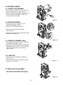
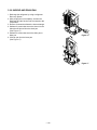
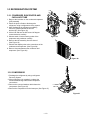
1
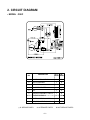
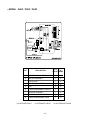
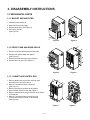
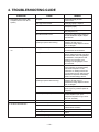
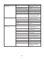
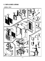
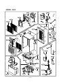
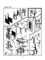
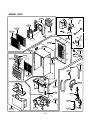
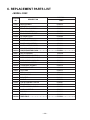
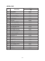
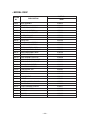
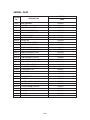
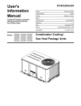
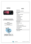
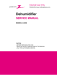
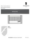
Dehumidifier
S ervic e and Parts
Manual
2h
TIM
4h
r. On
/Of
r. On
f
/Of
f
Hig
ER
L ow
h
S P FA N
EE
D
HU
S E MID
TT IT Y
IN
G
HU
C ONMI DIT
TR Y
OL
Au
to
P OW
Re s
B UC
F UL K E
L T
ta rt
ER
D30C D40C D50C D65C
DehumSvcParts (06/05)
P
CONTENTS
1. PREFACE
1.1 SAFETY PRECAUTIONS ...........................................................................................................................3
1.2 FEATURES AND DIMENSIONS ................................................................................................................3
1.2.1 FEATURES........................................................................................................................................3
1.2.2 DIMENSIONS ....................................................................................................................................3
1.3 SPECIFICATIONS ......................................................................................................................................4
1.4 CONTROL TYPE ........................................................................................................................................4
2. CIRCUIT DIAGRAM ............................................................................................................................5~6
3. DISASSEMBLY INSTRUCTIONS
3.1 MECHANICAL PARTS ...............................................................................................................................7
3.1.1 BUCKET AND AIR FILTER ...............................................................................................................7
3.1.2 FRONT CASE AND REAR GRILLE...................................................................................................7
3.1.3 CABINET AND CONTROL BOX .......................................................................................................7
3.2 CONTROL PARTS ....................................................................................................................................8
3.2.1 POWER CORD ASSEMBLY .............................................................................................................8
3.2.2 SENSOR ASSEMBLY .......................................................................................................................8
3.2.3 PWB(PCB) ASSEMBLY, MAIN .........................................................................................................8
3.2.4 CAPACITOR......................................................................................................................................8
3.2.5 MICRO SWITCH ASSEMBLY ...........................................................................................................8
3.2.6 CONTROL PANEL ............................................................................................................................9
3.2.7 FAN AND MOTOR.............................................................................................................................9
3.2.8 SHROUD AND DRAIN PAN ............................................................................................................10
3.3 REFRIGERATING SYSTEM.....................................................................................................................11
3.3.1 CONDENSER, EVAPORATOR AND CAPILLARY TUBE...............................................................11
3.3.2 COMPRESSOR ..............................................................................................................................11
3.4 HOW TO REPLACE REFRIGERATION SYSTEM ...................................................................................12
4. TROUBLESHOOTING GUIDE ...................................................................................................14
5. EXPLODED VIEWS ..........................................................................................................................16
6. REPLACEMENT PARTS LIST ...................................................................................................20
—2—
1. PREFACE
This Service Manual provides various service information, including the mechanical and electrical parts.
This dehumidifier was manufactured and assembled under the strict quality control procedures.
The refrigerant is charged at the factory. Be sure to read the safety precaution prior to servicing the unit.
1.1 SAFETY PRECAUTIONS
• Disconnect the power supply before servicing or replacing any component.
• Do not cut off the grounding prong or alter the plug in any manner.
1.2 FEATURES AND DIMENSIONS
1.2.1 FEATURES
• Quiet operation
• High efficiency
• Adjustable humidistat
• Automatic defrost
• Automatic shut-off
• Bucket-full indicator light
• Easy roll casters
• Removable & large capacity bucket.
• Washable air filter
• Two-speed fan
• Drain hose connection.
1.2.2 DIMENSIONS (mm/in)
385 (15 5/32)
4hr. On/Off
2hr. On/Off
HUMIDITY
CONTROL
High
340 (13 3/8)
BUCKET
FULL
Low
Auto Restart
FAN
SPEED
HUMIDITY
SETTING
POWER
540 (21 1/4)
TIMER
Figure 1
—3—
1.3 SPECIFICATIONS
MODELS
ITEMS
CAPACITY(Pints/24hrs)
POWER SUPPLY(Phase,V,Hz)
INPUT(W)
RUNNING CURRENT(A)
ENERGY FACTOR(L/kw.h)
REFRIGERANT
REFRIGERANT CHARGE, oz(g)
OPEN
CLOSE
THERMISTOR
COMPRESSOR MODEL No.
PROTECTOR
D30C
D40C
30
40
D50C
50
D65C
65
1Ø, 115V,60Hz
480
580
560
850
4.8
5.7
5.4
8.3
1.23
1.36
1.75
1.50
R22
3.53(100)
4.94(140)
7.93(225)
8.46(240)
33.8°F(1±0.5°C)
50°F(10±0.5°C)
QS064CAB
QS075CBA
QA075CDB
QA114CBD
OVERLOAD PROTECTOR FOR COMPRESSOR
INTERNAL PROTECTOR(FUSE)FOR MOTOR
40µF, 270VAC
35µF, 270VAC
35µF, 270VAC
35µF, 270VAC
Shaded pole motor, 91W/1.8A,
Shaded pole motor,72W/1.4A,Thermal cutoff:266°F/130°C
Thermal cutoff:266°F/130°C
CAPACITOR
MOTOR ASSEMBLY,SINGLE
SWITCH ASSEMBLY,MICRO
OUTSIDED MENSIONS
WxHxD,mm(in)
NET WEIGHT,kg(lbs)
15A/250VAC
385X540X340(15 5/32 x 21 1/4 x 13 3/8)
17.6(38.9)
17.6(38.9)
20.4(44.9)
22.2(48.9)
*NOTE:Specifications are subject to minor change without notice for further improvement.
1.4 CONTROL TYPE
4hr. On/Off
High
2hr. On/Off
Low
TIMER
FAN
SPEED
HUMIDITY
CONTROL
BUCKET
FULL
Auto Restart
HUMIDITY
SETTING
POWER
Figure 2
Fan Speed
• This controls the speed of the airflow.
• High: Fan speed is set to high.
• Low: Fan speed is set to low.
• When Fan Speed button is pressed, the fan speed
mode is changed.
Timer
• Press this button to select type of operation.
• Select continuous On for uninterrupted operation.
• Select either 2 or 4 hr. On/Off for cycled operation:
The unit will operate for 2 or 4 hours, and then shut
off completely for 2 or 4 hours.
The cycle repeats until you change the setting.
• When Timer button is pressed, the Timer indicator
lights shift as follow from 2hr.On/Off to 4hr.On/Off.
Bucket Full Indicator
• This light glows when the water bucket is full and needs
to be emptied.
Power
• Operation starts when this button is pressed and stops
when the button is pressed again.
Auto Restart
• Once power is restored after a power outage, the unit
returns to its previous operation setting after a 2 minute
delay.
The fan runs immediately when the power is restored.
Humidity Control
• This button controls the humidity in the room.
• Press
button to raise the humidity setting.
• Press
button to lower the humidity setting.
• The humidity setting can be set to a permanent "On"
setting or to a specific humidity setting between 35% and
70% in 5% increments.
• "On" setting: Dehumidifier runs continuously regardless
of humidity condition.
• 35% - 70% setting: Dehumidifier runs on and off
according to surrounding humidity conditions.
—4—
2. CIRCUIT DIAGRAM
• MODEL : D30C
DESCRIPTION
NO.
Q'TY
REPER SET MARKS
1
POWER CORD ASSEMBLY
1
S
2
MOTOR ASSEMBLY
1
S
3
CAPACITOR
1
S
4
COMPRESSOR, SET
1
S
5
OLP
1
S
6
PWB(PCB) ASSEMBLY, DISPLAY
1
S
7
SENSOR ASSEMBLY
1
S
8
SWITCH ASSEMBLY, MICRO
1
S
9
PWB(PCB) ASSEMBLY, MAIN
1
S
S: SERVICE PARTS
A: ALTERNATE PARTS
—5—
N: NOT SERVICE PARTS
• MODEL : D40C / D50C / D65C
DESCRIPTION
NO.
Q'TY
REPER SET MARKS
1
POWER CORD ASSEMBLY
1
S
2
MOTOR ASSEMBLY
1
S
3
CAPACITOR
1
S
4
COMPRESSORT,SET
1
S
5
OLP
1
S
6
PWB(PCB)ASSEMBLY,DISPLAY
1
S
7
SENSOR ASSEMBLY
1
S
8
SWITCH ASSEMBLY,MICRO
1
S
9
PWB(PCB)0ASSEMBLY,MAIN
1
S
S: SERVICE PARTS
A: ALTERNATE PARTS
—6—
N: NOT SERVICE PARTS
3. DISASSEMBLY INSTRUCTIONS
3.1 MECHANICAL PARTS
3.1.1 BUCKET AND AIR FILTER
4hr.
2hr.
4hr.
On/O
On/O ff
ff
2hr.
High
TIM
ER
On/O
On/O ff
ff
High
TIM
ER
Low
FAN
SPE
ED
Low
FAN
SPE
ED
HUM
SET IDIT
TIN Y
G
1. Press the power button off.
2. Disconnect the power supply.
3. Remove the bucket. (See Figure 3)
4. Pull out the air filter.
(See Figure 4)
HUM
SET IDIT
TIN Y
G
HUM
CON IDIT
TRO
Y
L
Aut
o Res
BUC
FULKET
L
tart
POW
ER
Figure 3
HUM
CON IDIT
TRO
Y
L
Aut
o Res
BUC
FULKET
L
tart
POW
ER
Figure 4
3.1.2 FRONT CASE AND REAR GRILLE
1. Remove 2 screws which fasten the front grille.
2. Pull the front grille forward and upward.
(See Figure 5)
3. Remove 6 screws that secure the rear grille.
4. Remove the rear grille. (See Figure 6)
4hr.
2hr.
On/O
On/O ff
ff
High
TIM
ER
Low
FAN
SPE
ED
HUM
SET IDIT
TIN Y
G
HUM
CON IDIT
TRO
Y
L
Aut
o Res
BUC
FULKET
L
tart
POW
ER
Figure 5
Figure 6
3.1.3. CABINET AND CONTROL BOX
1. Remove the Bucket, the air filter and front grille
according to the procedure above.
2. Remove 1 screw that fasten control box.
(See Figure 7)
3. Remove 8 screws on all sides of the cabinet.
4. Lift the cabinet from the base.(See Figure 7)
5. Remove a screw fasten the ground wire on the inside
of control box.
6. Remove 1 screw that fasten control box and
unhook control box from hook on the shroud.
(See Figure 8)
Figure 7
—7—
Figure 8
3.2 CONTROL PARTS
3.2.1 POWER CORD ASSEMBLY
1. After opening the control box, remove the screw
that holds the ground wire. (See Figure 9)
2. Disconnect the remaining leads of the power cord
from the PWB(PCB) ASSEMBLY, MAIN, then
remove it from the control box.
Figure 9
3.2.2 SENSOR ASSEMBLY
1. Disconnect the sensor assembly from the
PWB(PCB) ASSEMBLY, MAIN.
2. Pull out the humidity sensor from H/E.
3. Remove the thermistor from the holder.
(See Figure 10)
4. Disconnect the switch wires from the micro switch
assembly. (See Figure 10)
3.2.3 PWB(PCB) ASSEMBLY, MAIN
Figure 10
1. Disconnect all wires of the motor and the compressor
from PWB(PCB) ASSEMBLY, MAIN.
2. Remove the screw which fastens the PWB(PCB)
ASSEMBLY, MAIN and pull it out after unhooking
from 2 rectangular holes of the control box.
(See Figure 11)
3.2.4 CAPACITOR
1. Remove the screw that fastens the capacitor.
(See Figure 11)
2. Disconnect all wires from the capacitor and then
remove it from control box.
Figure 11
3.2.5 MICRO SWITCH ASSEMBLY
1. Turn the nut counterclockwise and pull out the
micro switch from the drain pan. (See Figure 12)
Figure 12
—8—
3.2.6 CONTROL PANEL
1. Disconnect the housing of the PWB(PCB)
ASSEMBLY, DISPLAY from PWB(PCB)
ASSEMBLY, MAIN .
2. Remove 6 screws that fasten the PWB(PCB)
ASSEMBLY, DISPLAY to the display cover.
(See Figure 13)
Figure 13
3.2.7 FAN AND MOTOR
1. Turn the nut left and pull out the fan by hands
carefully.
2. Remove 2 screws that fasten H/E.
3. Lift the H/E and turn the H/E around 45 degree
clockwise carefully. (See Figure 14)
4. Unfasten 3 screws that secure the Motor and ground
wire. (See Figure 15)
5. Remove the Motor.
Figure 14
Figure 15
—9—
3.2.8 SHROUD AND DRAIN PAN
1. Discharge the refrigerant by using a refrigerant
Recovery System.
2. After purging the unit completely, unbrace the
Discharge and the Suction tube connected to the
compressor.
3. Remove 2 screws that fasten the heat exchanger.
4. Unfasten 2 screws that secure the shroud on the
sides then lift shroud from the drain pan.
(See Figure 17)
5. Unfasten 2 screws that secure the drain pan to
base pan.
6. Lift drain pan from the base pan.
(See Figure 17)
Figure 16
Figure 17
—10—
3.3 REFRIGERATION SYSTEM
3.3.1 CONDENSER, EVAPORATOR AND
CAPILLARY TUBE
1. Remove the insulation on the condenser/evaporator
(H/E) assembly
2. Pierce the pinch-off tube to discharge the
refrigerant, using a refrigerant recovery system.
3. After discharging the refrigerant completely,
remove 2 screws between the shroud
and the H/E. (See Figure 18)
4. Lift the H/E and turn the H/E around 45 degree
counterclockwise carefully.
5. Unbraze each of interconnecting tubes of the
evaporator and condenser carefully.
6. Remove the H/E assembly from the shroud.
(See Figure 19)
7. Unbraze the capillary tube at the connections of the
condenser and evaporator. (See Figure 20)
8. Remove 4 screws between the condenser and
evaporator. (See Figure 20)
Figure 18
Figure 19
Figure 20
3.3.2 COMPRESSOR
1. Discharge the refrigerant by using a refrigerant
Recovery System.
2. After purging the unit completely, unbraze the
suction and discharge tubes at the compressor
connections.
3. Remove the nuts and washers which fasten the
compressor. (See Figure 21)
4. Remove the compressor from the base pan. (See Figure 21)
Figure 21
—11—
3.4 HOW TO REPLACE THE REFRIGERATION SYSTEM
1. When replacing a refrigeration component, be sure
to discharge the refrigerant system by using a
refrigerant recovery system.
2. After discharging the unit completely, remove the
desired component, and unbraze the pinch-off
tubes.
3. Solder service valves into the pinch-off tube ports,
leaving the valves open.
4. Solder the pinch-off tubes with service valves.
5. After doing the above procedures, the valve must
be closed and left in place on the system for any
subsequent procedures.
6. Evacuate as follows.
1) Connect the vacuum pump, as illustrated in
Figure 22A.
2) Start the vacuum pump, slowly open manifold
valves A and B two full turns counterclockwise
and leave the valves open.
The vacuum pump is now pulling through valves
A and B to valve C by means of the manifold
and entire system.
7. Recharge as follows :
1) Refrigeration cycle systems are charged from the
High-side. If the total charge cannot be put
in the High-side, the balance will be put in the
suction line through the access valve which you
installed as the system was opened.
2) Connect the charging cylinder as shown in Figure
22B.
With valve C open, discharge the hose at the
manifold connection.
3) Open valve A and allow the proper charge to
enter the system. Valve B is still closed.
4) If more charge is required, the high-side will not
take it. Close valve A.
5) With the unit running, open valve B and add the
balance of the charge.
a. Do not add the liquid refrigerant to the Lowside.
b. Watch the Low-side gauge; allow pressure to
rise to 30 lbs.
c. Turn off valve B and allow pressure to drop.
d. Repeat steps B and C until the balance of the
charge is in the system.
6) When satisfied the unit is operating correctly,
use the pinch-off tool with the unit still running
and clamp on to the pinch-off tube. Using a tube
cutter, cut the pinch-off tube about 2 inches from
the pinch-off tool. Use sil-fos solder and solder
pinch-off tube closed. Turn off the unit, allow it to
set for a while, and then test the leakage of the
pinch-off connection.
7) Remove the service valves.
CAUTION
If high vacuum equipment is used, just crack
valves A and B for a few minutes, then open
slowly with the two full turns counterclockwise.
This will keep oil from foaming and being drawn
into the vacuum pump.
3) Operate the vacuum pump for 20 to 30 minutes,
until 600 microns of vacuum are obtained. Close
valves A and B, and observe vacuum gauge for
a few minutes. A rise in pressure would
indicate a possible leak or moisture remaining in
the system. With valves A and B closed, stop
the vacuum pump.
4) Remove the hose from the vacuum pump and
place it on the charging cylinder.
Open valve C, Discharge the line at the manifold
connection.
5) The system is now ready for final charging.
—12—
Equipment needed: Vacuum pump, charging cylinder, manifold gauge, brazing equipment. pinch-off tool capable
of making a vapor-proof seal, leak detector, tubing cutter, hand tools to remove components, service valve.
EVAPORATOR ASSEMBLY
(LOW PRESSURE SIDE)
CONDENSER ASSEMBLY
(HIGH PRESSURE SIDE)
COMPOUND GAUGE
MANIFOLD
GAUGE
B
A
CAPILLARY
TUBE
SEE INSETS
BELOW
COMPRESSOR
LOW
HI
A
B
B
A
EXTERNAL
VACUUM PUMP
CHARGING
CYLINDER
C
Figure 22B-Charging
Figure 22A-Pulling Vacuum
—13—
4. TROUBLESHOOTING GUIDE
CONDITION
1. Dehumidifier does not start. (Both
compressor and fan motor do not
operate.)
CAUSE
REMEDY
No power
Check power supply at outlet.
Correct if none.
Poor plug contact at outlet.
Install plug properly or replace it.
Bucket is full.
If Auto Shut Off lights, empty the bucket
and replace properly.
Humidity control is in Off position
Turn the humidity control switch toward
Max.(35degrees,R.H.)
Wire disconnected or loose
Connect wire. Refer to wiring diagram for
terminal identification. Repair or replace
loose terminal.
Capacitor.
(Discharge capacitor before testing.)
Test capacitor.
Replace if not within ±10% of
manufacturer's rating. Replace if shorted,
open, or damaged.
Voltage (115V ± 10%)
It must be between 103.5V and 126.5V. If
not within limits, call an electrician
Wiring
Check the wire connections; If loose,
repair or replace the terminal. If the wires
are disconnected, refer to wiring diagram
for identification, and replace the wires.
Check the wire connections; If not
according to the wiring diagram, correct
the connections.
Defrost control
The Defrost control senses frost build-up
on the evaporator coil and automatically
shuts off the compressor. The fan
continues to run, drawing air across the
coil, and melting the frost. When the coil is
defrosted, the compressor automatically
restarts, and dehumidifying resumes.
Capacitor
(Discharge capacitor before servicing.)
Check the capacitor.
Replace if not within ±10% of
manufacturer's rating. Replace if shorted,
open, or damaged.
Compressor
Check the compressor for open circuit or
ground. If open or grounded, replace the
compressor.
Overload protector (OLP)
Check the compressor OLP if externally
mounted. Replace if open. (If the
compressor temperature is high, remove
OLP, cool, and retest.)
3. Does not defrost control
Defrost control is defective.
Check defrost control, replace it.
4. Insufficient dehumidification
Low relative humidity
Turn dehumidifier off.
Poor air circulation
Move dehumidifier to obtain free and
unobstructed air circulation.
H/E clogged with dust and dirt
Clean evaporator and/or condenser assembly
Air filter is dirty.
Clean it.
Motor is not operating.
Check Motor, repair or replace it.
2. Motor runs but compressor does not
run.
—14—
CONDITION
5. Noisy operation
6. Water drips
7. Compressor cycles on overload
protector. (OLP)
CAUSE
REMEDY
Fan
If cracked, out of balance, or partially
missing, replace it
Loose foreign material inside the housing.
Remove it.
Tube hits frame.
Adjust tubing routine carefully.
Fan blade hits frame
Check Motor Mount. If loose, tighten it.
Internal compressor noise.
Replace compressor.
Loose set screws
Tighten them.
Worn bearings of Motor Assembly
If knocking sounds continue when running
or loose, replace the motor. If the motor
hums or noise appears to be internal while
running, replace motor assembly.
The bucket is not installed properly.
The bucket should be properly positioned
on the hangers of the drain pan.
Connection may be loose.
Check connection and repair.
Leak in bucket
Replace bucket.
Water drips when bucket removed for
emptying.
Before removing bucket, the unit should
be turned off.
Bucket overflows.
Check micro switch and float.
High or low line voltage. (115V ± 10%)
Check line voltage. It must be between
103.5V and 126.5V volts.
If intermittent, provide new supply.
Poor air circulation.
Move dehumidifier for free and
unobstructed air flow.
Heat Exchanger clogged with dust or dirt.
Clean dust or dirt on the Heat Exchanger.
Motor
If not running, determine the cause.
Replace if required.
Short circuit or ground in electrical circuit
Check electrical circuit. Repair.
Unit pressures not equalized
Allow 2 or 3 minutes for pressure to
equalize before starting compressor.
Capacitor
Test the capacitor.
Wiring
Check the terminals. If loose, repair or
replace.
Refrigeration system
Check the system for a restriction.
Stuck compressor
Check compressor, replace compressor
Overload protector (OLP)
Check OLP, if externally mounted.
Replace if open. (If the compressor
temperature is high, remove the OLP,
cool, and retest.)
—15—
5. EXPLODED VIEWS
• MODEL: D30C
W0CZZ
149980
349600
554030
354210
268714
359012
264110
249950
346811
435300
162615
130900
135312
238310
268712
436500
352113
35211A
152302
266011
552111
752140
330870
567502
130411
554160
148390
144410
550140
—16—
• MODEL: D40C
149980
W0CZZ
349600
554030
354210
359012
268714
249950
346811
435300
264110
130900
162615
135312
238310
268712
436500
352113
35211A
152302
266011
552111
752140
330870
567502
130401
554160
148390
144410
550140
—17—
• MODEL: D50C
149980
W0CZZ
349600
554030
354210
359012
268714
249950
346811
435300
264110
130900
162615
135312
238310
268712
436500
352113
35211A
152302
266011
552111
752140
330870
567502
130401
554160
148390
144410
550140
—18—
• MODEL: D65C
149980
W0CZZ
349600
554030
354210
359012
268714
249950
346811
435300
264110
130900
162615
135312
238310
268712
436500
352113
35211A
152302
266011
552111
752140
330870
567502
130401
554160
148390
144410
550140
—19—
6. REPLACEMENT PARTS LIST
• MODEL: D30C
LOCATION
NO.
PART NO.
DESCRIPTION
D30C
130411
BASE ASSEMBLY
67500072
130900
CABINET
67400185
135312
FRONT GRILLE,ASSEMBLY
67306010
330870
DRAIN PAN ASSEMBLY
67500126
148390
TANK ASSEMBLY,BUCKET
67500083
152302
FILTER(MECH),AIR
67500098
162615
SENSOR ASEMBLY
67500099
249950
CONTROL BOX,ASSEMBLY
67500127
264110
POWER CORD,ASSEMBLY
67500024
266011
SWITCH ASSEMBLY,MICRO
67400136
268712
PWB(PCB)ASSEMBLY,DISPLAY
67500092
268714
PWB(PCB)ASSEMBLY,MAIN
67307604
346811
MOTOR ASSEMBLY
67500128
35211A
TUBE ASSEMBLY,SUCTION
67400210
352113
TUBE ASSEMBLY,DISCHARGE
67400212
552111
TUBE ASSEMBLY,CAPILLARY
67302126
354210
EVAPORATOR,ASSEMBLY
67400193
554030
CONDENSOR ASSEMBLY
67400128
554160
COMPRESSOR ,SET
67500123
359012
FAN,TURBO
67400133
567502
OLP
67301418
349600
MOUNT,MOTOR
67400112
W0CZZ
CAPACITOR
67400184
436500
HANDLE
67500078
144410
CASTER ASSEMBLY,ROLLER
67500061
238310
ESCUTCHEON
67500080
235512
COVER ASSEMBLY,DISPLAY
67500077
752140
HOSE,CONNECTOR
67500125
550140
BUSHING
67400109
149980
SHROUD
67500087
435300
REAR GRILLE
67307206
—20—
• MODEL: D40C
LOCATION
NO.
PART NO.
DESCRIPTION
D40C
130411
BASE ASSEMBLY
67500071
130900
CABINET
67400185
135312
FRONT GRILLE,ASSEMBLY
67306010
330870
DRAIN PAN ASSEMBLY
67500126
148390
TANK ASSEMBLY,BUCKET
67500083
152302
FILTER(MECH),AIR
67500098
162615
SENSOR ASEMBLY
67500093
W0CZZ
CAPACITOR
67400182
249950
CONTROL BOX,ASSEMBLY
67500084
264110
POWER CORD,ASSEMBLY
67500024
266011
SWITCH ASSEMBLY,MICRO
67400136
268712
PWB(PCB)ASSEMBLY,DISPLAY
67500092
268714
PWB(PCB)ASSEMBLY,MAIN
67307604
346811
MOTOR ASSEMBLY
67500081
35211A
TUBE ASSEMBLY,SUCTION
67400211
352113
TUBE ASSEMBLY,DISCHARGE
67500091
552111
TUBE ASSEMBLY,CAPILLARY
67500094
354210
EVAPORATOR,ASSEMBLY
67400188
554030
CONDENSOR ASSEMBLY
67400186
554160
COMPRESSOR ,SET
67500068
359012
FAN,TURBO
67400133
567502
OLP
67301414
349600
MOUNT,MOTOR
67400112
436500
HANDLE
67500078
144410
CASTER ASSEMBLY,ROLLER
67500061
238310
ESCUTCHEON
67500080
235512
COVER ASSEMBLY,DISPLAY
67500077
752140
HOSE,CONNECTOR
67500125
550140
BUSHING
67400109
149980
SHROUD
67500087
435300
REAR GRILLE
67307206
—21—
• MODEL: D50C
LOCATION
NO.
PART NO.
DESCRIPTION
D50C
130411
BASE ASSEMBLY
67500072
130900
CABINET
67400185
135312
FRONT GRILLE,ASSEMBLY
67306010
330870
DRAIN PAN ASSEMBLY
67500126
148390
TANK ASSEMBLY,BUCKET
67500083
152302
FILTER(MECH),AIR
67500098
162615
SENSOR ASEMBLY
67500099
W0CZZ
CAPACITOR
67400184
249950
CONTROL BOX,ASSEMBLY
67500127
264110
POWER CORD,ASSEMBLY
67500024
266011
SWITCH ASSEMBLY,MICRO
67400136
268712
PWB(PCB)ASSEMBLY,DISPLAY
67500092
268714
PWB(PCB)ASSEMBLY,MAIN
67307604
346811
MOTOR ASSEMBLY
67500081
35211A
TUBE ASSEMBLY,SUCTION
67500208
352113
TUBE ASSEMBLY,DISCHARGE
67400213
552111
TUBE ASSEMBLY,CAPILLARY
67400215
354210
EVAPORATOR,ASSEMBLY
67400216
554030
CONDENSOR ASSEMBLY
67400127
554160
COMPRESSOR ,SET
67500124
359012
FAN,TURBO
67400133
567502
OLP
67301417
349600
MOUNT,MOTOR
67400112
436500
HANDLE
67500078
144410
CASTER ASSEMBLY,ROLLER
67500061
238310
ESCUTCHEON
67500080
235512
COVER ASSEMBLY,DISPLAY
67500077
752140
HOSE,CONNECTOR
67500125
550140
BUSHING
67400109
149980
SHROUD
67500087
435300
REAR GRILLE
67307206
—22—
• MODEL: D65C
LOCATION
NO.
PART NO.
DESCRIPTION
D65C
130411
BASE ASSEMBLY
67500072
130900
CABINET
67400185
135312
FRONT GRILLE,ASSEMBLY
67306010
330870
DRAIN PAN ASSEMBLY
67500126
148390
TANK ASSEMBLY,BUCKET
67500083
152302
FILTER(MECH),AIR
67500098
162615
SENSOR ASEMBLY
67500099
W0CZZ
CAPACITOR
67400184
249950
CONTROL BOX,ASSEMBLY
67500086
264110
POWER CORD,ASSEMBLY
67500024
266011
SWITCH ASSEMBLY,MICRO
67400136
268712
PWB(PCB)ASSEMBLY,DISPLAY
67500092
268714
PWB(PCB)ASSEMBLY,MAIN
67307604
346811
MOTOR ASSEMBLY
67500129
35211A
TUBE ASSEMBLY,SUCTION
67400209
352113
TUBE ASSEMBLY,DISCHARGE
67400214
552111
TUBE ASSEMBLY,CAPILLARY
67302127
354210
EVAPORATOR,ASSEMBLY
67400217
554030
CONDENSOR ASSEMBLY
67400187
554160
COMPRESSOR ,SET
67500070
359012
FAN,TURBO
67400133
567502
OLP
67500055
349600
MOUNT,MOTOR
67400112
436500
HANDLE
67500078
144410
CASTER ASSEMBLY,ROLLER
67500061
238310
ESCUTCHEON
67500080
235512
COVER ASSEMBLY,DISPLAY
67500077
752140
HOSE,CONNECTOR
67500125
550140
BUSHING
67400109
149980
SHROUD
67500087
435300
REAR GRILLE
67307206
—23—
Us e F ac tory C ertified P arts ...
F R IE DR IC H AIR C ONDIT IONING C O.
V is it our web s ite at www.friedrich.com
P os t Office B ox 1540 • 4200 N. P an Am E xpres s way • S an Antonio, T exas 78295-1540
(210) 357-4400 F AX (210) 357-4480
P rinted in the U.S .A
DehumSvcParts (06/05)