1
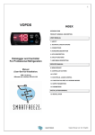
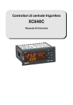
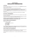
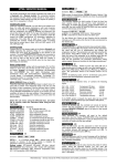
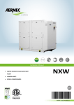
1
INDEX
VOPOS
USER MANUAL
1. SAFETY
2. TECHNICAL SPECIFICATIONS
3. CONNECTIONS
4. KEYBOARD DESCRIPTION
5. KEYS DESCRIPTION
6. HACCP FUNCTIONS
7. USER MENU DESCRIPTION
Temperature and Humidity
High Performance Controller
for Uprights and Refrigerated
Tables
SERVICE MANUAL
8. MENU SERVICE
9. CONTROLLER ACTIONS
10. D-TEST
11. ELECTRICAL LOADS CONTROL
Manual
(User-Service-Installation)
12. FUNCTION FAILURES VS. WORKING MODES
13. SUPER PARAMETERS
14. PARAMETERS
INSTALLATION MANUAL
15. INSTALLATION
SMARTFREEZE
2
USER MANUAL
1. SICUREZZA
1.
2.
3.
4.
5.
6.
Hold the present booklet in a sit where the
consultation it is easily for the user.
Do not power on the controller after or during
installation,
any
mechanical
or
electrical
intervention since there are some connectors
under high voltage inside.
In the controller case there aren’t components that
can be managed by the user.
VOPOS controllers don’t have any protection of
connected loads. Therefore all the loads should be
protected for short circuits, for high/low currents,
and for right temperatures by appropriate devices
as fuses, magneto-thermal switches, etc…
Violation of safety rules during the installation and
failure to comply with the instructions contained in
this manual may affect the overall safety level of
controllers.
VOPOS Controllers are free from electromagnetic
emission according to EEC Directives. To reduce
the causes of disorders such radiated or
conducted, which can propagate through the
probes, loads and controller power supply, you
must do the wiring of the cables preventing their
passage close to the absorption of high loads or
sources of electromagnetic disturbances.
7.
It necessary to put temperature probes in contact
with food, verify that these comply with food and
health requirements.
8.
If the controllers will be installed in devices whose
malfunctioning may generate hazard for people,
animals or things, it must be adopted extra safety
systems that operate independently of the
controllers.
2. TECHNICAL SPECIFICATIONS
2.1 Mechanics
ABS case, size 32x74mm
2.2 Supply
Switching 110-230V 50/60Hz with an input for back up
(12V cc/5V cc)
2.3 Probes inputs
Range
Resolution
S1: ntc thermoregulation (-50.0, +50.0°C) 0,1°C
S2: ntc evaporator
S3: ntc condenser/alarm (-20.0, +80.0°C) 0,1°C
S4: digital/4-20mA
(10-99 Rh%)
1%
Internal current probe
(0-20A)
0,1A
(-50.0, +50.0°C) 0,1°C
2.4 Relè outputs
4 relè 20A-8A-5A-5A (one is a switch N.C./N.A.)
2.5 User interface
Touch pad with 4 keys and a menu configuration;
Led display with 3 alphanumeric digits 7x5 segments
(for a total of 7x15 dots) and with sliding words
2.6 Communication
RS485 to connect to local networks and Smartfreeze
Unit (SFU) for remote Monitoring and Control;
Mini USB to upgrade firmware, to setting parameters
(in/out), to download temperature recording data, to
upload refrigerator bill (materials) and to record start
up data.
SMARTFREEZE
3
3. CONNECTIONS
VOPOS
CONTROLLER
CVC44
Made in Italy
BUZZER INSIDE
Inputs
S1
S2
S3
S4*
S4
Thermostat ntc probe
Evaporator ntc probe
Monitor/Condenser ntc probe
Humidity Sensor 12V, 4-20mA
Digital Door Switch
Outputs
SN:
00000
030
PN:
74193
V12
RL1 30A rele res[1.5HP – 230V]
RL2a 8A rele n.o. resistive
RL2b 8A rele n.c. resistive
RL3 5A rele resistive
RL4 5A rele resistive
L
Common Line
OUTPUTS
SUPPLY
110-240 VAC
50/60Hz 3VA
~
~
RL4 RL2b RL2a RL3
RS485 RS485 +
GND
+5V
*S4
*S4 +12V
6
5
4
3
2
1
INPUTS
MAX
20 A
RL1
SMARTFREEZE
L
S1 S2 S3 C S4 S4
4
4. KEYBOARD DESCRIPTION
The keyboard is a touch pad with 4 keys.
MENU/
ESC KEY
UP/
LIGHT KEY
OK KEY
DOWN/
INFO KEY
5. KEYS DESCRIPTION
•
•
•
•
MENU/ESC KEY: by this key, from the operation
mode, the controller accesses Menu; from other levels
or when the controller displays a message or an
information string, it has the function of ESC.
OK KEY: it confirms the required action. During the
controller operation mode, without pressing MENU
key, it allows to display the current date and time.
UP/LIGHT KEY: in normal display mode, it enables
the UP function, after the selection of MENU for
scrolling menu and submenu items. It increases the
SET POINT and/or parameters values. If it has been
scheduled PSO super parameter (for super
parameters details, see paragraph 13), the key,
pressed for 2 seconds, enables the function LIGHT
and allows to turn on (LIGHT ON message) and off the
light (LIGHT OFF message).
DOWN/INFO KEY: in normal display mode, it enables
the DOWN function, after the selection of MENU for
scrolling by menu and submenus items. It decreases
the SET POINT and/or parameters values. It enables
INFO function, when it is pressed for 2 seconds, and
enables the information string with the % of operating
compressor in the last hour, of the evaporator and
condenser temperatures (if enabled), of the
instantaneous consumption and, ultimately, of the last
temperature alarm data, if it happened (alarm type,
maximum temperature for high temperature alarm and
minimum temperature for low temperature alarm, with
date/ time of start event).
EX. WITH RECORDED ALARM
• K45%; TE -24°C TC 56°C; WATT 230; HIGH
TEMPERATURE; MINUTES 12; MAX +23°C; 12/08/09
23:56
EX. WITH NOT RECORDED ALARM (if % non calculated =
--%)
• K45%; Te-24°C; Tc+56°C; WATT 230
5.1 Controller turning on
To turn on the controller, in stand-by mode (the display
shows the following symbol ---), pressing any key for longer
than 2 seconds.
The controller displays the message TO TURN ON OK; TO
ESCAPE ESC.
Choosing OK, the controller displays the message DONE,
WELCOME and starts to adjust, displaying the cold room
temperature.
Choosing ESC, the controller leaves the turning on and
returns to stand-by mode.
If PSU parameter is >0 (for parameters details, see
paragraph 14), before the turning on, the controller displays
the message PASSWORD and stops on the three digits
000. The PASSWORD is setting by UP/DOWN keys and
confirmed by OK key.
If the password is correct, the controller turns on.
If the password is not correct, the controller displays the
message WRONG PASSWORD and returns to stand-by
mode.
5.2 Normal displaying mode
In normal displaying mode, the controller displays the cold
room temperature (Probe S1) or the probe alarm
temperature, depending on the configuration chosen by the
manufacturer.
The temperature scale will be shown in tenths of degree
Celsius with a minus sign (only for negative values) for a
range between -29.9° C and +69.9°C. Below the lower
limit, the temperature appears with °C sign and sca le.
If the compressor is activated, temperature displaying is
alternating by the message COOLING or, in defrost case,
by the message DEFROST.
5.3 Displaying mode in case of event
If fault, warning or alarm occur, the controller displays the
event alternated by the cold room temperature until the
event is corrected, with an option to append more events.
•
MESSAGES OF FAILURE (variables are shown in
bold italics)
The occurrence of one of the following messages requires
a technician intervention.
PROBE FAIL SX
LOAD –RLXDEFROST TIME OUT
HIGH CONDENSATION 65°C
LOW EVAPORATION -29°C
LOW GAS
PCB TEMPERATURE (CIRCUIT TEMPERATURE) 76°C
TEST TIME-OUT
DIRTY CONDESER
COMPRESSOR USAGE
NO PEN DRIVE
PEN-DRIVE LOCKED
FILE ERROR
NO FILE
FULL MEMORY
•
WARNING MESSAGES
The occurrence of one of the following messages requires
attention by the user.
•
ALARM MESSAGES (see paragraph 6)
HIGH TEMPERATURE
LOW TEMPERATURE
6. HACCP FUNCTIONS
With reference to the HACCP standards (Reg CE
852/2004), that require the continuous monitoring of
product conservation temperatures, a procedure has been
developed to record temperature alarms, divided into two
types:
•
•
high temperature inside the cold room,
low temperature inside the cold room.
Monitoring probe can be S3 set as alarm probe or the
same probe set as regulation probe S1. The controller
records the last 32 events on a revolving manner while only
the last one is shown on the display. For each alarm event
the following data are recorded:
•
•
•
duration of event,
peak temperature,
start date/time of event.
SMARTFREEZE
5
6.1 Temperature pre-alarm
If
there
is
an
High
Temperature
pre-alarm
(temperature>SPU+ALH. For parameters details, see
paragraph 14), the controller displays the cold room
temperature
alternated
by
the
message
HIGH
TEMPERATURE, only if it has been scheduled VSP super
parameter (for super parameters details, see paragraph
13).
If
there
is
a
Low
Temperature
pre-alarm
(temperature<SPU+ALL. For parameters details, see
paragraph 14), the controller displays the message LOW
TEMPERATURE, without the event is recorded.
6.2 Temperature alarm
If
there
is
an
High
Temperature
alarm
(temperature>SPU+ALH for longer than ALD min. For
parameters details, see paragraph 14), the controller
displays the message HIGH TEMPERATURE, with the
buzzer that will sound until the temperature returns within
the set limits.
If
there
is
a
Low
Temperature
alarm
(temperature<SPU+ALL for a time longer than ALD min.
For parameters details, see paragraph 14), the controller
displays the message LOW TEMPERATURE, with the
buzzer that will sound until the temperature returns within
the set limits.
6.3 Alarm end
If it has been scheduled VSP super parameter (for super
parameters details, see paragraph 13), when alarm ends,
the controller displays the message PUSH INFO KEY
alternated by the cold room temperature until INFO is read.
This message informs the user that some alarms have
been occurred, if he did not red the message or he did not
hear the buzzer.
6.4 Buzzer turning off
The buzzer will be stopped by pressing any key.
For temperature alarms, the buzzer turning off inhibits even
the message PUSH INFO KEY. The buzzer can be
enabled and disabled by the schedule of VSP super
parameter (for super parameters details, see paragraph
13).
6.4.1 Buzzer reiteration and persistence
Parameter BUR (for parameters details, see paragraph 14)
represents the time, in minutes, of buzzer reiteration. The
reiteration implies the buzzer reactivation, after the buzzer
has been stopped by the key board, with the alarm still
persisting.
With the parameter BUR=0, the buzzer reiteration is
disabled.
Parameter BUF (for parameters details, see paragraph 14)
sets the time the buzzer will sound, without the turning off.
After BUR time, the buzzer starts again and gets repeated
after BUR minutes.
If BUF=0 buzzer stays on until the alarm end.
7. USER MENU DESCRIPTION
User Menu is accessible by pressing the MENU key; for
scrolling each item use UP and DOWN keys.
Below is a list of features visible using the DOWN key.
Warning!
The items listed by the dotted are viewable only if their
function is previously enabled.
OFF
Controller switching off
SET
Cold room temperature setting
Rh%
Humidity setting
DEF
Starting manual defrost
DOO
Door traffic displaying
Date/Time setting
0:0
USB
H12
M19
D06
M02
Y10
Pen drive functions
PAS
User password setting
LAN
Changing Language
SER
Technical support functions
WAT
Energy meter
7.1 Controller turning off
OFF - In the operation mode, pressing MENU key, the
controller displays the message OFF.
Pressing OK, it displays the message TO TURN OFF OK;
TO ESCAPE ESC.
Choosing OK, the controller displays the message DONE,
BYE. Then it turns off and returns to stand-by mode,
displaying the symbol ---.
Choosing ESC, the controller leaves the turning off and
returns to operation mode.
If PSU parameter is >0 (for parameters details, see
paragraph 14), before the turning off, the controller displays
the message PASSWORD and stops on the three digits
000. The PASSWORD is setting by UP/DOWN keys and
confirmed by OK key.
If the password is correct, the controller turns off.
If the password is not correct, the controller displays the
message WRONG PASSWORD and returns to the Menu
item OFF.
7.2 Cold room temperature setting
SET - From the Menu item SET, pressing OK key, the
controller displays the message SET TEMPERATURE and
stops on the operating temperature set point that can be
changed by UP/DOWN keys.
SMARTFREEZE
6
Pressing OK key, the controller displays the message TO
CONFIRM OK; TO ESCAPE ESC.
Choosing OK, the controller displays the message DONE.
The value of the new set is confirmed by flashing the digits
and a short beep of the buzzer. Since then, the controller
adjusts the temperature with reference to the new set point.
Choosing ESC, the controller leaves the temperature
setting and adjusts the temperature with reference to the
old set point.
If PSU parameter is >0 (for parameters details, see
paragraph 14), before the temperature setting, the
controller displays the message PASSWORD and stops on
the three digit 000. The PASSWORD is setting by
UP/DOWN keys and confirmed by OK key.
If the password is correct, the controller allows the cold
room temperature setting.
If the password is not correct, the controller displays the
message WRONG PASSWORD and returns to the Menu
item SET.
7.3 Humidity setting
RH% - If it hasn’t been scheduled DOP super parameter
(for super parameters details, see paragraph 13), the
humidity control is not enabled and, in the Menu, there isn’t
the item RH%.
From the Menu item RH%, pressing OK key, the controller
displays the message SET HUMIDITY and stops on
operating humidity set point that can be changed by
UP/DOWN keys.
Pressing OK key, the controller displays the message TO
CONFIRM OK; TO ESCAPE ESC.
Choosing OK, the controller displays the message DONE.
The value of the new set is confirmed by flashing the digits
and a short beep of the buzzer. Since then, the controller
adjusts the humidity with reference to the new set point.
Choosing ESC, the controller leaves the setting of the
humidity and adjusts the temperature with reference to the
old set point.
7.4 Starting manual defrost
DEF - If it hasn’t been scheduled VSP super parameter
(for super parameters details, see paragraph 13), the
manual defrost is not enabled and, in the Menu, there isn’t
the item DEF.
From the Menu item DEF, pressing OK key, the controller
displays the message TO DEFROST OK; TO ESCAPE
ESC.
Choosing OK, the controller displays the message DONE
and, if there are the right conditions, it starts defrost and
displays the message DEFROST.
If there aren’t the right conditions for defrost, the controller
displays the message ACCESS DENIED and the
temperature. If defrost is pending, the controller displays
the message WAITING DEFROST alternated by the
temperature until the defrost starting.
Choosing ESC, the controller leaves the defrost and
displays the cold room temperature.
7.5 Door traffic displaying
DOO - If it hasn’t been scheduled DOO super
parameter (for super parameters details, see paragraph
13), the monitoring of door openings is not enabled and, in
the Menu, there isn’t the item DOO.
From the Menu item DOO, pressing OK key, the controller
displays the door traffic list of the 2 last days:
ES.
• OPENING FOR MINUTES TODAY 034 021 CRITICAL 001;
OPENINGS 11/08/09 012 FOR MINUTES 000.
If there aren’t door traffic events, the controller displays the
message NO EVENTS.
7.6 Date/Time setting
0:0 - From the Menu item 0:0, pressing OK key, the
controller displays time digits that can be changed by
UP/DOWN keys.
Pressing OK key, the controller displays progressively
minute digits, day, month and year. The confirmation of the
selected data is set by pressing OK key.
Pressing ESC key, the controller leaves the data/time
setting in every phase: hour H, minutes M, day D, month M,
year Y.
Warning!
Confirming the value of the year Y, date-time setting
causes the automatic memory cancellation and the
controller displays the message MEMORY RESET.
If PSU parameter is >0 (for parameters details, see
paragraph 14), before the Data/Time setting, the
controller displays the message PASSWORD and
stops on the three digits 000. The PASSWORD is
setting by UP/DOWN keys and confirmed by OK key.
If the password is correct, the controller allows the
Date/Time setting.
If the password is not correct, the controller displays
the message WRONG PASSWORD and returns to the
Menu item 0:0.
7.7 USB functions
USB - Warning!
Before entering this Menu item, put the pen drive, with
its adapter, in controller USB port.
From the Menu item USB, pressing OK key, the controller
displays the submenu item SAVE PARAMETERS. By
UP/DOWN keys, it is possible to scroll other submenu
items: LOAD PARAMETERS, UPGRADE FIRMWARE,
DOWNLOAD DATA, MATERIALS, STARTUP.
If the pen drive isn’t on, the controller displays the message
NO PEN DRIVE.
If the per drive is on, but it is write protected, the controller
displays the message PEN DRIVE LOCKED.
7.7.1 Save parameters
From the Menu item USB/SAVE PARAMETERS, pressing
OK key, the controller saves parameters in the pen drive,
creating the file “param00.par”.
If in the pen drive there is another file with the same name,
the controller creates a file “param01.par” and so on.
7.7.2 Load parameters
From the Menu item USB/LOAD PARAMETERS, pressing
OK key, the controller updates the parameters, read from
the file "param.par" that is in the pen drive root.
Warning!
If this file is not present in pen drive root or if it has
another name, the controller displays the message NO
FILE and it doesn’t load the parameters.
The controller is associated with a parameters and super
parameters setting utility, available in the DOWNLOAD
section
of
Smartfreeze
SERVICE
area:
http://service.smartfreeze.com.
7.7.3 Update firmware
From the Menu item USB/UPDATE FIRMWARE, pressing
OK key, the controller starts the update procedure, if there
is the file “Vopos.bin” in the pen drive root.
Smartfreeze periodically releases firmware updates that
can be downloaded from its website.
Warning!
For firmware upgrade, use only the files released by
SMARTFREEZE
7
Smartfreeze.
Smartfreeze is not responsible for any malfunction of
the controller caused by files derived from other
sources.
7.7.4 Download data
From the Menu item USB/DOWNLOAD DATA, pressing
OK key, the controller starts the transfer of temperature
recorded data on the pen drive, creating the file
"thermo00.csv”
If in the pen drive there is another file with the same name,
the controller creates a file “thermo01.csv” and so on.
The controller is associated with an utility for the displaying
of temperature data recorded, available in the DOWNLOAD
section
of
Smartfreeze
SERVICE
area:
http://service.smartfreeze.com.
7.7.5 Materials
From the Menu item USB/MATERIALS, with a setting file
which the refrigerator manufacturer would have, it is
possible to add the list of refrigerator materials (refrigerator
bil), with their PART NUMBER and descriptions.
7.7.6 Start up
This menu item is disabled to the user and is restricted to
Smartfreeze for the controller startup procedure.
controller displays submenu item KWH CURRENT.
By UP/DOWN keys, it is possible to scroll the other
submenu items: WH HOURLY and KWh DAILY.
7.10.1 KWh current
From the Menu item WAT/KWH CURRENT, pressing OK
key, the controller displays the value of energy totalized
from 00:01 on the current day.
7.10.1 WH hourly
From the Menu item WAT/WH HOURLY, pressing OK key,
the controller displays the value of energy totalized in the
previous hour.
7.10.1 KWh daily
From the Menu item WAT/KWh DAILY, pressing OK key,
the controller displays the value of energy totalized in the
previous day.
SERVICE MANUAL
8. MENU SERVICE
INF
Information – it shows the daily % and the
previous 24h % of compressor usage; the
calibration values and the PCB temperature
7.7 User password setting
PAS
- From the Menu item PAS, pressing OK key, the
controller displays the message SETUP PASSWORD and
stops on the three digits 000 that can be changed by
UP/DOWN keys.
Pressing OK key, the controller displays the message TO
CONFIRM OK; TO ESCAPE ESC.
Choosing OK, the controller displays the message DONE.
The value of the new PASSWORD is confirmed by flashing
the digits and a short beep of the buzzer. Since then, the
controller allows the access to protected functions just by
setting the new password.
Choosing ESC, the controller leaves the password setting
and displays the cold room temperature.
If PSU parameter is >0 (for parameters details, see
paragraph 14), before the password setting, the controller
displays the message PASSWORD and stops on the three
digits 000. The PASSWORD is setting by UP/DOWN keys
and confirmed by OK key.
If the password is correct, the controller allows the
password setting.
If the password is not correct, the controller displays the
message WRONG PASSWORD and returns to the Menu
item PAS.
DEF
Defrost List – it shows the last 2 defrost
events
!
PAR
Parameters setting – it allows the parameters
setting
TST
D-Test – it starts routine test
DAT
D-Test Data – it shows the data test
CLR
7.8 Changing language
LAN - From the Menu item LAN, pressing OK, the
controller displays the language item ITALIAN. By
UP/DOWN keys it is possible to scroll other languages
items: FRENCH, GERMAN, SPANISH, AND ENGLISH.
Pressing OK key, the controller displays the message TO
CONFIRM OK; TO ESCAPE ESC.
Choosing OK, the controller displays the message DONE
and the cold room temperature.
Choosing ESC, the controller leaves the changing
language displays the cold room temperature.
7.9 Technical support functions
SER - Access to Menu item SER is under password and
Failure List – it shows the last 2 failure
events
Erasing Events – It erase memory
events
I/O
Input/Output – it shows probe temperature and
relays RL1, RL2, RL3, RL4 condition
FW
Firmware Version – it shows firmware
version
SN
is reserved for technical support.
7.10 Energy meter
WAT - From the Menu item WAT, pressing OK key, the
SMARTFREEZE
Controller Serial Number – it shows the
controller serial number
8
8.1 Information
INF
- From submenu item SER/INF, pressing OK key,
the controller displays information for the technical support.
EX
• 1h=45% 24h=67% - % Compressor usage in the last hour
and in the last 24 hours; % not calculated;
• E MIN-23°C /MAX-34°C/CYCLES 06 - Calibration values :
min and max evaporation and number cycles for
calibration ;
• DELTA 18°C RANGE 65°C/34°C - Average adjusted
value of condenser thermal exchange and min-max
adjusted values in detection criteria of dirty condenser;
• BOARD 76°C - Vopos board temperature .
8.2 Defrost List
DEF
- From submenu item SER/DEF, pressing OK key,
the controller displays the 2 last defrost events data,
starting with the most recent.
If there aren’t data, the controller displays the message NO
EVENTS and returns to submenu SER/INF.
EX.
• Most recent event: MINUTES 012 23:45 03/08/09 M101;
• Older event: MINUTES 008 10:49 03/08/09 M09
For the details of defrost causes (MXX) see paragraph 9.9.
8.3 Failure List
! -
From submenu item SER/!, pressing OK key, the
controller displays the 2 last failure events data, starting
with the most recent.
If there aren’t data, the controller displays the message NO
EVENTS and returns to submenu SER/INF.
EX.
• Most recent event: PROBE S2 11-08-09 10:07;
• Older event: DEFROST M 03-08-09 23:57
8.4 Parameters setting
PAR - From submenu item SER/PAR, pressing OK key,
the controller displays the first parameter. The parameters
can be selected by UP/DOWN keys. For choosing the
parameter to modify, press OK key.
Then the controller displays the current parameter value.
By UP/DOWN keys, it is possible to select the new
parameter value and confirm it pressing OK key. The new
parameter value is confirmed by flashing the digits, a short
beep of the buzzer and then the controller displays the next
parameter. Since then, the controller adopts the new
parameter value.
Choosing ESC, the controller leaves the parameters setting
and displays the last parameter selected.
The exit from the submenu for parameters setting is for 4
minutes time-out or by pressing MENU key for 5
seconds.
8.5 D-Test
TST
- From submenu item SER/TST, pressing OK key,
the controller displays the message TO START TEST OK;
TO ESCAPE ESC.
Choosing OK, the controller starts the routine test and
displays the message DONE.
During the test the controller displays the cold room
temperature alternated by the message that indicates the
current phase with its label (for test steps details, see
paragraph 10). In each test phase, by UP/DOWN keys, it is
possible to get the following information: by UP key, the
phase duration in hours and minutes; by DOWN key, S2
and S3 probes temperatures and consumption in Watts.
At the end of the test, the controller displays the message
TEST END and adjusts with reference to the setting
parameters. To delete the message TEST END it is
necessary to turn off and on the controller or to interrupt the
power supply.
Warning!
During the test, high and low temperature alarms are
disabled. During the test, any fault, parameter or set
point change stops the test.
The
controller
displays
the
message
TEST
DISCONTINUED. The restart is made by Menu, but the
message can be deleted by manual restart or by
turning off and on again the controller.
Stops (black-out) and starts of energy do not erase the
message TEST DISCONTINUED. In the case of blackout during the test, it remains pending and begins
again to restore supply.
It is possible to stop the test, by pressing UP key for 5
seconds and the controller displays the message TEST
DISCONTINUED, which can be deleted according to the
procedure described above.
8.6 D-Test data
DAT - From submenu item SER/DAT, pressing OK key,
the controller displays the D-Test report.
If there aren’t data, the controller displays the message NO
DATA and returns to Menu SER.
EX.
• START TEST M12 S22 KW 3,1 - Duration and
consumption;
• DEFROST M5 S3 KW 0,7 - Defrost duration in Ph2 and
consumption;
• PULL-UP 230s/°C; PULL-DOWN 668s/°C - Test pending i n
phases 4 and 5 in seconds/degrees.
8.7 Events erasing
CLR - From submenu item SER/CLR, pressing OK key,
the controller displays the message TO ERASE OK; TO
ESCAPE ESC. Pressing again OK key, the controller
displays the message DONE and returns to submenu
SER/INF.
8.8 Input/Output
I/O - From submenu item SER/I/O, pressing OK key, the
controller displays information for technical support.
EX.
• S1=-19,7°C; S2=-34.3°C; S3=53, 5°C; S4=49 RH% Temperatures read by installed probes; missing or faulty
probes are ignored
• RL1 ON, RL2 OFF, RL3 OFF, RL4 ON - State of relays RL
1 2 3 4.
If S3 is configured as digital probe or it is not
installed, the related information are not displayed;
If S4 is configured as digital probe or it is not
installed, the related information are not displayed.
8.9 Firmware version
FW
- From submenu item SER/FW, pressing OK key,
the controller displays the firmware version and returns to
submenu SER/INF.
8.10 Controller serial number
SN - From submenu item SER/SN, pressing OK key, the
controller displays its serial number and returns to
submenu SER/INF.
SMARTFREEZE
9
9. CONTROLLER ACTIONS
9.1 Cooling
Related parameters
SET- (-40.0, 40.0;0.1) °C set-point settable from use r
menu
HYH - (0.0, 10.0;0.1) °C - adjustment top hysteresi s point
HYL - (0.0, 10.0;0.1) °C - adjustment lower hystere sis point
ASS - (0, 255;1) sec - compressor start delay
ADL - (0, 255;1) sec-cycling prevention (minimum time
between two compressor starts )
DAC - (0, 10;1) sec - delay time for compressor turns off.
Cooling transfer
Cooling is transferred to any of the relays by setting value
01 on relay parameter RLx (for parameters details, see
paragraph 14).
9.1.2 Logic
Cooling is done with higher and lower bandwidth with
reference to the set point and the HYH and HYL
differentials (for parameters details, see paragraph 14).
Compressor stops when the value measured by probe S1
reaches [SET-HYL]°C value, after time DAC (for
parameters details, see paragraph 14).
Compressor restarts when the value measured by probe
S1 reaches [SET+HYH]°C value.
The ADL anticycling parameter (for parameters details, see
paragraph 14) prevents compressor short cycles during
thermoregulation cycles.
ASS parameter represents the compressor delay at
controller power on by the keyboard or after the restoration
of power supply (for parameters details, see paragraph 14).
Warning!
Setting HYH=0, the controller stops temperature alarms
regulation and recording.
9.2 Defrost
Related parameters
DOP (0, 255;1) - num defrost limits exceeded
FOP (0, 255;1) - num fan parameters exceeded
DTE (0, 20;1) °C - temperature at defrost end refer red to
S2
DTO (0, 60;1) - min defrost maximum time
DRP (0.255;1)sec - drip time
ITD (2,24;1) hours - interval between defrost
SD1 (0,24;1) min - time start 1st programmed defrost
SD2 (0,24;1) min - time start 2nd programmed defrost
SD3 (0,24;1) min - time start 3rd programmed defrost
SD4 (0,24;1) min - time start 4th programmed defrost
Defrost transfer
Defrost is transferred to any of the relays by setting value
02 on relay parameter RLx (for parameters details, see
paragraph 14).
9.2.1 Defrost types
The controller handles several types of defrost,
programmable by DOP super parameter (for super
parameters details, see paragraph 13).
•
Defrost by compressor off,
•
Electric defrost,
•
Hot gas and inverted cycle defrost.
9.2.1.1 Defrost by compressor off
Defrost by compressor off stops the compressor by the
action of the evaporator fans up to the conditions of defrost
end (S2> DTE or DTO expired) (for parameters details, see
paragraph 14).
9.2.1.2 Electric defrost
Electric defrost turns off the compressor by the operation of
defrost heater up to the conditions of defrost end (S2> DTE
or DTO expired) (for details of the parameters, see
paragraph 14).
9.2.1.3 Hot gas and inverted cycle defrost
Hot gas and inverted cycle defrost turns on the compressor
and opens the defrosting valve up to the conditions of
defrost end (S2> DTE or DTO expired) (for parameters
details, see paragraph 14).
9.2.2 Types of defrost starting
The controller handles several types of defrost starting,
programmable by DOP super parameter (for super
parameters details, see paragraph 13).
The interval between defrosts is expressed by ITD
parameter (for parameters details, see paragraph 14).
Defrost starts in different ways, whose index m is shown in
the defrost list, viewable by the submenu item SER/DEF
(see paragraph 8). Defrosts, which can occur with or
without evaporator S2 probe installed, are as follows:
m1 manual defrost by keyboard
m2 defrost by serial command
m3 automatic defrost at every IDT hours
m5 automatic defrost at RTC time
m6 automatic defrost by D-Test
m7 automatic defrost in absence of calibration data
m8 automatic defrost by insufficient evaporation
m9 automatic defrost by excessive evaporation
m10 automatic defrost by calibrated protection
m11 automatic defrost by time protection
m12 automatic protection defrost by low temperature
evaporation
9.2.2.1 M1 -Manual defrost by keyboard
Manual defrost is enabled by the right value of DOP super
parameter (weight 1) (for super parameters details, see
paragraph 13) and it starts by menu item DEF (see
paragraph 7).
Electric Defrost
It starts immediately if the S2 evaporator temperature is
less than DTE (for parameters details, see paragraph 14).
Hot gas defrost
It starts when set point is reached, if the S2 evaporator
temperature is less than DTE with DOP parameter weight
64 (for super parameters details, see paragraph 13).
Where set point value is not reached within a maximum
time of 20 minutes after manual defrost, it however starts.
During the waiting period, the controller displays the
message WAITING DEFROST.
9.2.2.2 M2 - Defrost by serial command
Defrost can be started by a serial command of REALOAD
software or by SFU (Smartfreeze Unit for Remote
Monitoring and Control), if is connected to Vopos.
Defrost starts at once or at the end of compressor cycle
with DOP weight 64 (for super parameters details, see
paragraph 13) and if S2 temperature is lower that DTE°C
(for super parameters details, see paragraph 13).
9.2.2.3 M3 - Automatic defrost at every IDT hours
Defrost can be started at time intervals set by ITD
parameter in hour (for parameters details, see paragraph
14), enabled by DOP weight 3 (for super parameters
details, see paragraph 13).
Defrost starts at once or at the end of compressor cycle
with DOP weight 64 (for super parameters details, see
paragraph 13) and if S2 temperature is lower that DTE°C
(for super parameters details, see paragraph 13).
9.2.2.4 M5 - Automatic defrost at RTC time
SMARTFREEZE
10
Defrost can be started at a determinate time setting DOP
parameter weight 16 (for super parameters details, see
paragraph 13).
Defrosts day-time may be up to 4 hours beginning at SD1,
SD2, SD3, SD4. Defrost starts at once or at the end of
compressor cycle with DOP weight 64 (for super
parameters details, see paragraph 13) and if S2
temperature is lower that DTE°C (for super parameters
details, see paragraph 13).
9.2.2.5 From M6 to M12 - Automatic defrosts, started
independently by the controller
These defrosts start independently by controller with
reference to an algorithmic that estimates the ice formation
on the evaporator by the end defrost S2 probe.
The defrosts are enabled according to PDO super
parameters weight 128 (for super parameters details, see
paragraph 13).
Sensitivity to ice presence is determined by SDT parameter
(for super parameters details, see paragraph 13). Reducing
SDT value, controller sensitivity to detect the frost presence
on the evaporator increases.
In this category there are also defrosts started by controller
when there are specific procedures, such as the D-Test.
9.2.3 Evaporator fans action during defrost
• forced on: (FOP weight 2) it is the typical case of
defrost by compressor off,
• forced off: (FOP weight <>2) for all other types of
defrost,
• controlled by FSD: (FOP weight = 64) for all other
types of defrost, except defrost by compressor off, that
during defrost requires a temporary ventilation to dispose
of the product cold, limiting the increase of temperature
in the cold room. In this case, during defrost, the
evaporator fans follow this rule:
Fan ev. OFF: S2>= SET-FSD
Fan ev. ON: S2< SET-FSD-5°C
9.2.4 Condenser fans action during defrost
• forced on: (FOP weight 32)
• forced off: (FOP weight <>32)
• controlled by FCD: (FOP weight = 64). In this case,
during defrost, the condenser fans follow this rule:
Fan ev. OFF: S2>= SET-FSD
Fan ev. ON: S2< SET-FSD-5°C
9.2.5 Dripping: defrost end
When temperature reaches DTE (for parameters details,
see paragraph 14) output enabled by action 02 is disabled.
From this moment, the controller may or not start the
dripping (defrosted water drainage) depending on DRP
parameter set (for super parameters details, see paragraph
13): DRP=0 avoids the dripping, while DRP >0 starts the
dripping with loads off, for DRP seconds.
9.3 Evaporator fans action
Related parameters
FOP (0, 255;1) flag- configuration super parameter
FAS (-20, 20;1) °C - fan activation consensus regulat ed
FSD (-40, 10;1) °C - fan off set during defrost
FAD (0, 255;1) sec - fan time delay from start o defrost S2
HYF (1, 20.0;1) °C - isteresi ventole in regolazion e
LBT (- 0;1) °C - evaporator low temperature limit
DOO (0,255;1) sec - t max turn off time with open doors
Evaporator fans action transfer
Evaporator fans action is transferred to any of the relays by
setting value 03 on relay parameter RLx (for parameters
details, see paragraph 14).
9.3.1 Fan in parallel with compressor
With this configuration the evaporator fans will have main
consensus only with compressor on during the cooling.
Otherwise they will remain off.
In addition to the main consensus, the evaporator fans are
subject to the following conditions:
• on for S2<= FAS; off for S2>= [FAS+HYF].
If S2 is not installed or faulty, fans are on or off in
thermoregulation with reference to the compressor and to
its turning on FAD parameter expired, where FAD (for
parameters details, see paragraph 14) is the consensus
temperature at the turning on and after defrost.
9.3.2 Independent fans
With this configuration, evaporator fans will have
consensus only with reference to this condition:
• on for S2<= FAS; off for S2>= [FAS+HYF].
If S2 is not installed or faulty, on FAD parameter expired ay
controller turning on, where FAS (for parameters details,
see paragraph 14) is the consensus temperature at the
turning on and after defrost.
During defrost are following the conditions defined by FOP
super parameter (for super parameters details, see
paragraph 13).
9.4 Condensers fan operation
Related parameters:
FOP (0, 255;1) flag - configuration super parameter
FCE (0, 60;1) °C - fan action consensus
HYC (0, 20.0;1) °C - condensers fan hysteresis
Condenser fans action transfer
Condenser fans action is transferred to any of the relays by
setting value 04 on relay parameter RLx (for parameters
details, see paragraph 14).
9.4.1 Thermoregulation fans
Condenser fans are thermo-regulated during cooling with
reference to the following conditions:
• off: S3<=FCE; on: S3>[FCE+HYC]°C (for parameters
details, see paragraph 14) with turning off in compressor
pause when temperature FCE°C is reached.
During defrost, condenser fans can be set on, off or
thermo-regulated according to FOP super parameter (for
super parameters details, see paragraph 13).
9.5 Micro door action on loads
Related parameters
ISP (0, 255;1) num - configuration super parameter on
inputs
DOO (0, 255;1) sec - door open maximum time allowed
9.5.1 Logic
By ISP super parameter (for super parameters details,
see paragraph 13), it is possible to enable S3 or S4
inputs as micro door digital input normally open or
closed.
When a door opening is detected, the controller displays
the message OPEN DOOR.
The related actions to this event are the followings:
a) the evaporator fan is turned off while the compressor
output is unaffected;
b) light on mode is enabled and transferred to the relay with
action 05;
c) spent DOO, the fan is enabled, the light is turning off and
set the alarm CLOSE DOOR.
At door closing, evaporator fans start again with a 10
seconds delay.
9.6 Cold room light action
Related parameter
OSP (0, 255;1) num - configuration of super parameter on
outputs
SMARTFREEZE
11
Cold room light action transfer
Cold room light action is transferred to any of the relays by
setting value 05 on relay parameter RLx (for parameters
details, see paragraph 14) and by setting, with OSP super
parameters (for super parameters details, see paragraph
13), UP key as light.
9.7 Anti-Ice resistance action
Related parameter
SPX (-10 10;1) °C - temperature for ice resistor
Cold room light action transfer
Anti-Ice resistance action is transferred to any of the relays
by setting value 07 on relay parameter RLx (for parameters
details, see paragraph 14).
9.7.1 Logic
Anti-Ice resistance action enables relay set with value 07 if
S1 probe detects a temperature S1<=SPX°C and disables
it when temperature condition is S1>=(SPX+2)°C.
In other word, load is controlled in warm action with
hysteresis of 2°C.
9.8 Condensation discharge resistance action
Related parameters
DDR (0, 240;1) min - turn off delay after a defrost
Condensation discharge resistance transfer
Condensation discharge resistance action is transferred to
any of the relays by setting value 08 on relay parameter
RLx (for parameters details, see paragraph 14).
9.8.1 Logic
The turning on of condensation discharge resistance starts
with defrost beginning and ends after DDR minutes (for
parameters details, see paragraph 14). It has the aim to
heat the defrost water drainage pipe that otherwise would
remain frozen and would not allow the conveyance of water
on the drip tray.
9.9 Automatic Energy Saving (AES)
Related parameters
AES (1, 12;1) ore - time to sample % compressor on
CPM (50, 99;1) % - threshold % compressor ON triggered
by AES
SPI (1, 5;1) °C - temp increase of operating set-poin t
Automatic Energy Saving function, enabled by OSP super
parameter weight 16 (for super parameters details, see
paragraph 13), reduces energy consumption when
compressor usage percentage reaches a set value. In this
condition the operating set point is increased by SPI °C (for
parameters details, see paragraph 14) and then reestablished to the set conditions.
9.9.1 AES on
After AES consecutive hours, during which the compressor
usage percentage is > or = to the CPM percentage, the setpoint changes to [SET + SPI] (for parameters details, see
paragraph 14).
9.9.2 AES off
After AES consecutive hours, during which Automatic
Energy Saving is on, with the compressor usage hourly
percentage < to the CPM percentage, the controller
restores the original set point.
9.10 Night&Day (N&D)
Related parameters
NDS (0, 24;1) hours - activation time of function Night&Day
NDD (0, 23;1) hours - duration of function Night&Day
SPI (1, 5;1) °C - increase in degrees of operating s et-point
LGH (0, 1;1) flag - light state unchanged or forced off in
Night&Day
This function, enabled by OSP super parameter weight 32
(for super parameters details, see paragraph 13), starts
every day and reduces cold room consumption, increasing
the set point by SPI °C , starting from an hour set by NDS
parameter for a duration of NDD hours (for parameters
details, see paragraph 14).
During H&D mode, if LGH=1, the light mode is forced off; if
LGH=0, light mode remains unchanged (for parameters
details, see paragraph 14).
9.11 Dehumidification
Related parameters
HRH (-10 10;1) Rh% - dehumidification hysteresis
HPO (-10 10;1) Rh% - humidity reading offset
Dehumidification transfer
Dehumidification is transferred to any of the relays by
setting value 10 on relay parameter RLx (for parameters
details, see paragraph 14).
Dehumidification enables the set relay when Rh% value,
detected by the humidity probe, exceeds threshold
SetRh%+ HRH and it is disabled when the set humidity
value is reached.
9.12 Humidification
Related parameters
HRL (-10 10;1) Rh% - humidity hysteresis
HPO (-10 10;1) Rh% - humidity operation offset
Humidification transfer
Humidification is transferred to any of the relays by setting
value 09 on relay parameter RLx (for parameters details,
see paragraph 14).
Humidification enables the set relay when Rh% value,
detected by the humidity probe, exceeds threshold
SetRh%+ HRH and it is disabled when the set humidity
value is reached.
9.13 Smart Climate
Related parameters
HRL (-10 10;1) Rh% - humidification hysteresis
HRH (-10 10;1) Rh% - dehumidification hysteresis
HPO (-10 10;1) Rh% - humidity reading offset
OSP (0, 255;1) num - output configuration super
parameter.
The Smart Climate is based on a new algorithm of control
that includes humidity regulation in the cold room in a
neutral area, with dehumidification in refrigerator static
condition and humidification with forced external air in cold
room. This function needs the installation of humidity
probe.
In this function, temperature control is most important than
the humidity one.
9.14 Humidity control without probe
RH (10 99;1) Rh% - humidity set-point
In refrigerators with positive temperature, humidity control
is possible without a probe. It is enabled by adding weight 8
to the FOP super parameter (for super parameters details,
see paragraph 13).
By correlation tables between compressor time and
evaporator fans time, it is set the relative percentage of the
cold room. Minimum Rh% set is 60%; maximum is 90%.
For relative humidity values set between 60 and 75%, fans
evaporator output is off during the compressor pause.
When compressor is on, evaporator fans have a trend of
turning on/turning off for 60 seconds.
SMARTFREEZE
12
For relative humidity percentages set between 75% and
90%, fans evaporator output is always on during the
compressor turning on; during the compressor pause, fans
evaporator output is on for a time proportional to the
average pause time of the compressor.
9.15 Relay alarm action
Relay alarm action transfer
Relay alarm action, in its various configurations, is
transferred to any of the relays by setting the following
values on relay parameter RLx (for parameters details, see
paragraph 14):
− relay set with value 11 remains normally closed and
opens when there is an alarm, and IT IS NOT
POSSIBLE buzzer turning off;
− relay set with value 12 remains normally closed and
opens when there is an alarm, and IT IS POSSIBLE
buzzer turning off;
− relay set with value 13 remains normally opened and
closes when there is an alarm, and IT IS NOT
POSSIBLE buzzer turning off;
− relay set with value 14 remains normally off and
closes when there is an alarm, and IT IS POSSIBLE
buzzer turning off.
9.16 Warm action
Related parameters
SET (-40.0, 40.0;0.1) °C - set-point entered from use r
menu
HYC (0.0, 10.0;0.1) °C - regulation lower hysteresi s warm
action
Warm action transfer
Warm action is transferred to any of the relays by setting
value 06 on relay parameter RLx (for parameters details,
see paragraph 14).
The regulation is done with higher and lower bandwidth
with reference to the set point and HYC differential (for
parameters details, see paragraph 14).
The consensus is when the value measured by the S1
probe reaches the [SET-HYC] ° C ; the block occurs when
the value measured by the S1 probe reaches the [SET] ° C
(for parameters details, see paragraph 14).
If in the controller installation are provided both actions,
HYL parameter will be ignored (for parameters details, see
paragraph 14).
10.0 D-TEST
Related parameters
SET (-40.0, 40.0;0.1) °C - regulation set-point
STB (1-10) num - quantity of stability cycles in phase 0
CYC (1-10) num - quantity of stand-by cycles in phase 1
ETT (-40.0, 40.0;0.1) °C - climbing set-point
HYH (0.0, 9.9;0,1) - upper regulation hysteresis
HYL (0.0, 9.9;0,1) - lower regulation hysteresis
DTE (0.0, 40.0) - defrost end temperature detected by S2
DTO (1-250;1) min - defrost maximum time
SUM (1-250;1) min - maximum pull-down time admitted in
Summer
WIN(1-250;1) min -maximum pull-down time admitted in
Winter
CURRENT LIMITS ICx - see paragraph 11
The D-Test performs refrigerators functional and electrical,
useful during the assembly and technical support phases,
as it provides important elements for diagnosis.
The test is divided into six phases (Ph):
1. Stabilization,
2. Thermoregulation,
3. Defrosting,
4. Recovery,
5. Slope,
6. Descent.
10.1 Test starting
D-Test starts from submenu item SER/TST. Pressing OK
key, the controller displays the message TO START TEST
OK; TO ESCAPE ESC.
Choosing OK, the controller starts the routine test and
displays the message DONE.
10.2 Displaying during the test
During the test the controller displays the cold room
temperature alternated by the message that indicates the
current phase with its label (for test steps details, see
paragraph 10). In each test phase, by UP/DOWN keys, it is
possible to get the following information: by UP key, the
phase duration in hours and minutes; by DOWN key, S2
and S3 probes temperatures and consumption in Watts.
At the end of the test, the controller displays the message
TEST END and adjusts with reference to the setting
parameters. To delete the message TEST END it is
necessary to turn off and on the controller or to interrupt the
power supply.
Warning!
During the test, high and low temperature alarms are
disabled. During the test, any fault, parameter or set
point change stops the test.
The
controller
displays
the
message
TEST
DISCONTINUED. The restart is made by Menu, but the
message can be deleted by manual restart or by
turning off and on again the controller.
Stops (black-out) and starts of energy do not erase the
message TEST DISCONTINUED. In the case of blackout during the test, it remains pending and begins
again to restore supply.
It is possible to stop the test, by pressing UP key for 5
seconds and the controller displays the message TEST
DISCONTINUED, which can be deleted according to the
procedure described above.
10.3 Test ending
10.3.1 Test ending for not reaching set
The controller stops the D-Test if, during the turning on or
the thermoregulation, doesn’t reach the set point in WIN
minutes in winter or in SUM minutes in summer (for
parameters details, see paragraph 14). In this case, the
controller displays the message SET NOT REACHED.
The selection of WIN /SUM parameter is made with
reference to this condition: if, at test starting, S1 probe
detects a temperature >20° C, the controller select s the
parameter SUM; if S1 probe detects a temperature <20° C,
the controller selects the parameter WIN.
10.3.2 Test ending for not reaching of end defrost
temperature
If, during test phase Ph3, S2 probe doesn’t reach DTE °C
value in DTO minutes, the controller stops the D-Test and
displays the message DEFROST TIME OUT.
SMARTFREEZE
13
10.3.3 Test ending for failure
During the test, any fault stops the test. The management
of the alarms and the evaporator temperature alarm are
disabled.
If the test ends for failure, the controller displays the
message TEST DISCONTINUED. To delete the message,
it is necessary to turn off and on the controller or to
interrupt the power supply.
10.3.4 Test ending for parameter change
During the test, any parameter change, including the setpoint, stops the test.
If the test ends for parameter change, the controller
displays the message TEST DISCONTINUED. To delete
the message, it is necessary to turn off and on the
controller or to interrupt the power supply.
10.3.5 Test ending from the keyboard
D-Test can be stopped by pressing for 5 seconds the UP
key. The controller returns to the operation mode and
displays the message TEST DISCONTINUED.
10.3.6 Regular test ending
At the end of the test, the controller displays the message
TEST END and starts the regulation according to the
setting parameters.
To delete the message, it is necessary to turn off and on
the controller or to interrupt the power supply.
EX.
• START TEST M12 S22 KW 3,1 - Duration and
consumption;
• DEFROST M5 S3 KW 0,7 - Defrost duration in Ph2 and
consumption;
• PULL-UP 230s/°C - PULL-DOWN 668s/°C - Test pending in
phases 4 and 5 in seconds/degrees
10.6 D-Test data cancellation
D-Test data cancellation is possible only by overwriting the
most recent data, after starting a new test.
11. ELECTRICAL LOADS CONTROL
Associated parameters
PR1 power used by load on a RL1 - [0-1500] W - default
0W - step 10W
PR2 power used by load RL2 - [0-1000] W - default 0W step 10W
PR3 power used by load on RL3 - [0-500] W - default 0W step 10W
PR4 power used by load on a RL4 - [0-500] W - default
0W - step 10W
Maximum measured load is 2500 Watts.
If Pri=0 this control is disabled.
10.4 Special conditions
10.4.1 Drip and recovery
Drip (wait for compressor restarting after defrost) is
counted in the recovery phase. Data displayed is net of this
time.
10.4.2 Test restarting after power supply
After an interruption of the power supply occurred during
the test, it restarts from the beginning.
10.4.3 Memory reset
The controller memory reset does not cancel the D-Test
data.
11.1 Real-time control of total power consumption
During the operation mode, the controller monitors total
power consumption which should not exceed the sum of all
allowed loads compared to a pre-set tolerance.
11.2 Daily control on each load
The policy provides that, at the first transition on-> off of the
cooling relay after 00:00 hours, the setting is locked for
LDA seconds (Scheme 1, step 1) and then the relay are
enabled in sequence (Scheme 1, step 2) (for parameters
details, see paragraph 14).
Subsequently (Scheme 1, step 3), the verification of power
consumption on each relay is enabled with the method of
removal of loads, measuring the decrease of power.
If it is a value outside the range of tolerance for expected
consumption or it is detected non zero consumption, the
failure is stored and displayed the message LOAD- RLX,
without setting changes.
10.5 D-Test data displaying
From submenu item SER/DAT, pressing OK key, the
controller displays the D-Test report. The controller leaves
the report pressing MENU key or after 2 minutes of time
out. The controller displays the report again pressing
DOWN key.
If there aren’t data, the controller displays the message NO
DATA and returns to Menu SER.
11.3 On demand control of total power consumption by
each load
If there is a temperature alarm or a failure (except dirty
condenser) or if the consumption verification exceeds the
expected one, the controller repeats the daily routine total
power consumption.
Scheme 1
Regulation
1^ transition onoff
a fter 00:00
ADL
waiting
and
setting
relay off
Subsequently se tting
relay on
Power
consumption
detection
me thod of remov al of loads
Regulation r estarting
Ore 00:00
Com pressor on
O re 00:00
Com pressor
off
SMARTFREEZE
14
12. FUNCTION FAILURES VS. WORKING MODES
MESSAGE
FAILURE
CAUSE
FUNCTION
PROBE S1
Thermoregulation
probe faulty or
missing
Detected Values out of
range
Average time cycles on thermoregulation or
transfer of adjustments to probe if calibration
data Temin/Temax are present
PROBE S2
Evaporator probe
faulty or missing
Detected values out of
range
Timed DEFROST every ITD hours for the duration
of DTO minutes
PROBE S3
Condenser probe
faulty or missing
Detected values out of
range
Cuts out reading as if probe were not fitted and
sets fans in parallel wit compressor
PROBE S4
Humidity
probe
faulty or missing
Detected values out of
range
Cuts out reading as if probe were not fitted
LOW
EVAPORATION
Evaporator LOW
TEMPERATURE
S2<LBT°C
HIGH
CONDENSATION
Condenser HIGH
TEMPERATURE
S3>MCT°C
Stops regulation activating fans only to reach
temperature MCT-10°C measured by PROBE S3
DIRTY
CONDENSER
Dirty condensed
∆S3
>DTC
during
compressor ON
No action (warning only on display)
COMPRESSOR
USAGE
High usage
compressor
Active for CPH% in the
24 hours
No action (warning only on display)
DEFROST M
Excessive
time
Temperature DTE not
reached in time DTO
minutes
Warns that during DEFROST temperature DTE
was not reached within DTO time
LOW GAS
Low
pressure
detected inside gas
circuit
LOAD –RLx-
High consumption
on a relay Ux
of
defrost
Carrie out a protective DEFROST if enabled by
parameter DOP weight 64; later if see S2<LBT°C
records event and turns compressor OFF with
cycle time otherwise returns to normal regulation
No action
Controller has detected
a higher than normal
consumption value
When consumption is too high the relevant load is
excluded.
SMARTFREEZE
15
13. SUPER PARAMETERS
The controller is associated with a parameters and super parameters setting utility, available in the DOWNLOAD section of
Smartfreeze SERVICE area: http://service.smartfreeze.com.
VSP
Weight
Operation with zero weight
Operation with weight X
1
Celsius
Fahrenheit
2
Buzzer disabled
Buzzer enabled
4
Pre warning alarm disabled
Pre warning alarm enabled
8
Pre warning alarm notice disabled
Pre warning alarm notice enabled
16
Displaying without decimals and with large font
Displaying with decimals and small font
32
During defrost, displaying temperature
During defrost, no displaying temperature
64
free
free
128
free
free
Operation with zero weight
Operation with x weight
1
Input S2 disabled
Input S2 enabled
2
Input S3 disabled
Input S3 enabled
4
Input S3 analogical
Input S3 digital
8
Input S3 digital n.a.
Input S3 digital n.c.
16
Input S3 micro port
Input S3 pressostat
32
Input S3 probe condenser
Input S3 probe alarms
64
Input S4 digital
Input S4 humidity sensor 4-20mA
128
Input S4 digital micro port n.c.
Input S4 digital micro port n.a.
ISP
Weight
SMARTFREEZE
16
OSP
Weight
Operation with zero weight
Operation with x weight
1
UP Key not operative
UP Key turns LIGHT on
2
free
free
4
Current control disabled
Current control enabled
8
Relays for temperature failures and alarms
Relay for temperature alarms
16
Automatic Energy Saving disabled
Automatic Energy Saving enabled
32
Night&Day disabled
Night&Day enabled
64
free
free
128
Independent humidity control
Humidity control in neutral area
Operation with zero weight
Operation with x weight
1
Fan evaporator disabled
Fan evaporator enabled
2
Fan evaporator in parallel to compressor
Fan evaporator independent
4
Fan evaporator off during defrost
Fan evaporator on during defrost
8
Fan evaporator not controller during defrost
Fan evaporator controller during defrost
16
Fan condenser off during defrost
Fan condenser on during defrost
32
Fan condenser controlled during defrost
Fan condenser not controlled during defrost
64
Control Rh% on fan times disabled
Control Rh% on fan times enabled
128
free
free
Operation with zero weight
Operation with x weight
1
Manual defrost disabled
Manual defrost enabled
2
Compressor off in defrost
Compressor on for defrost
4
Defrost every ITD hours disabled
Defrost every ITD hours enabled
8
free
free
16
Defrost at RTC time disabled
Defrost at RTC times enabled
32
Protection defrost disabled
Protection defrost enabled
64
Immediate defrost start
Defrost start at set
128
Automatic defrost disabled
Automatic defrost enabled
FOP
Weight
DOP
Weight
SMARTFREEZE
17
14. PARAMETERS
COD
PARAMETER
POSITION
LOWER
LIMIT
UPPER
LIMIT
UNIT
SCALE
STEP
DEFAULT
ADR
SERIAL ADRESS
0
0
255
num
1
1
2
VSP
USER INTERFACE SUPER PARAMETER
1
0
255
num
1
1
0
ISP
INPUT SETUP SUPER PARAMETER
2
0
255
num
1
1
0
OSP
OUTPUT SETUP SUPER PARAMETER
3
0
255
num
1
1
0
FOP
FANS SETUP SUPER PARAMETER
4
0
255
num
1
1
0
DOP
DEFROST SETUP SUPER PARAMETER
5
0
255
num
1
1
0
ALH
HIGH TEMPERATURE DIFFERENTIAL
6
0
500
°C
10
0.1
60
ALL
LOW TEMPERATURE DIFFERENTIAL
7
-500
0
°C
10
0.1
-30
ALD
ALARM DELAY IN REGULATION
8
1
240
min
1
1
20
ADS
ALARM DELAY AT POWER ON
9
1
240
min
1
1
90
ADF
ALARM DELAY AFTER DEFROST
10
1
240
min
1
1
30
BUR
TIME BUZZER REITERATION
11
0
255
min
1
1
30
BUF
TIME BUZZER PERSISTANCE IN ALARM
12
0
255
min
1
1
5
HYH
LOWER HYSTERESIS IN COOLING
13
0
99
°C
10
0.1
0
HYL
UPPER HYSTERESIS IN COOLING
14
0
0
°C
10
0.1
0
HYC
HYSTERESIS CONDENSER FAN
15
10
0
°C
10
0.1
0
DAC
COMPRESSOR OFF DELAY
16
1
30
sec
1
1
5
ADL
ANTICYCLING DELAY
17
0
255
sec
1
1
60
ASS
COMPRESSOR DELAY AT POWER ON
18
0
255
sec
1
1
60
CON
TIME COMPRESSOR ON IN PROBE FAIL
19
0
255
min
1
1
3
COF
TIME COMPRESSOR OFF IN PROBE FAIL
20
0
255
min
1
1
2
CPH
MAX % COMPRESSOR ON IN 24 HOURS
21
0
99
%
1
1
90
FAS
SET EVAPORATOR FAN IN COOLING
22
-400
400
°C
10
0.1
100
FAD
FAN EVAPORATOR DELAY IN PROBE FAIL OR DISABLED
23
0
255
sec
1
1
60
FSD
SET EVAPORATOR FAN OFF IN DEFROST
24
-99
0
°C
10
0.1
-40
LBT
MIN EVAPORATOR TEMPERATURE
25
-500
0
°C
0.1
-400
DOO
DOOR OPENING TIME LIMIT; DOO=0 disable
26
0
255
sec
1
1
40
FCE
SET CONDENSER FAN
27
0
600
°C
10
0.1
250
HYF
DIFFERENTIAL FAN CONDNESER ACTION
28
10
200
°C
10
0.1
50
MCT
MAX CONDENSATION TEMPERATURE
29
0
700
°C
10
0.1
500
DCN
DIRTY CONDENSER THRESHOLD
30
0
300
°C
10
0.1
100
GAS
31
0
200
°C
10
0.1
20
32
0
200
°C
10
0.1
100
RMT
LOW GAS THRESHOLD
DIFFERENTIAL RECOVERY TEMPERATURE IN HIGH TEMPERATURE
CONDENSER
RECOVERY TIME IN HIGH TEMPERATURE CONDENSER
33
1
255
sec
1
1
60
PMT
NUMBER OF PROTECTION EVENTS DURING TPB PERIOD
34
1
255
num
1
1
3
TPB
TIME WINDOW FOR HIGH TEMPERATURE CONDENSER EVENTS
COUNTS
35
1
255
min
1
1
30
DTE
TEMPERATURE DEFROSTING END
36
0
500
°C
10
0.1
40
DRP
DRIPPING TIME
37
0
240
sec
1
1
0
DTO
DEFROST TIME -OUT
38
1
60
min
1
1
20
ITD
INTERVAL DEFROST
39
1
24
hours
1
1
8
SDT
ICE SENSIBILITY
40
0
50
°C
10
0.1
15
SD1
1ST DAILY DEFROST
41
0
23
hours
1
1
0
SD2
2ND DAILY DEFROST
42
0
23
hours
1
1
0
SD3
3RD DAILY DEFROST
43
0
23
hours
1
1
0
SD4
4TH DAILY DEFROST
44
0
23
hours
1
1
0
HOF
HUMIDITY PROBE OFFSET
45
-10
10
Rh %
1
1
0
HRH
DEHUMIDIFICATION HYSTERISIS
46
0
10
Rh %
1
1
0
HRL
HUMIDIFICATION HYSTERISIS
47
0
10
Rh %
1
1
0
CPM
MAX % COMPRESSOR IN AES HOURS
48
0
99
%
1
1
70
AES
HOURS OF COMPRESSORT SAMPLING FOR AUTOMATIC ENERGY
SAVING
49
1
12
hours
1
1
4
SPI
SETPOINT INCREASE IN NIGHT&DAY
50
0
50
°C
10
0.1
10
DCR
NDS
10
NIGHT&DAY START
51
0
23
hours
1
1
20
NDD
NIGHT&DAY DURATION
52
1
23
hours
1
1
10
LGH
LIGHT OFF IN NIGHT&DAY
53
0
1
num
1
1
0
SPX
DOOR RESISTOR SETPOINT
54
-100
100
°C
10
0.1
30
DDR
DRAIN RESISTOR ACTIVATION TIME
55
0
240
min
1
1
15
PR1
CHARGE POWER IN RELE 1
56
0
1500
Watt
1
10
PR2
CHARGE POWER IN RELE 2
57
0
1000
Watt
1
10
0
PR3
CHARGE POWER IN RELE 3
58
0
500
Watt
1
10
0
PR4
CHARGE POWER IN RELE 4
59
0
500
Watt
1
10
0
SPE
SLIDING WORDS SPEED
60
3
10
num
1
1
6
STB
NUMBER OF D-TEST THERMOSTATICAL CYCLES
61
1
10
num
1
1
1
CYC
NUMBER OF D-TEST STABILIZATION CYCLES
62
1
10
num
1
1
2
WIN
D-TEST PULL-DOWN TIME IN WINTER
63
10
255
min
1
1
90
SUM
0
D-TEST PULL-DOWN TIME IN SUMMER
64
10
255
min
1
1
120
ETT
PULL-UP SET IN D-TEST
65
-300
150
°C
10
0.1
100
SPU
USER SETPOINT
66
-400
400
°C
10
0.1
20
OF1
PROBE S1 OFFSET
67
-99
99
°C
10
0.1
0
OF2
PROBE S2 OFFSET
68
-99
99
°C
10
0.1
0
OF3
PROBE S3 OFFSET
69
-99
99
°C
10
0.1
0
SLL
LOWER SETPOINT LIMIT
70
-400
20
°C
10
0.1
-200
SLH
UPPER SETPOINT LIMIT
71
-20
400
°C
10
0.1
100
RHU
HUMIDITY SETPOINT SETTING BY KEYBOARD
72
10
99
Rh%
1
1
75
MNS
MAINS VOLTAGE
73
100
240
Volt
1
1
230
HRZ
MAINS FREQUENCY
74
50
60
Hertz
1
10
50
HTB
MAXIMUM PCB TEMPERATURE
75
0
900
°C
1
1
700
RL1
RELE 1 OUTPUT SETTING
76
0
20
num
1
1
0
RL2
RELE 2 OUTPUT SETTING
77
0
20
num
1
1
0
RL3
RELE 3 OUTPUT SETTING
78
0
20
num
1
1
0
RL4
RELE 4 OUTPUT SETTING
79
0
20
num
1
1
0
PSS
SERVICE PASSWORD
80
0
255
num
1
1
5
PSU
USER PASSWORD
81
0
255
num
1
1
0
SMARTFREEZE
18
INSTALLATION MANUAL
Figure 2 - S2 positioning
15. INSTALLATION
15.1 Probes installation
Temperature and humidity probes should be connected by
an insertion connector with micro screw stop.
S1 probe positioning
Install the thermoregulation probe S1 preferably in a
position not subject to air flows, in order to measure the
real temperature of the cold room.
S2 probe positioning
Be sure to place the evaporator probe S2 (see figure 1) in
order to obtain sufficient sensitivity for detection of
temperature.
For groups with reverse cycle or electric defrost, the probe
must be positioned at the beginning of the circuit and
locked in contact with the evaporator tube bundle, allowing
the aluminium strip around the bulb of the probe itself. For
groups with hot gas defrost, the probe must be positioned
at the exit of the circuit.
Figure 1 - S2 positioning
S3 Probe positioning set as condenser probe
Install this probe with a clamp on the outlet side of the
condenser. S3 probe manages, if enabled, the
thermoregulation fan condenser, dirty condenser notice
and the high temperature condenser alarm. S3 and S4
inputs are set as digital inputs.
S3 or S4 inputs can be set as micro port digital input and
only accept clean contacts with direct or inverse logic (see
figure 2).
Warning!
No voltage should be applied to the digital input points
of the VOPOS Controller.
Humidity probe S4
After configuring the input S4 for reading humidity probe (420 mA type), place the probe in a position not subject to air
flows, in order to measure the real humidity of the cold
room.
Observe polarity when connecting cables to the controller
(see paragraph 3).
Warning!
Accidental polarity inversion could damage the probe
and the input circuit within the controller.
15.2 Loads installation
Enter the network (from 110 to 230 Vac) to terminals of the
power controller, respecting the positions. The terminals
RL1, RL2, RL3, RL4 showing the input phase (L) when
relative relays are energized (see paragraph 3).
Take care to respect load capacity of each relay to avoid
damaging the controller.
15.3 Outscan Function
If in stand-by mode (the display shows the following
symbols --- --- -) are simultaneously pressed the MENU +
DOWN/INFO keys for 2 seconds (for details of the
keyboard, see section 4), the controller enables the
procedure that turns on sequentially loads for 3 seconds
each and reads the connected probes. After scanning, the
controller returns to stand-by mode.
During the sequentially turning on of the loads, the
controller estimates (with reference to the current
consumption) the power consumption on each relay and
displays it. After 500ms of delay, a higher or lower power
Prx (for details of the parameters, see section 14) requires
the immediate exit from the function with loads locked until
the controller turning off and its turning on.
When running Outscan, the display shows consumption in
Watts.
ON/OFF READINGS AND DISPLAYING
SMARTFREEZE
19
Via delle Conce, 20
00154 Roma
Tel. +39.06571763301
Fax +39.06571763400
www.smartfreeze.com
[email protected]
SMARTFREEZE