1
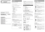
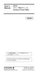
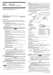
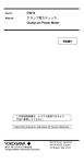
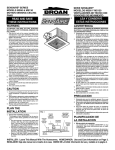
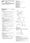
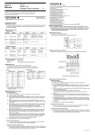
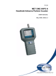
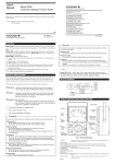
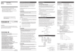
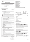
User's
Manual
Components
Safety Precautions
Model 73201/02/03/04
Digital Multimeters
When operating the instrument, be sure to observe the cautionary notes
given below to ensure correct and safe use of the instrument. If you use
the instrument in any way other than as instructed in this manual,
the instrument’s protective measures may be impaired. Yokogawa is by
no means liable for any damage resulting from use of the instrument in
contradiction to these cautionary notes.
WARNING
CAUTION
Indicates a hazard that may result in the loss of life or
serious injury of the user unless the described instruction
is abided by.
Indicates a hazard that may result in an injury to the user
and/or physical damage to the product or other equipment
unless the described instruction is abided by.
The instrument and this manual also use the following safety symbols:
Caution
This symbol indicates that the operator must refer to an explanation
in the instruction manual in order to avoid the risk of injury or death of
personnel or damage to the instrument.
Double Insulation
This symbol indicates double insulation.
Alternating current
This symbol indicates AC voltage/current.
Direct current
This symbol indicates DC voltage/current.
Fuse
This symbol indicates a fuse.
Earth TERMINAL
This symbol indicates ground.
Store this manual in a safe
place for future reference.
WARNING
IM 73201E
7th Edition Dec. 2011(YMI)
Disposing the Product
This Product complies with the WEEE Directive (2002/96/EC) marking
requirement.
The affixed product label (see below) indicates that you must not discard
this electrical/electronic product in domestic household waste.
■ To avoid electric shock!
• Check the testing leads before use and do not use deteriorated or damaged
ones. Check the continuity of the testing leads.
• Do not use the instrument if there is any damage to the casing or when the
casing is removed.
• Disconnect the instrument from the circuit under test before opening the casing
to replace the batteries or for any other reason.
• Avoid using the instrument if it has been exposed to rain or moisture or if your
hands are wet.
Measuring Instructions
1) Function Switch
Turns off the power or selects the measurement mode.
OFF:
Turns off the power.
V:
AC voltage measurement
V:
DC voltage measurement
Ω/
:
Resistance measurement and continuity check (73202/03)
Ω:
Resistance measurement (73201/04)
:
Continuity check (73201/04)
:
Diode test
:
Capacitor check (73202/03)
µA:
DC/AC current measurement in micro-amperes
mA:
DC/AC current measurement in milli-amperes (73201/02/03)
A:
DC/AC current measurement in amperes
2) SELECT key (73202/03) or
/
key (73201)*
This function is not supported on the 73204 multimeter.
This key is enabled only if the multimeter is in one of the following
measurement modes.
• Ω/ :
In this mode, the key selects between the resistance
measurem ent and continuity test.
•
:
In this mode, the key adjusts the stray capacitance of the
testing leads and the multimeter itself to zero.
(The display shows the CAL symbol.)
• µA/mA/A: In this mode, the key selects between the DC and AC modes.
* The 73201 multimeter comes with the / key instead of the SELECT
key. This key is used only to select between the DC and AC modes in the
current measurement mode.
3) RANGE key * This function is not supported on the 73204 multimeter.
Allows the operator to select the measuring range manually (the display
shows the R • H symbol).
To return to the normal auto-ranging mode, hold down this key for at
least one second until the display shows “AUTO.”
4) AUTO-H key
Set up AUTO HOLD function. (the display shows the A • H symbol).
<5> Display
<2> SELECT key (73202/03)
or (
/
= key (73201)
<3> RANGE key
*(2) and (3) are not supported on the
73204 multimeter.
■ To avoid electrical shock or fire!
Do not use the instrument in an atmosphere where any flammable or explosive
gas is present.
CAUTION
To avoid damage to Instrument or equipment.
• Before starting measurement, check to which mode the function switch is set
and make sure the testing leads are plugged into the terminals for the desired
mode of measurement.
• Temporarily remove the testing leads from the device under test before
operating the function switch.
• AC Voltage Measurement (
V
/
4/10
Black testing lead
Red testing lead
• DC Voltage Measurement (
V
/
4/10
Black testing lead
Red testing lead
NOTE
If the 400 mV range is selected and the testing leads are left open-circuited,
the multimeter may give a certain reading. This does not affect your measurement.
• Resistance Measurement (Ω)
CAUTION
To avoid damage to instrument!
Turn off the power to the circuit under test before starting measurement in order
to prevent any excessive voltage from being applied to the multimeter.
<4> AUTO.H key
4/10
With reference to the equipment types in the WEEE directive Annex 1,
this product is classified as a “Monitoring and Control instrumentation”
product.
WARNING
To return unwanted products within the EU area, contact your local
Yokogawa Europe B. V. office. Do not dispose in domestic household waste.
■ To avoid damage to instrument or electric shock!
Measurement Category
Black testing lead
Red testing lead
Input terminal
Maximum Input Voltage
CAT. II
600 V
CAT. III
300 V
Measurement category
For measurements performed on circuits
not directly connected to MAINS.
I
CAT. I
II
CAT. II
For measurements performed on circuits
Appliances, portable
directly connected to the low voltage installation. equipment, etc.
III
CAT. III
For measurements performed
in the building installation.
Distribution board,
circuit breaker, etc.
IV
CAT. IV
For measurements performed at the
source of the low-voltage installation.
Overhead wire, cable
systems, etc.
Internal Wiring
Entrance
Cable
CAT. IV
Distribution
board
5) Display View with All Elements Turned On
Symbol and Unit
A•H
CAT. III CAT. II
T
CAT. I
Fixed Equipment,
etc.
Outlet
Equipment
CAUTION
IM3E-2011.7
• Continuity Check (
)
To avoid damage to instrument!
Remarks
Description
With caps:
1000V 10A CAT.III / 600V 10A CAT.IV
Without caps:
1000V 10A CAT.II / 600V 10A CAT.II
a) Place the function switch in the Ω position (73201/04)
or Ω/ position (73202/03).
b) Plug the black testing lead into the COM input terminal
and the red testing lead into the V•Ω•
input terminal.
c) Connect the testing leads to the circuit under test and
then read the multimeter when it stabilizes.
d) When measurement is complete, place the function
switch in the OFF position and turn off the multimeter.
CAUTION
Category of Testing leads
Yokogawa Meters & Instruments Corporation
International Sales Dept.
Tachihi Bld. No.2, 6-1-3, Sakaecho, Tachikawa-shi,Tokyo 190-8586 Japan
Phone: 81-42-534-1413, Facsimile: 81-42-534-1438
YOKOGAWA CORPORATION OF AMERICA (U.S.A.)
Phone: 1-800-888-6400 Facsimile: 1-770-254-0928
YOKOGAWA EUROPE B. V. (THE NETHERLANDS)
Euroweg 2, 3825 HD, Amersfoort, THE NETHERLANDS
Phone : 31-88-4641000 Facsimile : 31-88-4641111
YOKOGAWA AMERICA DO SUL LTDA. (BRAZIL)
Phone: 55-11-5681-2400 Facsimile: 55-11-5681-4434
YOKOGAWA ENGINEERING ASIA PTE. LTD. (SINGAPORE)
Phone: 65-6241-9933 Facsimile: 65-6241-2606
YOKOGAWA MEASURING INSTRUMENTS KOREA CORPORATION (KOREA)
Phone: 82-2-551-0660 to -0664 Facsimile: 82-2-551-0665
YOKOGAWA AUSTRALIA PTY. LTD. (AUSTRALIA)
Phone: 61-2-8870-1100 Facsimile: 61-2-8870-1111
YOKOGAWA INDIA LTD. (INDIA)
Phone: 91-80-4158-6000 Facsimile: 91-80-2852-1441
YOKOGAWA SHANGHAI TRADING CO., LTD. (CHINA)
Phone: 86-21-6239-6363 Facsimile: 86-21-6880-4987
YOKOGAWA MIDDLE EAST B. S. C (C) (BAHRAIN)
Phone: 973-17-358100 Facsimile: 973-17-336100
YOKOGAWA ELECTRIC CIS LTD. (RUSSIAN FEDERATION)
Phone: 7-495-737-7868 Facsimile: 7-495-737-7869
<1> Function switch
The restrictions on the maximum voltage level for which the 73201, 02, 03 and
04 multimeters can be used, depend on the measurement categories specified
by the safety standards. These category specifications are formulated to protect
operators against transient impulse voltages in power lines.
V)
a) Set the function switch from the OFF position to the
V position.
b) Plug the black testing lead into the COM input terminal
and the red testing lead into the V•Ω•
input terminal.
c) Connect the testing leads to the circuit under test
and then read the multimeter when it stabilizes.
d) When measurement is complete, set the function switch
back to the OFF position and turn off the multimeter.
Do not mistake the following for a malfunction!
/
Product Category
V)
a) Set the function switch from the OFF position to the
V position.
b) Plug the black testing lead into the COM input termi nal and the red testing lead into the V•Ω•
input
terminal.
c) Connect the testing leads to the circuit under test
and then read the multimeter when it stabilizes.
d) When measurement is complete, set the function switch
back to the OFF position and turn off the multimeter.
• Do not use the multimeter near noise-emitting equipment or where there may
be a sudden temperature change. Otherwise, the instrument may produce an
unstable reading or errors.
• Do not wipe the instrument using any solvent (chemicals) such as benzine or
paint thinner. Otherwise, the front panel may be damaged or discolored.
When cleaning the instrument, use a dry cloth.
• Do not leave the multimeter exposed to direct sunlight or in a hot and humid
location such as the inside of a car, for any prolonged length of time.
R•H
AUTO
AUTO POWER OFF
nF, µF
mV, V
µA, mA, A
Ω, kΩ, ΜΩ
CAL
+–
Turn off the power to the circuit under test before starting measurement in order
to prevent any excessive voltage from being applied to the multimeter.
Description
Lit when in DC-mode measurement
Lit when in AC-mode measurement
Polarity indicator lit when the polarity is negative
Lit when in diode test
Lit when in continuity check
AUTO HOLD indicator
Manual range indicator
Auto range indicator
AUTO POWER OFF indicator
Unit for capacitance measurement
Unit for voltage measurement
Unit for current measurement
Unit for resistance measurement
Lit when stray capacitance is adjusted to zero
Lit when the batteries are low
/
4/10
Black testing lead
Red testing lead
a) If the model is 73201 or 04, place the function switch
in the position.
If the model is 73202 or 03, place the function switch
in the Ω / position, and then press the SELECT key.
(The symbol appears on the display.)
b) Plug the black testing lead into the COM input terminal
input terminal.
and the red testing lead into the V•Ω•
c) Connect the testing leads to the circuit under check.
If the circuit is continuous (no more than approximately
50 Ω), the buzzer sounds.
d) When the test is complete, place the function switch in
the OFF position and turn off the multimeter.
• Diode Test ( )
a) Set the function switch from the OFF position to the
position.
b) Plug the black testing lead into the COM input terminal
and the red testing lead into the V•Ω• input terminal.
c) Connect the testing leads to the diode and then read
the multimeter when it stabilizes.
/
4/10
(1) Forward-bias Diode Test
Connect the black testing lead to the cathode and
the red testing lead to the anode (see Figure 1).
Silicon diodes should give a reading of approxiBlack testing Red testing mately 0.5 V and light-emitting diodes a reading
lead
lead
between 1.5 V and 2.0 V. Note that readings
close to 0 V represent a short-circuit and the "---"
symbol indicates an opencircuit.
(2) Reverse-bias Diode Test
Connect the black testing lead to the anode and
the red testing lead to the cathode (see Figure 2).
Figure 1 Forward-bias
Normally, the display shows the "---" symbol,
Diode Test
indicating that the diode under test is normal.
Red testing Black testing
The diode is defective if the display gives a
lead
lead
certain voltage level.
Black testing lead
Red testing lead
d) When the test is complete, set the function switch
back to the OFF position and turn off the multimeter.
Figure 2 Reverse-bias
Diode Test
• Capacitor Check ( )
*This function is not supported on the 73201/04 multimeters.
CAUTION
To avoid damage to Instrument or equipment.
Before starting measurement, be sure to discharge the capacitor under check.
/
4/10
Red
testing lead
Black testing lead
NOTE
a) Set the function switch from the OFF position to the
position.
b) Plug the black testing lead into the COM input terminal
and the red testing lead into the μA • mA • input
terminal.
c) Press the SELECT key to adjust the stray capacitance
CAL symbol).
to zero (thedisplay shows the CAL
d) Connect the testing leads to the circuit under check
and then read the multimeter when it stabilizes.
e) When measurement is complete, set the function
switch back to the OFF position and turn off the
multimeter.
AUTO HOLD Function
The 732 series of multimeters can automatically retain the measured
value when the testing leads are handled as described below.
a) Press the AUTO.H key. (The display shows the A • H symbol.)
b) Connect the testing leads to the object under test.
c) When the reading stabilizes, the buzzer sounds.
d) Remove the testing leads from the object under test.
e) The multimeter now shows the measured value that it retains.
f) You can repeat steps b) to e) as many times as you like as long as the
display shows the A • H symbol.
NOTE
Do not mistake the following for a malfunction!
• In DC voltage measurement, the AUTO HOLD function is only available for
ranges greater than the 4 V range.
• This function is not available for current-mode measurement.
• In a capacitor check, the AUTO HOLD function requires a few seconds before
it takes effect.
• The AUTO HOLD function cannot be applied to unstable signals.
g) To cancel this function, press the
CAUTION
To avoid damage to instrument!
• Check to which mode the function dial is set before starting measurement.
• A current of 11 to 20 A can also be measured if the time interval is kept within
30 seconds. The buzzer will sound if the interval exceeds 30 seconds. If this
happens, immediately stop measurement. To continue measurement, wait for
2 minutes or more when restart.
a) Set the function switch from the OFF position to either the μA, mA or A
position. (If the magnitude of the current being measured is not known,
select the A position.)
b) When measuring AC current, press the SELECT key to select the AC
mode. (The display shows the “ ” symbol to indicate AC-mode
measurement.)
c) Plug the black testing lead into the COM input terminal and the red testing
lead into the A input terminal. If the current is in the order of milli-amperes
or less, plug the red testing lead into the μA•mA• input terminal.
d) Connect the testing leads to the circuit under test and then read the
multimeter when it stabilizes.
e) When measurement is complete, set the function switch back to the
OFF position and turn off the multimeter.
mA
mA
/
4/10
Red testing lead
Black testing lead
A
A
/
4/10
Red testing lead
Black testing lead
key once again.
The multimeter automatically turns off if no key is pressed for a period of
20 minutes. The multimeter will beep for approximately one minute to alert
the operator before the automatic power-off function takes effect.
(Pressing any key while the multimeter is beeping postpones the power-off
time. Pressing any key once after the power to the multimeter is automatically turned off switches the multimeter on again.)
To cancel the automatic power-off function, hold down the SELECT key
and then set the function switch from the OFF to the position of any
desired measurement mode. (The AUTO POWER OFF indication turns off
when the function is canceled.)
To enable the function once again, temporarily switch the function switch
back to the OFF position, and then select the desired measurement mode.
Battery Replacement
If the batteries fall below the normal operating voltage, the
symbol
turns on. If this happens, replace the batteries with new ones (AAA-size
[ANSI] batteries: 2pcs.).
CAUTION
To avoid electric shock!
• Be sure to disconnect the multimeter from the circuit under test before replacing
the batteries.
• Replace both batteries at the same time making sure to position them with the
correct polarities.
Zero calibration is only effective when the 20nF range is selected.
• Current Measurement (μA/mA/A)
*This fucntion is not supported on the 73204 multimeter.
A•H
AUTO POWER OFF Function
Do not mistake the following for a malfunction!
• AC Current Measurement ( A)
* This function is not supported on the 73204 multimeter.
Specifications
To replace the batteries:
Remove the three screws on the back of the casing.
Open the casing.
Take the battery holder out of the casing.
Replace the batteries with new ones and install the
battery holder back into the casing.
e) Close the casing and fasten it with the three screws.
b)
a)
b)
c)
d)
c)
1. General Specifications
Fuse Replacement
If a current greater than the rated value flows when the multimeter is in the
current-measurement range, a protection fuse may blow. If this happens,
replace that fuse. The multimeter contains the following two types of fuses:
• Type F05 250 V/500 mA fuse
• Type F02 250 V/15 A fuse
CAUTION
To avoid electric shock!
• Be sure to disconnect the multimeter from the circuit under test before replacing
the fuse(s).
• Do not operate the multimeter with the casing left open.
• In order to avoid damage to the multimeter or any possible accident, use fuses
of the specified rating.
To replace the fuse(s):
a) Remove the three screws on the back of the casing.
b) Open the casing.
c) Remove the blown fuse from the fuse holder.
d) Install a new fuse in the holder.
F02:15 A/250 V
protection fuse
e) Close the casing and fasten it with the
F05:500 mA/250 V
three screws.
protection fuse
View with the Casing Open
4000 μA
Accuracy (40-500 Hz)
Resolution
73201
73202 73203
0.1 μA
2% + 20
1 μA
2% + 5
mA
40 mA*2
0.01 mA
A
400 mA
10 A*3
0.1 mA
0.01 A
Range
400 μA*1
µA
Voltage
Drop
Maximum
Input Current
400 mA
The input
is protected by a
500mA/250 V fuse
<0.17 mV/μA
2% + 20
2% + 5
2.5% + 20
<3 mV/mA
10 A
The input is
protected by a
15 A/250 V fuse
<0.04 V/A
*1, *2 These ranges may produce a readout error equivalent to several times their resolution.
*3
A current of 11 to 20 A can also be measured if the time interval is kept within 30 seconds.
The buzzer will sound if the interval exceeds 30 seconds.
Response: 2 sec maximum
• Resistance Measurement (Ω)
Resolution
Range
400 Ω
0.1 Ω
4 kΩ
0.001 kΩ
Accuracy
73201/02/03/04
0.75%+2
0.75%+1
Measuring
Current
Open-loop
Voltage
Input Protective
Voltage
<1.0 mA
<3.4 V
600 V
<0.5 mA
<1.0 V
<0.7 V
40 kΩ
0.01 kΩ
<70 μA
400 kΩ
0.1 kΩ
<7 μA
4 MΩ
0.001 MΩ
2%+1
40 MΩ
0.01 MΩ
5%+2
Response:
<0.7 μA
<70 nA
1 sec maximum for ranges lower than the 400 kΩ range, 5 sec maximum for the
4 MΩ range, and 15 sec maximum for the 40 MΩ range
• Continuity check (
Range
)
Range of operation
Resolution
Open-circuit
Voltage
73201/02/03/04
400 Ω
0.1 Ω
The buzzer turns on for
resistances lower than 50 ±20 Ω.
Input Protective
Voltage
<3.4 V
600 V
Open-circuit
Voltage
Input Protective
Voltage
<3.4 V
600 V
Response: 0.2 sec maximum (for a buzzer response)
• Diode Test (
Range
2V
)
Resolution
Accuracy
0.01 V
73201/02/03/04
1% + 1 (for measuring currents
smaller than 1.0 mA)
Response: 1 sec maximum
• Capacitor check (
Range
Resolution
)
20 nF
0.01 nF
200 nF
0.1 nF
2 μF
0.001 μF
20 μF
0.01 μF
200 μF
0.1 μF
Protection Fuse
Accuracy
73201/04
73202
73203
This function 2% + 5 typical
is not
Readings in the 20nF
available.
range are values after zero
calibration has been
completed.
By means of a
500 mA/250 V fuse
2. Accuracy (Electrical Specification)
Test conditions: 23 ±5°C at 80% RH maximum
Accuracy:
±(percentage of reading + number of LSD reading)
Note:
Each response noted below is a value measured in the
Range Hold mode (manual range setting).
Response: 1 sec maximum
• DC Voltage Measurement (
This User’s Manual explains the Prevention of Pollution Control of
Electronic Equipment Method in China. This manual is valid only in China.
Range
a)
(Mean-value detection and rms-value calibration)
• Measurement functions: AC voltage, DC voltage, AC current
(73201/02/03), DC current (73201/02/03),
resistance, continuity, diode and capacitance
(73202/03)
Auto hold, manual range selection, over-range
• Additional functions:
alarm, and Auto power off.
• Display:
LCD display that is capable of indicating a
significant reading of up to 4300 counts along
with the indications of the unit and function. It
shows the negative polarity only; no indication is
given for positive polarity. The display also has
the OL or over-range and
lowbattery alarm
indicators.
Note: The most significant reading is 210 counts
for the diode test and 2300 counts for the
capacitor check.
• Range selection:
Manual or automatic
• Sampling:
2 times/sec
• Operating temperature and humidity ranges:
0 to 50°C (Accuracy guaranteed range: 23±5°C)
Where the range is 0 to 40°C for humidity of
80%RH or less and 40 to 50°C for humidity of
70%RH or less
• Storage temperature and humidity ranges:
-20°C to 60°C; 70% RH maximum
• Battery life:
Approximately 600 hours (when continuously
operated on alkaline batteries)
AAA-size batteries (ANSI) .........................2pcs.
• Power supply:
• External dimensions:
Approx.74 (W) × 155 (H) × 31 (D) mm
(excluding protrusions)
• Weight:
Approx. 240 g (including batteries)
EN 61010-1, EN 61010-031
• Safety standards:
(AC/DC 300V CAT.III, AC/DC 600 V CAT. II,
Pollution degree2) Operable altitude : 2000m
max above sea level, Indoor use
• EMC standards:
EN 55011 Group 1 Class B
EN 61326-1, EN 61326-2-2
• Effect of EMS immunity: Accuracy range of reading: (Rated accuracy of
each range) ×5 for the strength of a radiofrequency electromagnetic field of 3 V/m
• Accessories:
Batteries (housed in the instrument) ..........2pcs.
Testing leads..............................................1set
Spare fuse: F05 (500 mA/250 V) ................1
F02 (15 A/250 V) .....................1
User’s manual ..........................................1
V)
Accuracy
73202/04
Resolution
Input
Resistance
Maximum
Input Voltage
73201
73203
400 mV
0.1 mV
0.5%+1
>100MΩ
600 V
4V
0.001 V
11MΩ
0.5%+1
0.3%+ 1
40 V
0.01 V
10M Ω
0.1 V
400 V
0.75%+1
1V
600 V
Response: 1.5 sec maximum for 400 mV range or 1 sec maximum for other ranges
• AC Voltage Measurement (
Range
Resolution
4V
0.001 V
40 V
0.01 V
400 V
0.1 V
600 V
1V
Response: 2 sec maximum
V ) (Mean-value detection and rms-value calibration)
Accuracy (40-500 Hz)
73201
73202 73203/04
1%+5
0.75%+5
Input
Resistance
Maximum
Input Voltage
11 MΩ, <50 pF
10 MΩ, <50 pF
600 V
μA
mA
A
400 μA*1
4000 μA
40 mA*2
400 mA
10 A*3
Resolution
0.1 μA
1 μA
0.01 mA
0.1 mA
0.01 A
产品中有毒有害物质或元素的名称及含量
有毒有害物质
部件名称
铅
(Pb)
汞
(Hg)
镉
(Cd)
六价铬
(Cr (VI))
多溴联苯
(PBB)
多溴二苯醚
(PBDE)
框架(塑料)
×
×
×
×
○
○
线路板 ASSY
×
×
×
×
○
○
导线
×
×
×
×
○
○
电池
×
×
×
×
○
○
○:表示该部件的所有均质材料中的有毒有害物质的含量均在 SJ/T11363-2006 标准中所规定的限量
以下
×:表示该部件中至少有一种均质材料中的有毒有害物质或元素的含量超过 SJ/T11363-2006 标准所规
定的限量要求。
环保使用期限 :
• DC Current Measurement ( A)
* This function is not supported on the 73204 multimeter.
Range
"Measures for Administration of the Pollution Control of
Electronic Information Products" of the People's
Republic of China
73201
Accuracy
73202 73203
1% + 2
2% + 2
Voltage
Drop
Maximum
Input Current
<0.17 mV/μA
400 mA
The input is
protected by a
500 mA /250 V fuse
<3 mV/mA
<0.04 V/A
10 A The input is
protected by a
15 A /250 V fuse
*1, *2 These ranges may produce a readout error equivalent to several times their resolution.
*3
A current of 11 to 20 A can also be measured if the time interval is kept within 30
seconds. The buzzer will sound if the interval exceeds 30 seconds.
Response: 1 sec maximum
该标识适用于 2006 年 2 月 28 日颁布的《电子信息产品污染控制管理办法》
以及SJ /T11364 – 2006《电子信息产品污染控制标识要求》中所述, 在中华人民
共和国销售的电子信息产品的环保使用期限。
只要您遵守该产品相关的安全及使用注意事项,在自制造日起算的年限内,则不
会因产品中有害物质泄漏或突发变异, 而造成对环境的污染或对人体及财产产生
恶劣影响。
注)该年数为“环保使用期限"
,并非产品的质量保证期。零件更换的推荐周期,
请参照使用说明书。
IM 73201E <P2>