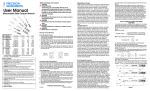
1
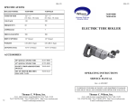
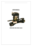
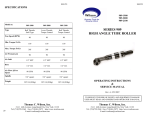
SM-121A
SM-121A
SPECIFICATIONS
1041-1601
Model no.
Free Speed (RPM)
Air Pressure psi
Air Inlet
1041-1601
12000
90
1/4” NPT
3/8” I.D. Minimum
Hose
Air Flow @Free Speed
Spindle
HANDHOLE SEAT GRINDER
22 CFM
3/8”-24 UNF-2
OPERATING INSTRUCTIONS
&
SERVICE MANUAL
Rev: A, 9/17/2007
TO REDUCE THE RISK OF INJURY AND EQUIPMENT DAMAGE
USER MUST READ AND UNDERSTAND OPERATOR’S MANUAL.
12
Thomas C. Wilson, Inc.
Thomas C. Wilson, Inc.
21-11 44th Avenue, Long Island City, New York 11101
Tel: (718)729-3360 Fax: (718)361-2872 http://www.tcwilson.com
E-mail: [email protected]
21-11 44th Avenue, Long Island City, New York 11101
Tel: (718)729-3360 Fax: (718)361-2872 http://www.tcwilson.com
E-mail: [email protected]
SM-121A
SAFETY INSTRUCTIONS
!
WARNING!
READ AND UNDERSTAND ALL INSTRUCTIONS
Failure to follow all instructions listed below, may result
in accident, fire and/or personal injury.
SAVE THESE INSTRUCTIONS
SM-121A
SELECTION CHART
FOR GUIDE ROLLER AND WHEEL
Grinding Wheel
Seat Width
Inch
MM
3/16
4.8
7/32
5.6
Dia. (in)
2
Coarse Grit
Fine Grit
Cat. No
Cat No.
1041-0029
1041-1029
Guide Roll
Dia.(in)
Cat. No.
1-5/8
1041-0025
1-9/16
1041-0026
1-1/2
1041-0027
Do not allow corrosive gases or foreign material to enter the unit. Moisture, oilbased contaminants, or other liquids must be filtered out.
1/4
6.4
9/32
7.1
1-7/16
1041-0028
2.
Eye protection is always required when running motor.
5/16
7.9
1-5/8
1041-0025
3.
Hearing protection is recommended when in close proximity to all operating air
motors.
11/32
8.7
1-9/16
1041-0026
3/8
9.5
1-1/2
1041-0027
13/32
10.3
1-7/16
1041-0028
7/16
11.1
1-5/8
1041-0025
15/32
11.9
1-9/16
1041-0026
1/2
12.7
1-1/2
1041-0027
17/32
13.5
1-7/16
1041-0028
1-5/8
1041-0025
1-9/16
1041-0026
1-1/2
1041-0027
1-7/16
1041-0028
1.
4.
5.
Dust mask, non-skid safety shoes, hard hat, gloves and other personal safety equipment must be used.
Stay alert, watch what you are doing, and use common sense when operating a
power tool.
6.
Dress properly. Do not wear loose clothing or jewelry.
7.
Keep your work area clean and well lit.
9/16
14.3
8.
Do not operate power tools in explosive atmospheres, such as in the presence of
flammable liquids, gases, or dust.
19/32
15.1
5/8
15.9
Disconnect the tool from the air supply before installing, making any adjustment,
changing accessories, servicing or storing tool.
21/32
16.7
9.
2-1/4
2-1/2
2-3/4
1041-0081
1041-0082
1041-0083
1041-1081
1041-1082
1041-1083
Caution: Be sure that the wheel being used with the grinder complies with
the requirements established in the American Standard Safety Code for “The
use, Care and Protection of Abrasive Wheels” A.S.A. B7.1-1964
2
11
SM-121A
SM-121A
MAINTENANCE
GUIDELINES
Rotor Blades
The Wilson Pneumatic Handhole Seat Grinder will restore to a smooth, flat surface
the gasket seat of any size or shape of handhole. Corroded, pitted, dented,
scratched, fluid-abraded seats can be returned to perfect sealing condition with this
tool. The Wilson grinder is a precision tool, ruggedly built for long usefulness under rough working conditions.
Replace if broken or worn 1/16” below slot top.
Rotor Spindle
A dropped tool may have a bent spindle. Check for straightness and replace if necessary.
Cylinder and Rear End Plate
Replace if surface is gouged or pitted from rust or moisture.
Ball Bearing
Clean dirty ball bearings in kerosene and flush with clean light oil (SAE10). All ball
bearings should turn smoothly and freely with no noticeable looseness.
Air Screen
Clean air screen in Bushing (key 49) by reverse flushing.
Caution Rust
Before storing tool, put a good amount of oil into motor.
Disassembly
1.
2.
3.
Unscrew Motor Housing (key 32) from Throttle Housing (key 48).
Push out Rotor Assembly (key 33) to 44).
Pull Rear Plate Assembly (key40 to 44) off rotor, freeing cylinder and blades.
Disassemble above only for parts replacement.
Reassembly
Follow above steps in reverse.
10
The grinder assembly is mounted by attachment to the handhole plate stud of a
nearby handhole. Then the assembly is leveled by adjusting the leveling screws
with the motor assembly attached so that the grinding wheel is in the handhole. The
motor is positioned up or down as required for the grinding wheel to take the desired cut from the existing seat. Then the motor is turned on and moved about the
hole while the guide roller bears against the side of the handhole and the new seat is
ground.
Removal of one screw permits taking the motor and wheel out of the handhole for
examination of the seat. (An accessory inspection mirror is furnished to facilitate
this.) The wheel can then be replaced in the hole without disturbing the setting.
The rugged bracket which supports the powerful grinder motor moves in dovetail
ways to insure precise alignment and is clamped to prevent any deviation from the
height setting made by turning the adjusting handle.
Alternate mounting locations are provided for attaching the motor clamp to the
dovetail slide when the handhole is in a header of 1-1/2" to 2-1/2" thickness.
The grinder can reach 12-5/8 inches from the mounting stud to the far side of the
handhole with a 2" dia. wheel attached. If a greater reach is needed, an accessory 5"
long extension can be inserted between the motor clamp and slide bracket. Still
greater reaches can be accommodated by the use of an extension mounting bar.
Various seat widths can be ground by selecting the proper combinations of guide
rollers and wheel diameters. For extra large handholes, an additional extension link
attached, will accommodate for the increased contour to be ground.
A cup brush may substitute for the grinding wheel if grinding is not needed and
cleaning of the seat will suffice. The motor can be used for free-hand wire brushing
by unbolting the clamp from the slide. Wear eye protection.
3
SM-121A
SM-121A
HOSES
Attach hose whip supplied with Filter Lubricator No. 8596 to air motor.
LUBRICATION
Air motors are lubricated with oil laden operating air. Use S.A.E. No. 10 oil or
`Wilsolube" Pneumatic Motor Oil No. 9047 in the Wilson Filter-Lubricator No. 8596.
Check that a fine mist of oil is always present in exhaust air. Keep hinges, dovetail,
guide roller and screw threads coated with light oil.
EQUIPMENT SELECTION
1. Measure handhole seat width. Select and attach guide roller to motor. See chart
on last page. Note that Roller Retainer (Key 30) has a left- hand thread, Be sure both
blotters are between Flanges (Key 28 & 29) when mounting grinding wheel.
2. Mount grinder on plate stud of one handhole while grinding the seat of another.
The long Mounting Nut (Key 2) has a l"-8 thread. For a handhole stud with a 7/8"-9
thread, use Adapter No. 1041-0035. For a 3/4"-lO thread, use No. 1041-0036.
OPERATION
RECOMMENDED OPERATING AIR PRESSURE 90 PSI
1. To avoid damage to the grinding wheel, temporarily remove Motor Assembly
(No, 1041-0088) from Slide Assembly (Key 8). Unscrew Cap Screw (Key 26)
with washer.
2. Attach mounting assembly (No. 1041-3067) to the handhole plate stud with
Mounting Nut (key 2) in the general direction of the seat to be ground.
3. Place motor assembly in the handhole and bolt its clamp with cap screw and washer
to Slide Bracket (key 23).
4. Position grinding wheel by turning Handle (key 9). Lock assembly against movement. Alternately set the (4) Leveling Screws (key3) and the slide height to position
the grinding wheel squarely to the existing handhole seat.
5. For a light cut, turn on motor and adjust slide handle. Move motor until guide roller
touches handhole side. Then, with the roller in contact with hole wall, move the
motor around hole. Graduations on micrometer thimble are in thousands of an inch.
6. Avoid a rapid breakdown of the grinding wheel face, by taking a series of light
cuts.
7. Unbolt motor to examine seat surface with inspection mirror (No. 1041-0030).
4
ACCESSORIES
This can be useful for extra long reach
or to avoid obstructions. The nut, at one
end, is to be screwed onto a handhole
plate stud. The grinder mounting assembly is then attached to the bar screw
which may be placed in any of the four
3-3/8” spaced holes. (13-1/2” max.) A
screw within the bar screw provides
support for added rigidity.
EXTENSION LINK 1041-0065
For extra large handhole, an additional extension
link attached will accommodate for the increased
contour to be ground.
Simply attach extension link between link (key7)
and dovetail body (key 22). For a flawless reassembly leave link pins (key 5) in their prior location.
INDICTOR CLAMP 1041-0087
Additional convenience can be secured by using a
separate Indicator Clamp Assembly., so that the
motor does not have to be moved in and out of the
motor clamp.
ALIGNMENT INDICATOR 1043
This device greatly facilitates set-up. It is mounted in
place of the motor. The serrations shown are on a blade
which is brought into contact with the wall of the handhole. A pointer attached to the blade indicates the alignment of the mounting with respect to the hole. If the
equipment is leveled to align with the hole wall, the subsequent grinding cut will be square with the hole.
9
SM-121A
PARTS LIST
Key Description
8
KIT LIST
Part No.
Key Description
Part No.
DESCRIPTION
QTY.
CAT. NO.
TOOL BOX
1
24939-0000
HANDHOLE SEAT GRINDER ASS’Y
1
1041-1600
MOTOR ASSEMBLY WITH CLAMP
1
1041-0088
1041-0022
MOUNTING ASSEMBLY
1
1041-3067
1041-0021
HOSE WHIP (8' LONG - 3/8 I.D.)
1
50371-0000
24525
EXTENSION ARM ASSEMBLY
1
104 1-0093
1041-0020
CUP BRUSH, 2" DIA.
1
8340-0000
1041-0023
GRINDING WHEEL, 2" (COARSE GRIT) 1
1041-0029
GRINDING WHEEL, 2" (FINE GRIT)
1
1041-1029
GUIDE ROLLER (1-5/8" DIA.)
1
1041-0025
GUIDE ROLLER (1-9/16" DIA.)
1
1041-0026
GUIDE ROLLER (1-1/2" DIA.)
1
1041-0027
50817-0004
GUIDE ROLLER (1-7/16" DIA.)
1
1041-0028
52496
NP ADAPTER (1"-8M X 7/8-9F)
1
1041-0035
NP ADAPTER (1"-8M X 3/4-1OF)
1
1041-0036
5/16" HEX. KEY
1
52147-0000
3/16" HEX. KEY
1
51254-0000
5/64" HEX. KEY
1
52142-0000
Handhole Seat Grinder
1041-1600
Motor & Clamp Assembly
1041-0088
Mounting Assembly
1041-3067
Motor &Throttle Housing
1041-1900
1
Leveling Plate
1041-0003
27
Hex Nut
50455
2
Mounting Nut
1041-0002
28
Front Flange
50807
3
Cap Screw
1041-0063
29
Rear Flange
4
Leveling Bracket
1041-0004
30
Retainer
5
Link Pin (4)
1041-0006
31
Ball Bearing
6
Roll Pin (4)
28056
32
Motor Housing
7
Link
1041-0005
33
Spindle—4 slots
8
Slide Assembly
1041-3059
34
Front Bearing Nut
50812
9
Handle
1041-3051
35
Ball Bearing
50827
10
Roll Pin
28062
36
Front Spacer
50810
11
Set screw
40015
37
Front Plate
50809
12
Micrometer Dial
1041-3052
38
Cylinder
50816
13
Washer
1041-0055
39
Rotor Blades (set of 4)
Index Plate Assembly
1041-3049
40
Pin
14
Index Plate
SM-121A
1041-3149
41
Rear Plate
52978-0014
15
Bearing Sleeve
1041-3057
42
Ball Bearing
24520
16
Washer
1041-3102
43
Nameplate
52152
17
Lead Screw
1041-3150
44
Rear Plate Plug
53071
18
Button Head Screw (2)
1041-3039
19
Hex Nut (2)
1041-3141
20
Front Flange (2)
21
Throttle Assembly
1041-0069
45
Push Button ‘ON’
50895
WRENCH, 9/16" X 7/16"
1
1041-0072
1041-3041
46
O-Ring
7830
WHEEL DRESSING STONE
1
1041-0066
Rear Flange (2)
1041-3241
47
Push Button ‘OFF’
50893
INSPECTION MIRROR
1
1041-0030
22
Dovetail Body
1041-3038
48
Throttle Housing
FILTER-LUBRICATOR ASSEMBLY
1
8596-0000
23
Slide Bracket
1041-3046
49
Bushing with Screen
AIR LINE FILTER
1
8911-0000
HEX. NIPPLE - BRASS
1
9360-0000
AIR LINE LUBRICATOR
1
3611-0000
24
Gib
25
Washer
30574
26
Cap Screw
24004
1041-0096
53629
Motor Clamp Assembly
1041-0087
50
Motor Clamp
1041-0086
51
Cap Screw
1006-0010
52
Gasket
1041-0060
1041-3040
5
SM-121A
SM-121A
PARTS LIST
6
7
SM-121A
SM-121A
PARTS LIST
6
7
SM-121A
PARTS LIST
Key Description
8
KIT LIST
Part No.
Key Description
Part No.
DESCRIPTION
QTY.
CAT. NO.
TOOL BOX
1
24939-0000
HANDHOLE SEAT GRINDER ASS’Y
1
1041-1600
MOTOR ASSEMBLY WITH CLAMP
1
1041-0088
1041-0022
MOUNTING ASSEMBLY
1
1041-3067
1041-0021
HOSE WHIP (8' LONG - 3/8 I.D.)
1
50371-0000
24525
EXTENSION ARM ASSEMBLY
1
104 1-0093
1041-0020
CUP BRUSH, 2" DIA.
1
8340-0000
1041-0023
GRINDING WHEEL, 2" (COARSE GRIT) 1
1041-0029
GRINDING WHEEL, 2" (FINE GRIT)
1
1041-1029
GUIDE ROLLER (1-5/8" DIA.)
1
1041-0025
GUIDE ROLLER (1-9/16" DIA.)
1
1041-0026
GUIDE ROLLER (1-1/2" DIA.)
1
1041-0027
50817-0004
GUIDE ROLLER (1-7/16" DIA.)
1
1041-0028
52496
NP ADAPTER (1"-8M X 7/8-9F)
1
1041-0035
NP ADAPTER (1"-8M X 3/4-1OF)
1
1041-0036
5/16" HEX. KEY
1
52147-0000
3/16" HEX. KEY
1
51254-0000
5/64" HEX. KEY
1
52142-0000
Handhole Seat Grinder
1041-1600
Motor & Clamp Assembly
1041-0088
Mounting Assembly
1041-3067
Motor &Throttle Housing
1041-1900
1
Leveling Plate
1041-0003
27
Hex Nut
50455
2
Mounting Nut
1041-0002
28
Front Flange
50807
3
Cap Screw
1041-0063
29
Rear Flange
4
Leveling Bracket
1041-0004
30
Retainer
5
Link Pin (4)
1041-0006
31
Ball Bearing
6
Roll Pin (4)
28056
32
Motor Housing
7
Link
1041-0005
33
Spindle—4 slots
8
Slide Assembly
1041-3059
34
Front Bearing Nut
50812
9
Handle
1041-3051
35
Ball Bearing
50827
10
Roll Pin
28062
36
Front Spacer
50810
11
Set screw
40015
37
Front Plate
50809
12
Micrometer Dial
1041-3052
38
Cylinder
50816
13
Washer
1041-0055
39
Rotor Blades (set of 4)
Index Plate Assembly
1041-3049
40
Pin
14
Index Plate
SM-121A
1041-3149
41
Rear Plate
52978-0014
15
Bearing Sleeve
1041-3057
42
Ball Bearing
24520
16
Washer
1041-3102
43
Nameplate
52152
17
Lead Screw
1041-3150
44
Rear Plate Plug
53071
18
Button Head Screw (2)
1041-3039
19
Hex Nut (2)
1041-3141
20
Front Flange (2)
21
Throttle Assembly
1041-0069
45
Push Button ‘ON’
50895
WRENCH, 9/16" X 7/16"
1
1041-0072
1041-3041
46
O-Ring
7830
WHEEL DRESSING STONE
1
1041-0066
Rear Flange (2)
1041-3241
47
Push Button ‘OFF’
50893
INSPECTION MIRROR
1
1041-0030
22
Dovetail Body
1041-3038
48
Throttle Housing
FILTER-LUBRICATOR ASSEMBLY
1
8596-0000
23
Slide Bracket
1041-3046
49
Bushing with Screen
AIR LINE FILTER
1
8911-0000
HEX. NIPPLE - BRASS
1
9360-0000
AIR LINE LUBRICATOR
1
3611-0000
24
Gib
25
Washer
30574
26
Cap Screw
24004
1041-0096
53629
Motor Clamp Assembly
1041-0087
50
Motor Clamp
1041-0086
51
Cap Screw
1006-0010
52
Gasket
1041-0060
1041-3040
5
SM-121A
SM-121A
HOSES
Attach hose whip supplied with Filter Lubricator No. 8596 to air motor.
LUBRICATION
Air motors are lubricated with oil laden operating air. Use S.A.E. No. 10 oil or
`Wilsolube" Pneumatic Motor Oil No. 9047 in the Wilson Filter-Lubricator No. 8596.
Check that a fine mist of oil is always present in exhaust air. Keep hinges, dovetail,
guide roller and screw threads coated with light oil.
EQUIPMENT SELECTION
1. Measure handhole seat width. Select and attach guide roller to motor. See chart
on last page. Note that Roller Retainer (Key 30) has a left- hand thread, Be sure both
blotters are between Flanges (Key 28 & 29) when mounting grinding wheel.
2. Mount grinder on plate stud of one handhole while grinding the seat of another.
The long Mounting Nut (Key 2) has a l"-8 thread. For a handhole stud with a 7/8"-9
thread, use Adapter No. 1041-0035. For a 3/4"-lO thread, use No. 1041-0036.
OPERATION
RECOMMENDED OPERATING AIR PRESSURE 90 PSI
1. To avoid damage to the grinding wheel, temporarily remove Motor Assembly
(No, 1041-0088) from Slide Assembly (Key 8). Unscrew Cap Screw (Key 26)
with washer.
2. Attach mounting assembly (No. 1041-3067) to the handhole plate stud with
Mounting Nut (key 2) in the general direction of the seat to be ground.
3. Place motor assembly in the handhole and bolt its clamp with cap screw and washer
to Slide Bracket (key 23).
4. Position grinding wheel by turning Handle (key 9). Lock assembly against movement. Alternately set the (4) Leveling Screws (key3) and the slide height to position
the grinding wheel squarely to the existing handhole seat.
5. For a light cut, turn on motor and adjust slide handle. Move motor until guide roller
touches handhole side. Then, with the roller in contact with hole wall, move the
motor around hole. Graduations on micrometer thimble are in thousands of an inch.
6. Avoid a rapid breakdown of the grinding wheel face, by taking a series of light
cuts.
7. Unbolt motor to examine seat surface with inspection mirror (No. 1041-0030).
4
ACCESSORIES
This can be useful for extra long reach
or to avoid obstructions. The nut, at one
end, is to be screwed onto a handhole
plate stud. The grinder mounting assembly is then attached to the bar screw
which may be placed in any of the four
3-3/8” spaced holes. (13-1/2” max.) A
screw within the bar screw provides
support for added rigidity.
EXTENSION LINK 1041-0065
For extra large handhole, an additional extension
link attached will accommodate for the increased
contour to be ground.
Simply attach extension link between link (key7)
and dovetail body (key 22). For a flawless reassembly leave link pins (key 5) in their prior location.
INDICTOR CLAMP 1041-0087
Additional convenience can be secured by using a
separate Indicator Clamp Assembly., so that the
motor does not have to be moved in and out of the
motor clamp.
ALIGNMENT INDICATOR 1043
This device greatly facilitates set-up. It is mounted in
place of the motor. The serrations shown are on a blade
which is brought into contact with the wall of the handhole. A pointer attached to the blade indicates the alignment of the mounting with respect to the hole. If the
equipment is leveled to align with the hole wall, the subsequent grinding cut will be square with the hole.
9
SM-121A
SM-121A
MAINTENANCE
GUIDELINES
Rotor Blades
The Wilson Pneumatic Handhole Seat Grinder will restore to a smooth, flat surface
the gasket seat of any size or shape of handhole. Corroded, pitted, dented,
scratched, fluid-abraded seats can be returned to perfect sealing condition with this
tool. The Wilson grinder is a precision tool, ruggedly built for long usefulness under rough working conditions.
Replace if broken or worn 1/16” below slot top.
Rotor Spindle
A dropped tool may have a bent spindle. Check for straightness and replace if necessary.
Cylinder and Rear End Plate
Replace if surface is gouged or pitted from rust or moisture.
Ball Bearing
Clean dirty ball bearings in kerosene and flush with clean light oil (SAE10). All ball
bearings should turn smoothly and freely with no noticeable looseness.
Air Screen
Clean air screen in Bushing (key 49) by reverse flushing.
Caution Rust
Before storing tool, put a good amount of oil into motor.
Disassembly
1.
2.
3.
Unscrew Motor Housing (key 32) from Throttle Housing (key 48).
Push out Rotor Assembly (key 33) to 44).
Pull Rear Plate Assembly (key40 to 44) off rotor, freeing cylinder and blades.
Disassemble above only for parts replacement.
Reassembly
Follow above steps in reverse.
10
The grinder assembly is mounted by attachment to the handhole plate stud of a
nearby handhole. Then the assembly is leveled by adjusting the leveling screws
with the motor assembly attached so that the grinding wheel is in the handhole. The
motor is positioned up or down as required for the grinding wheel to take the desired cut from the existing seat. Then the motor is turned on and moved about the
hole while the guide roller bears against the side of the handhole and the new seat is
ground.
Removal of one screw permits taking the motor and wheel out of the handhole for
examination of the seat. (An accessory inspection mirror is furnished to facilitate
this.) The wheel can then be replaced in the hole without disturbing the setting.
The rugged bracket which supports the powerful grinder motor moves in dovetail
ways to insure precise alignment and is clamped to prevent any deviation from the
height setting made by turning the adjusting handle.
Alternate mounting locations are provided for attaching the motor clamp to the
dovetail slide when the handhole is in a header of 1-1/2" to 2-1/2" thickness.
The grinder can reach 12-5/8 inches from the mounting stud to the far side of the
handhole with a 2" dia. wheel attached. If a greater reach is needed, an accessory 5"
long extension can be inserted between the motor clamp and slide bracket. Still
greater reaches can be accommodated by the use of an extension mounting bar.
Various seat widths can be ground by selecting the proper combinations of guide
rollers and wheel diameters. For extra large handholes, an additional extension link
attached, will accommodate for the increased contour to be ground.
A cup brush may substitute for the grinding wheel if grinding is not needed and
cleaning of the seat will suffice. The motor can be used for free-hand wire brushing
by unbolting the clamp from the slide. Wear eye protection.
3
SM-121A
SAFETY INSTRUCTIONS
!
WARNING!
READ AND UNDERSTAND ALL INSTRUCTIONS
Failure to follow all instructions listed below, may result
in accident, fire and/or personal injury.
SAVE THESE INSTRUCTIONS
SM-121A
SELECTION CHART
FOR GUIDE ROLLER AND WHEEL
Grinding Wheel
Seat Width
Inch
MM
3/16
4.8
7/32
5.6
Dia. (in)
2
Coarse Grit
Fine Grit
Cat. No
Cat No.
1041-0029
1041-1029
Guide Roll
Dia.(in)
Cat. No.
1-5/8
1041-0025
1-9/16
1041-0026
1-1/2
1041-0027
Do not allow corrosive gases or foreign material to enter the unit. Moisture, oilbased contaminants, or other liquids must be filtered out.
1/4
6.4
9/32
7.1
1-7/16
1041-0028
2.
Eye protection is always required when running motor.
5/16
7.9
1-5/8
1041-0025
3.
Hearing protection is recommended when in close proximity to all operating air
motors.
11/32
8.7
1-9/16
1041-0026
3/8
9.5
1-1/2
1041-0027
13/32
10.3
1-7/16
1041-0028
7/16
11.1
1-5/8
1041-0025
15/32
11.9
1-9/16
1041-0026
1/2
12.7
1-1/2
1041-0027
17/32
13.5
1-7/16
1041-0028
1-5/8
1041-0025
1-9/16
1041-0026
1-1/2
1041-0027
1-7/16
1041-0028
1.
4.
5.
Dust mask, non-skid safety shoes, hard hat, gloves and other personal safety equipment must be used.
Stay alert, watch what you are doing, and use common sense when operating a
power tool.
6.
Dress properly. Do not wear loose clothing or jewelry.
7.
Keep your work area clean and well lit.
9/16
14.3
8.
Do not operate power tools in explosive atmospheres, such as in the presence of
flammable liquids, gases, or dust.
19/32
15.1
5/8
15.9
Disconnect the tool from the air supply before installing, making any adjustment,
changing accessories, servicing or storing tool.
21/32
16.7
9.
2-1/4
2-1/2
2-3/4
1041-0081
1041-0082
1041-0083
1041-1081
1041-1082
1041-1083
Caution: Be sure that the wheel being used with the grinder complies with
the requirements established in the American Standard Safety Code for “The
use, Care and Protection of Abrasive Wheels” A.S.A. B7.1-1964
2
11
SM-121A
SM-121A
SPECIFICATIONS
1041-1601
Model no.
Free Speed (RPM)
Air Pressure psi
Air Inlet
1041-1601
12000
90
1/4” NPT
3/8” I.D. Minimum
Hose
Air Flow @Free Speed
Spindle
HANDHOLE SEAT GRINDER
22 CFM
3/8”-24 UNF-2
OPERATING INSTRUCTIONS
&
SERVICE MANUAL
Rev: A, 9/17/2007
TO REDUCE THE RISK OF INJURY AND EQUIPMENT DAMAGE
USER MUST READ AND UNDERSTAND OPERATOR’S MANUAL.
12
Thomas C. Wilson, Inc.
Thomas C. Wilson, Inc.
21-11 44th Avenue, Long Island City, New York 11101
Tel: (718)729-3360 Fax: (718)361-2872 http://www.tcwilson.com
E-mail: [email protected]
21-11 44th Avenue, Long Island City, New York 11101
Tel: (718)729-3360 Fax: (718)361-2872 http://www.tcwilson.com
E-mail: [email protected]