1
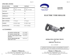
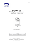
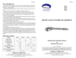
SM-156
SM-156
SPECIFICATIONS
909-1600
909-1700
Model no.
Type
Free Speed (RPM)
Min. Torque Ft-Lb
Max. Torque Ft-Lb
Air Pressure psi
Air Inlet
Hose
Air Flow @Free
Speed
Spindle
Weight
909-1600
909-1700
Lever Throttle
Stall Type
Lever Throttle
Stall Type
160
95
10
10
165
240
90
90
1/2” NPT
1/2” NPT
1/2” I.D.
1/2” I.D.
72 CFM
72 CFM
3/4” square
3/4” square
13.3 Lb (6.0kg)
13.3 Lb (6.0kg)
SERIES 909
RIGH ANGLE TUBE ROLLER
OPERATING INSTRUCTIONS
&
SERVICE MANUAL
Rev: A, 2/26/2007
TO REDUCE THE RISK OF INJURY AND EQUIPMENT DAMAGE
USER MUST READ AND UNDERSTAND OPERATOR’S MANUAL.
12
Thomas C. Wilson, Inc.
Thomas C. Wilson, Inc.
21-11 44th Avenue, Long Island City, New York 11101
Tel: (718)729-3360 Fax: (718)361-2872 http://www.tcwilson.com
E-mail: [email protected]
21-11 44th Avenue, Long Island City, New York 11101
Tel: (718)729-3360 Fax: (718)361-2872 http://www.tcwilson.com
E-mail: [email protected]
SM-156
SAFETY INSTRUCTIONS
SM-156
TROUBLE-SHOOTING
PROBLEM
!
WARNING!
Motor will not run.
CAUSE & REMEDY
1.
READ AND UNDERSTAND ALL INSTRUCTIONS
Failure to follow all instructions listed below, may result in
accident, fire and/or personal injury.
Inefficient air supply
—Check 90 psi and 72 CFM air supply.
2.
Clogged air inlet screen
—Replace.
SAVE THESE INSTRUCTIONS
3.
Broken or severely worn rotor blades
—Replace.
4.
Rust due to improper storage of tool
—Disassemble and clean– Refer to Disassembly
procedure.
5.
Broken throttle valve pin or lever
1.
Insufficient air volume
—Check 72 CFM supply.
Dirty air inlet screen
—Clean.
Worn rotor blades
—Replace.
Air supply hose chocked or too small
—See Operating Procedure recommended hose.
1.
Do not allow corrosive gases or foreign material to enter the unit. Moisture, oilbased contaminants, or other liquids must be filtered out.
2.
Eye protection is always required when running motor.
3.
Hearing protection is recommended when in close proximity to all operating air
motors.
4.
Dust mask, non-skid safety shoes, hard hat, gloves and other personal safety equipment must be used.
Motor will not reach
RPM.
2.
5.
Stay alert, watch what you are doing, and use common sense when operating a
power tool.
6.
Dress properly. Do not wear loose clothing or jewelry.
7.
Keep your work area clean and well lit.
8.
Do not operate power tools in explosive atmospheres, such as in the presence of
flammable liquids, gases, or dust.
9.
Disconnect the tool from the air supply before installing, making any adjustment,
changing accessories, servicing or storing tool.
3.
4.
Motor stalls at high torque 1.
2.
3.
Motor fails to stop
2
1.
2.
Insufficient air pressure
—Check 90 psi supply
Dirty air inlet screen
—Clean.
Rotor blades worn, chipped or broken
—Replace.
Broken throttle valve spring
—Replace.
Valve ball does not seal
—Replace or rework valve seat.
11
DISASSEMBLY
SM-156
SM-156
Before starting to disassemble or reassemble this tool ( any part or completely )
be sure to read MAINTENANCE Section.
The basic sections and instructions for removing them from are as follows:
RIGHT-ANGLE SECTION
Using wrenches on flats of Lock Ring (Key #12 ), loosen Ring completely and
pull Right-Angle Section from gearing.
GEARING SECTION
Hold motor housing on flats in a vise, and remove gearing section using a
wrench on flats of Lock Ring (Key #12). Separate Drive Gearing from Auxiliary Gearing.
MOTOR AND THROTTLE SECTION
The remaining section becomes the Motor and Throttle Section.
Unscrew Stack-Up Nut (Key #30) and lift out Rotor Assembly. Remove Retaining Ring (Key #19) to disassembly Rotor and Rotor Blades.
OPERATION
Always operate, inspect and maintain this tool in accordance with American National
Standards Institute Safety Code for Portable Air Tools (ANSI B186.1) and any other
applicable safety codes and regulations.
FOR TOP PERFORMANCE AND MAXIMUM DURABILITY OF PARTS, OPERATE THIS TOOL AT 90 psig (6.2bar/620kPa) AIR PRESSURE WITH ½” (13mm)
DIAMETER HOSE.
WARNING: Always turn off the air supply and disconnect the air supply hose before
installing, removing or adjusting any accessory on this tool, or before performing any
maintenance on this tool. Failure to do could result in injury.
Air powered tools can vibrate in use. Repetitive motions, uncomfortable positions,
vibrations can cause injury to hands, fingers, wrists of some persons. Stop using any
tool if discomfort, tingling felling or pain occurs. Seek medical advice before resuming use.
HOSE AND HOSE CONNECTIONS
Use ½” (13mm) hose or hose fitting with a Male Hose Nipple (1/2” hose to ½” male
pipe) for attaching it to the tube Roller. A smaller hose or hose fitting will reduce the
power and efficiency of the Tube Roller.
LUBRICATION
After each two or three hours of operation, unless an Air Line Lubricator is used, disconnect the air hose and pour into the inlet about 3cc of SAE No. 10 or ‘Wilsolub’
Pneumatic motor oil Cat. No. 9047.
The use of an Air Line Lubricator is recommended with any air-operated tool. Install
an Wilson automatic lubricator Cat. No. 8597 as close to the tool as possible.
Gearing and Right-Angle Assembly should be grease lubricated approximately every
160 hours of operation. Inject bearing type grease, 1 to 2 strokes through grease fitting
in housing. Grease Gun Nozzle Cat No. 53553-0001 is supplied with the tool.
OPERATION INSTRUCTIONS
Never operate this tool unless its dead handle/reaction bar is held firmly against a solid
mass.
Do not use a heavy oil or gum-forming oil. The use of either will cause sluggish, inefficient performance.
Use only clean oil. Dirty oil will cause cutting and scoring of internal parts.
Weekly, or before storing the Tool for a long time, put a liberal amount of oil into the
Air Inlet. Also keep operating air moisture to a minimum. Compressor after coolers,
air line traps, water separators, and rust inhibiting oil can help.
Clean or replace rusted parts during service check.
10
3
SM-156
SM-156
MAINTENANCE
Disassembly should be done on a clean work bench with a clean cloth spread to
prevent the loss of small parts. After disassembly is completed; all parts should be
thoroughly washed in a clean solvent, blown dry with air and inspected for wear
levels, abuse and contamination.
Double sealed or shielded bearings should never be placed in solvent unless a good
method of re-lubricating the bearing is available. Open bearings may be washed
but should not be allowed to spin while being blown dry. When replacement parts
are necessary, consult drawing containing the parts for identification.
Before reassembling, lubricate parts where required. Use bearing grade grease in
bearings. When assembling ‘O’ ring, care must be exercised to prevent damage to
the rubber sealing surfaces. A small amount of grease will usually hold steel balls
and small parts in place while assembling.
ITEM
1
2
3
4
5
6
7
8
9
10
11
12
13
14
15
16
17
When ordering parts, be sure to list PART NUMBER, PART NAME, MODEL
NUMBER AND SERIAL NUMBER OF TOOL. USE ONLY GENIUE REPLACEMENT PARTS.
NOTES:
1. LOCTITE ITEM 7 IN PLACE.
2. PRESS FIT ITEM 25 INTO ITEM 24.
3. PRESS FIT ITEM 1 INTO ITEM 18.
4. PRESS FIT ITEM 6 AND 33 INTO ITEM 31.
5. PRESS FIT ITEM 32 INTO ITEM 16.
6. APPLY LIGHT GEAR GREASE TO ITEM 29.
7. APPLY LIGHT OIL TO ITEM 14.
8. INSERT POINTED END OF ITEM 26 INTO HOLE IN
ITEM 23.
It is important that the correct tools and fixtures are used when servicing this tool.
ITEM
QTY PART NO
18
1 909-3294
19
2 909-3521
20
1 909-3589
21
1 909-3590
22
1 909-5112
23
1 909-5113
24
1 909-5135
25
1 909-5136
26
1 909-5355
27
1 909-5356
28
1 909-6481
29
1 909-6537
909-1600
1 909-6536
30
1 909-6703
31
1 909-6710
32
1 909-6989
33
1 909-S106
When removing or installing bearing, apply pressure to the bearing race that will be
the press fit to mating part; if this is not practiced, Brinelling of the bearing race
may occur making replacement necessary.
DESCRIPTION
ROLL PIN
‘O’ RING
AIR SCREEN
‘O’ RING
‘O’ RING
BEARING
THREADED PIN
‘O’ RING
‘O’ RING
ROLL PIN
SLEEVE
INLET FITTING
CAP
ROTOR BLADE
UPPER END PLATE
REVERSING VALVE
BUTTON
Excessive pressure exerted by a holding device may cause distortion of a part. Apply pressure evenly when disassembling ( or assembling ) parts which have a press
fit.
PART NO
25171-0000
50915-0000
51179-0000
8653-0000
8659-0000
909-0511
909-0716
909-0828
909-0973
909-103P
909-1091
909-1092
909-1273
909-2584X
909-3291
909-3292
909-3293
Air tools are made of precision parts and should be handled with reasonable care
when servicing.
QTY
2
1
1
1
1
2
1
1
1
3
1
1
1
5
1
1
1
Always turn off the air supply and disconnect the air supply hose before installing, removing or adjusting any accessory on this tool, or before performing any maintenance on this tool. Failure to do could result in injury.
DESCRIPTION
CYLINDER
RETAINING RING
ACTUATING RING
SPRING
LEVER
VALVE STEM
MOTOR HOUSING
BUSHING
THROTTLE VALVE
VALVE SEAT
SPRING
ROTOR
ROTOR
STACK-UP NUT
LOWER END PLATE
PLUG
PIN
WARNING
4
9
PART NO.
909-1600
909-3939
909-4940
909-5940
PART NO.
909-1700
909-3939
909-4939
909-5939
8
1
1
1
QTY
RIGHT ANGLE HEAD ASSY
GEAR TRAIN ASSEMBLY
THROTTLE & AIR MOTOR ASSEMBLY
DESCRIPTION
PARTS LIST, 909-5939 & 909-5940
1
2
3
KEY
SM-156
SM-156
PARTS LIST
5
SM-156
PARTS LIST,
SM-156
PARTS LIST, 909-3939
NOTES:
1. PRESS FIT ITEM 3 INTO ITEM 13.
2. PRESS FIT ITEM 4 INTO ITEM 14.
3. APPLY LIGHT GEAR GREASE TO ITEM 20 AND 21.
4. APPLY LIGHT BEARING GREASE TO ALL BEARINGS.
5. RETAIN ITEM 18 WITH 19.
NOTES:
1. PRESS FIT ITEM 20 INTO ITEM 16.
2. PRESS FIT ITEM 23 INTO ITEM 10.
3. APPLY LIGHT GEAR GREASE TO ITEM 10, 17 AND 22.
4. APPLY LIGHT BEARING GREASE TO ALL BEARINGS.
6
ITEM
QTY PART NO
DESCRIPTION
1
1 21946-0000 WASHER
2
1 28041-0000 NUT
3
1 909-0218 RETAINING RING
4
1 909-3350 RETAINING RING
5
1 909-0512 NEEDLE ROLLER BEARING
6
1 909-0887 KEY
7
2 909-0923 ‘O’ RING
8
2 909-1281 LOCK SLEEVE
9
1 909-151P SOCKET HEAD SCREW
10
1 909-2950 GEAR CASE
11
1 909-2953 REACTION BAR COLLAR
12
1 909-2957 LOCK NUT
13
3 909-2973 MUFFLER
14
3 909-2985 THRUST WASHER
15
1 909-3217 LOWER GEAR CASE
16
1 909-3218 UPPER GEAR CASE
17
3 909-3227 LOWER IDLER GEAR
909-1600
1 909-3228 LOWER IDLER GEAR
18
3 909-3233 IDLER PIN
19
3 909-3236 IDLER PIN
20
1 909-3239 SHORT SPINDLE GEAR
909-1600
1 909-3238 SHORT SPINDLE GEAR
21
1 909-0201 RETAINING RING
22
3 909-3533 UPPER IDLER GEAR
909-1600
3 909-3534 UPPER IDLER GEAR
23
1 909-3943 BEARING
ITEM
1
2
3
4
5
6
7
8
9
10
11
12
13
14
15
16
17
18
19
20
21
22
QTY
1
1
1
1
1
1
1
1
1
1
1
1
1
1
2
1
1
2
1
1
1
1
PART NO
52287-0000
71685-0009
909-0507
909-0510
909-2553
909-2983
909-3002
909-3154
909-3219
909-3230
909-3235
909-3242
909-3245
909-3253
909-3945
909-3946
909-4883
909-5539
909-6483
909-6730
909-6744
909-9141
DESCRIPTION
GREASE FITTING
RETAINING RING
BEARING
BEARING
THRUST WASHER
THRUST WASHER
RETAINING RING
THRUST BEARING
SINGLE END SPINDLE
THRUST WASHER
THRUST BEARING RACE
LOCK NUT
RETAINING NUT
ANGLE DRIVE HOUSING
BEARING ASSEMBLY
BEARING SPACER
GREASE SEAL
SPLIT RING
ELASTIC RING
SPLINED ADAPTER
GEAR SET
THRUST BEARING
7
SM-156
PARTS LIST,
SM-156
PARTS LIST, 909-3939
NOTES:
1. PRESS FIT ITEM 3 INTO ITEM 13.
2. PRESS FIT ITEM 4 INTO ITEM 14.
3. APPLY LIGHT GEAR GREASE TO ITEM 20 AND 21.
4. APPLY LIGHT BEARING GREASE TO ALL BEARINGS.
5. RETAIN ITEM 18 WITH 19.
NOTES:
1. PRESS FIT ITEM 20 INTO ITEM 16.
2. PRESS FIT ITEM 23 INTO ITEM 10.
3. APPLY LIGHT GEAR GREASE TO ITEM 10, 17 AND 22.
4. APPLY LIGHT BEARING GREASE TO ALL BEARINGS.
6
ITEM
QTY PART NO
DESCRIPTION
1
1 21946-0000 WASHER
2
1 28041-0000 NUT
3
1 909-0218 RETAINING RING
4
1 909-3350 RETAINING RING
5
1 909-0512 NEEDLE ROLLER BEARING
6
1 909-0887 KEY
7
2 909-0923 ‘O’ RING
8
2 909-1281 LOCK SLEEVE
9
1 909-151P SOCKET HEAD SCREW
10
1 909-2950 GEAR CASE
11
1 909-2953 REACTION BAR COLLAR
12
1 909-2957 LOCK NUT
13
3 909-2973 MUFFLER
14
3 909-2985 THRUST WASHER
15
1 909-3217 LOWER GEAR CASE
16
1 909-3218 UPPER GEAR CASE
17
3 909-3227 LOWER IDLER GEAR
909-1600
1 909-3228 LOWER IDLER GEAR
18
3 909-3233 IDLER PIN
19
3 909-3236 IDLER PIN
20
1 909-3239 SHORT SPINDLE GEAR
909-1600
1 909-3238 SHORT SPINDLE GEAR
21
1 909-0201 RETAINING RING
22
3 909-3533 UPPER IDLER GEAR
909-1600
3 909-3534 UPPER IDLER GEAR
23
1 909-3943 BEARING
ITEM
1
2
3
4
5
6
7
8
9
10
11
12
13
14
15
16
17
18
19
20
21
22
QTY
1
1
1
1
1
1
1
1
1
1
1
1
1
1
2
1
1
2
1
1
1
1
PART NO
52287-0000
71685-0009
909-0507
909-0510
909-2553
909-2983
909-3002
909-3154
909-3219
909-3230
909-3235
909-3242
909-3245
909-3253
909-3945
909-3946
909-4883
909-5539
909-6483
909-6730
909-6744
909-9141
DESCRIPTION
GREASE FITTING
RETAINING RING
BEARING
BEARING
THRUST WASHER
THRUST WASHER
RETAINING RING
THRUST BEARING
SINGLE END SPINDLE
THRUST WASHER
THRUST BEARING RACE
LOCK NUT
RETAINING NUT
ANGLE DRIVE HOUSING
BEARING ASSEMBLY
BEARING SPACER
GREASE SEAL
SPLIT RING
ELASTIC RING
SPLINED ADAPTER
GEAR SET
THRUST BEARING
7
PART NO.
909-1600
909-3939
909-4940
909-5940
PART NO.
909-1700
909-3939
909-4939
909-5939
8
1
1
1
QTY
RIGHT ANGLE HEAD ASSY
GEAR TRAIN ASSEMBLY
THROTTLE & AIR MOTOR ASSEMBLY
DESCRIPTION
PARTS LIST, 909-5939 & 909-5940
1
2
3
KEY
SM-156
SM-156
PARTS LIST
5
SM-156
SM-156
MAINTENANCE
Disassembly should be done on a clean work bench with a clean cloth spread to
prevent the loss of small parts. After disassembly is completed; all parts should be
thoroughly washed in a clean solvent, blown dry with air and inspected for wear
levels, abuse and contamination.
Double sealed or shielded bearings should never be placed in solvent unless a good
method of re-lubricating the bearing is available. Open bearings may be washed
but should not be allowed to spin while being blown dry. When replacement parts
are necessary, consult drawing containing the parts for identification.
Before reassembling, lubricate parts where required. Use bearing grade grease in
bearings. When assembling ‘O’ ring, care must be exercised to prevent damage to
the rubber sealing surfaces. A small amount of grease will usually hold steel balls
and small parts in place while assembling.
ITEM
1
2
3
4
5
6
7
8
9
10
11
12
13
14
15
16
17
When ordering parts, be sure to list PART NUMBER, PART NAME, MODEL
NUMBER AND SERIAL NUMBER OF TOOL. USE ONLY GENIUE REPLACEMENT PARTS.
NOTES:
1. LOCTITE ITEM 7 IN PLACE.
2. PRESS FIT ITEM 25 INTO ITEM 24.
3. PRESS FIT ITEM 1 INTO ITEM 18.
4. PRESS FIT ITEM 6 AND 33 INTO ITEM 31.
5. PRESS FIT ITEM 32 INTO ITEM 16.
6. APPLY LIGHT GEAR GREASE TO ITEM 29.
7. APPLY LIGHT OIL TO ITEM 14.
8. INSERT POINTED END OF ITEM 26 INTO HOLE IN
ITEM 23.
It is important that the correct tools and fixtures are used when servicing this tool.
ITEM
QTY PART NO
18
1 909-3294
19
2 909-3521
20
1 909-3589
21
1 909-3590
22
1 909-5112
23
1 909-5113
24
1 909-5135
25
1 909-5136
26
1 909-5355
27
1 909-5356
28
1 909-6481
29
1 909-6537
909-1600
1 909-6536
30
1 909-6703
31
1 909-6710
32
1 909-6989
33
1 909-S106
When removing or installing bearing, apply pressure to the bearing race that will be
the press fit to mating part; if this is not practiced, Brinelling of the bearing race
may occur making replacement necessary.
DESCRIPTION
ROLL PIN
‘O’ RING
AIR SCREEN
‘O’ RING
‘O’ RING
BEARING
THREADED PIN
‘O’ RING
‘O’ RING
ROLL PIN
SLEEVE
INLET FITTING
CAP
ROTOR BLADE
UPPER END PLATE
REVERSING VALVE
BUTTON
Excessive pressure exerted by a holding device may cause distortion of a part. Apply pressure evenly when disassembling ( or assembling ) parts which have a press
fit.
PART NO
25171-0000
50915-0000
51179-0000
8653-0000
8659-0000
909-0511
909-0716
909-0828
909-0973
909-103P
909-1091
909-1092
909-1273
909-2584X
909-3291
909-3292
909-3293
Air tools are made of precision parts and should be handled with reasonable care
when servicing.
QTY
2
1
1
1
1
2
1
1
1
3
1
1
1
5
1
1
1
Always turn off the air supply and disconnect the air supply hose before installing, removing or adjusting any accessory on this tool, or before performing any maintenance on this tool. Failure to do could result in injury.
DESCRIPTION
CYLINDER
RETAINING RING
ACTUATING RING
SPRING
LEVER
VALVE STEM
MOTOR HOUSING
BUSHING
THROTTLE VALVE
VALVE SEAT
SPRING
ROTOR
ROTOR
STACK-UP NUT
LOWER END PLATE
PLUG
PIN
WARNING
4
9
DISASSEMBLY
SM-156
SM-156
Before starting to disassemble or reassemble this tool ( any part or completely )
be sure to read MAINTENANCE Section.
The basic sections and instructions for removing them from are as follows:
RIGHT-ANGLE SECTION
Using wrenches on flats of Lock Ring (Key #12 ), loosen Ring completely and
pull Right-Angle Section from gearing.
GEARING SECTION
Hold motor housing on flats in a vise, and remove gearing section using a
wrench on flats of Lock Ring (Key #12). Separate Drive Gearing from Auxiliary Gearing.
MOTOR AND THROTTLE SECTION
The remaining section becomes the Motor and Throttle Section.
Unscrew Stack-Up Nut (Key #30) and lift out Rotor Assembly. Remove Retaining Ring (Key #19) to disassembly Rotor and Rotor Blades.
OPERATION
Always operate, inspect and maintain this tool in accordance with American National
Standards Institute Safety Code for Portable Air Tools (ANSI B186.1) and any other
applicable safety codes and regulations.
FOR TOP PERFORMANCE AND MAXIMUM DURABILITY OF PARTS, OPERATE THIS TOOL AT 90 psig (6.2bar/620kPa) AIR PRESSURE WITH ½” (13mm)
DIAMETER HOSE.
WARNING: Always turn off the air supply and disconnect the air supply hose before
installing, removing or adjusting any accessory on this tool, or before performing any
maintenance on this tool. Failure to do could result in injury.
Air powered tools can vibrate in use. Repetitive motions, uncomfortable positions,
vibrations can cause injury to hands, fingers, wrists of some persons. Stop using any
tool if discomfort, tingling felling or pain occurs. Seek medical advice before resuming use.
HOSE AND HOSE CONNECTIONS
Use ½” (13mm) hose or hose fitting with a Male Hose Nipple (1/2” hose to ½” male
pipe) for attaching it to the tube Roller. A smaller hose or hose fitting will reduce the
power and efficiency of the Tube Roller.
LUBRICATION
After each two or three hours of operation, unless an Air Line Lubricator is used, disconnect the air hose and pour into the inlet about 3cc of SAE No. 10 or ‘Wilsolub’
Pneumatic motor oil Cat. No. 9047.
The use of an Air Line Lubricator is recommended with any air-operated tool. Install
an Wilson automatic lubricator Cat. No. 8597 as close to the tool as possible.
Gearing and Right-Angle Assembly should be grease lubricated approximately every
160 hours of operation. Inject bearing type grease, 1 to 2 strokes through grease fitting
in housing. Grease Gun Nozzle Cat No. 53553-0001 is supplied with the tool.
OPERATION INSTRUCTIONS
Never operate this tool unless its dead handle/reaction bar is held firmly against a solid
mass.
Do not use a heavy oil or gum-forming oil. The use of either will cause sluggish, inefficient performance.
Use only clean oil. Dirty oil will cause cutting and scoring of internal parts.
Weekly, or before storing the Tool for a long time, put a liberal amount of oil into the
Air Inlet. Also keep operating air moisture to a minimum. Compressor after coolers,
air line traps, water separators, and rust inhibiting oil can help.
Clean or replace rusted parts during service check.
10
3
SM-156
SAFETY INSTRUCTIONS
SM-156
TROUBLE-SHOOTING
PROBLEM
!
WARNING!
Motor will not run.
CAUSE & REMEDY
1.
READ AND UNDERSTAND ALL INSTRUCTIONS
Failure to follow all instructions listed below, may result in
accident, fire and/or personal injury.
Inefficient air supply
—Check 90 psi and 72 CFM air supply.
2.
Clogged air inlet screen
—Replace.
SAVE THESE INSTRUCTIONS
3.
Broken or severely worn rotor blades
—Replace.
4.
Rust due to improper storage of tool
—Disassemble and clean– Refer to Disassembly
procedure.
5.
Broken throttle valve pin or lever
1.
Insufficient air volume
—Check 72 CFM supply.
Dirty air inlet screen
—Clean.
Worn rotor blades
—Replace.
Air supply hose chocked or too small
—See Operating Procedure recommended hose.
1.
Do not allow corrosive gases or foreign material to enter the unit. Moisture, oilbased contaminants, or other liquids must be filtered out.
2.
Eye protection is always required when running motor.
3.
Hearing protection is recommended when in close proximity to all operating air
motors.
4.
Dust mask, non-skid safety shoes, hard hat, gloves and other personal safety equipment must be used.
Motor will not reach
RPM.
2.
5.
Stay alert, watch what you are doing, and use common sense when operating a
power tool.
6.
Dress properly. Do not wear loose clothing or jewelry.
7.
Keep your work area clean and well lit.
8.
Do not operate power tools in explosive atmospheres, such as in the presence of
flammable liquids, gases, or dust.
9.
Disconnect the tool from the air supply before installing, making any adjustment,
changing accessories, servicing or storing tool.
3.
4.
Motor stalls at high torque 1.
2.
3.
Motor fails to stop
2
1.
2.
Insufficient air pressure
—Check 90 psi supply
Dirty air inlet screen
—Clean.
Rotor blades worn, chipped or broken
—Replace.
Broken throttle valve spring
—Replace.
Valve ball does not seal
—Replace or rework valve seat.
11
SM-156
SM-156
SPECIFICATIONS
909-1600
909-1700
Model no.
Type
Free Speed (RPM)
Min. Torque Ft-Lb
Max. Torque Ft-Lb
Air Pressure psi
Air Inlet
Hose
Air Flow @Free
Speed
Spindle
Weight
909-1600
909-1700
Lever Throttle
Stall Type
Lever Throttle
Stall Type
160
95
10
10
165
240
90
90
1/2” NPT
1/2” NPT
1/2” I.D.
1/2” I.D.
72 CFM
72 CFM
3/4” square
3/4” square
13.3 Lb (6.0kg)
13.3 Lb (6.0kg)
SERIES 909
RIGH ANGLE TUBE ROLLER
OPERATING INSTRUCTIONS
&
SERVICE MANUAL
Rev: A, 2/26/2007
TO REDUCE THE RISK OF INJURY AND EQUIPMENT DAMAGE
USER MUST READ AND UNDERSTAND OPERATOR’S MANUAL.
12
Thomas C. Wilson, Inc.
Thomas C. Wilson, Inc.
21-11 44th Avenue, Long Island City, New York 11101
Tel: (718)729-3360 Fax: (718)361-2872 http://www.tcwilson.com
E-mail: [email protected]
21-11 44th Avenue, Long Island City, New York 11101
Tel: (718)729-3360 Fax: (718)361-2872 http://www.tcwilson.com
E-mail: [email protected]