1
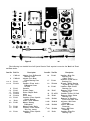
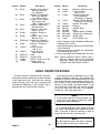
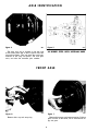
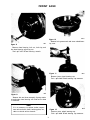
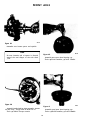
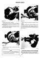
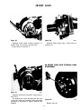
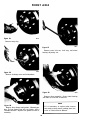
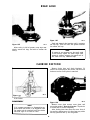
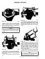
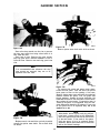
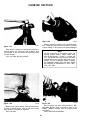
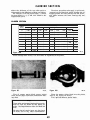
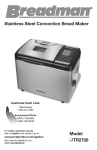
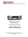
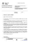
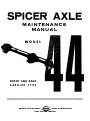
MAINTENANCE MANUAL MODEL FRONT AND REAR CA RRIER TYPE SPICER AXLE DIVISION -<$::> DANA CORPORATION FORT WAYNE, INDIANA INDEX Page 3 LUBRICATION IDENTIFICATION OF SERVICE TOOLS -------- - - ---------- ------- --- -- -- - - - AXLE IDENTIFICATION------------------------------------------------- 4-5 5 FRONT AXLES - WHEEL ENDS 40° Steer Ball Socket ------ ---- --- ------ ------ -- ------------ - - - - Closed Knuckle Design ----------- -------- ---- - - 6-19 - ------- ------ 20-26 -- - - REAR AXLES- WHEEL ENDS Unit Wheel Bearing (Lubricated with Hypoid Gear Lube} _______________ Unit Wheel Bearing (Lubricated with Grease} -- - ------------- - 27-29 ---- 29-32 -- Unit Wheel Bearing Removal and Installation -------------------- ---- 32-34 - CARRIER SECTION ---- --- --- ----- -- --- 35-49 ___________________________ - - - - - IMPORTANT SAFETY NOTICE Should an axle assembly require component parts replacement, it is recommended that "Original Equipment" replacement parts be used. They may be obtained through your local service dealer or other original equip ment manufacturer parts supplier. CAUTION: THE USE OF NON-ORIGINAL EQUIPMENT REPLACE MENT PARTS IS NOT RECOMMENDED AS THEIR USE MAY CAUSE UNIT FAILURE AND/OR AFFECT VEHICLE SAFETY. Proper service and repair is important to the safe, reliable operation of all motor vehicles or driving axles whether they be front or rear. The service procedures recommended and described in this service manual are effective methods for performing service operations. Some of these service operations require the use of tools specially designed for the purpose. The special tool should be used when and as recommended. It is impossible to know, evaluate and advise the service trade of all conceivable ways in which service might be done or of the possible hazardous consequences of each way. Accordingly, anyone who uses a service procedure or tool which is not recommended must first satisfy himself thoroughly that neither his safety or vehicle safety will be jeopardized by the service methods he selects. NOTE Throughout this manual, reference is made to certain tool numbers whenever special tools are required. These numbers are numbers of the Miller Special Tools, 32615 Park Lane, Garden City, Michigan 48135. They are used herein for customer convenience only. Dana Corporation makes no warranty or representation with respect to these tools. © 1972 DANA CORPORATION 2 Litho in U.S.A. LUBRICATION It is not our intent to recommend any particular brand or make of lubricant for Spicer axles. However, a S.A.E. 90 weight multipurpose gear lubricant meeting Mil. Spec. L-2105-B, or 80 W 90 multipurpose gear lubricant meeting Mil. Spec. L-2105-C, and suitable for A.P. I. Service Classificiation GL-5 is suggested as a minimum requirement. IMPORTANT As special equipment limited slip differentials are provided in many vehicles, the freedom from "chatter" is a function of the lubricant used and cannot be covered in the above specifications. In some applications, a special limited slip differential lubricant may be required. If required, these special lubricants are normally available through the original equipment manufacturer. WHEEL BEARING LUBRICATION Wheel bearings are lubricated by either grease packing the wheel bearing itself, or it can be lubri cated from the hypoid gear lube in the housing. For grease packing it is recommended that' a number 2 consistency, lithium base 12 hydroxy stearate grease containing an E.P. additive be used. Such a lubricant would pass a load-carrying test at 40 pounds minimum with base oil pour point at -10" F. maximum. Wheel bearings which depend on lubrication from the hypoid gear lube in the axle housing, it is recommended that a S.A.E. 90 multipurpose gear lube meeting Mil. Spec. L-2105-B be used. CLOSED WHEEL END STEERING KNUCKLE LUBRICATION The closed steering knuckle requires lubrication from a source other than the gear carrier assem bly. Inboard tube seals contain the hypoid gear lube in the housing to provide an adequate lubricant level for the gears, bearings, etc. This then requires an additional lubricant level to be maintained out board, in each steering knuckle, which can be observed by removing fill plugs on each knuckle. Adequate level would be to the bottom of the fill plug hole, when vehicle is observed to be in a normal horizontal position. Recommended lubricant is a S.A.E. 140 grade, multipurpose gear lubricant meeting the Mil-L2105-B specification. COLD WEATHER OPERATION If the vehicle is operated below 0 °F ( -18 °C), it is advisable to use S.A.E. 80 multipurpose gear lubricant meeting Mil. Spec. L-2105-B and suitable for A. P.I. Service Classification GL-5. SUBMERSION OR DEEP WATER FORDING If the vehicle is exposed to water deep enough to cover the hubs of either the front or rear axles, it is recommended that the wheel ends be dissassembled and inspected for water damage, and/or con tamination daily. Clean, examine and replace damaged parts if necessary, prior to relubricating and assembling the wheel end components. Pay particular attention to the bearings and the closed steering knuckle on the front driving axle. In the event the gear carrier housing should become submerged in water, particularly if over the breathers, it is recommended that the hypoid gear lubricant be drained daily and internal parts be in spected for water damage and/or contamination. Clean, examine and replace damaged parts if necessary, prior to assembling the cover housing and refilling with the specified hypoid lubricant. NOTE It is recommended that whenever bearings are removed they are to be replaced with new ones, regardless of mileage. 3 t,J 17It- • • ' � , 21 � - ,.)f - 12 t 12 0 J - ti -- li .; 100'1-2 Figure 2 The following is a detailed list of all Special Service Tools required to service the Model 44 Front and Rear Axles. 1 C-293-18 Adapter Set-Differential Bearing Cones 2 C-293-39 Adapter Set-Rear Pinion Bearing Cone **** 3 **** 4 D-112 Screw D-112-1 Installer-Front AxleDifferential Inner Oil Seal 5 D-113 Spreader 6 D-115 Scooter Gauge • * 7 D-115-1 Pinion Height Block 8 D-115-3 Arbor * 9 D-115-4 Arbor Discs 10 D-112 Installer-Front Spindle Needle Bearing 11 * 12 D-131 Puller-Slide Hammer D-135 Master Bearing Differential * 13 D-139 Master Pinion Block 14 D-140 Installer-Front Brake Hub Cup (outer) 15 D-141 Installer-Front Spindle Bushing • Item No. Tool No. Description Item No. Tool No. 16 D-142 Installer-King Pin Bearing Cup (Heavy Duty) 17 D-144 Installer-Front Pinion Bearing Cup 18 W-144A Wrench-Wheel Bearing Adjusting (Nut Type) 19 D-145 Installer-Rear Pinion Bearing Cup 20 D-147 Remover-Front Pinion Bearing Cup 21 W-147-D Installer-Pinion Oil Seal 22 D-148 Remover-Rear Pinion Bearing Cup Remover & InstallerFront Axle Ball Joint Adjuster-Ball Joint Removing Sleeve-Ball Joint Removing Sleeve--Ball Joint Installing Installer-King Pin Bearing Cup ***23 D-150-1 ***24 D-150-2 ***25 D-150-3 ***26 D-150-4 27 4 Description D-151 Item No. Tool No. 28 D-153 Description Item No. Tool No. Description Installer-Front Brake Hub Inner Bearing Cup (Regular) 43 C-4049 Remover-Bearing Cups 44 C-4053 Torque Wrench (300 ft. lb.) 29 D-154 Installer-Front Brake Hub Inner Bearing Cup (Heavy Duty) 45 C-4169 30 D-155 Installer-Front Brake Hub Grease Seal (Reg. & Heavy Duty) Wrench-Upper Ball Joint Removing, Installing & Torquing 46 C-4170 Wrench-Wheel Bearing Adjusting (Lug Type) 31 D-156 Installer-Differential Side Bearings 47 C-4171 Handle-Universal **48 SP-3020 Washers 32 D-157 Installer-Axle Shaft Outer Oil Seal **49 SP-5017 Adapter Ring **50 SP-5026 Bolts 33 W-162 Installer-Flange or Yoke Adapter Plate-Installer 34 W-262 Installer-Rear Pinion Bearing Cone W-343-44D Remover & InstallerAxle Shaft Bearings 36 C-452 Remover-Flange or Yoke 37 C-524-A Torque Wrench (100 ft. lb. ) 38 C-685-A Torque Wrench (300 inch lb.) 39 DD-914-P Press 40 DD-914-9 Adapter Ring 41 C-3281 Holder-Flange or Yoke 42 C-293-3 Adapter PlugDifferential Hub **35 **51 SP-5439 **52 SP-5442-D Adapter Set-Removing **53 SP-5443-A Flange Piate D-128 Dial Indicator Set 54 *Pinion Setting Gauge and Master Differential Bearing Kit D-115-44 **Axle Shaft Bearing Removing and Installing Kit W-343-44D ***40 Degree Steer Front Ball Joint Removing and Installing Kit D-150 ****Inner Axle Shaft Seal Installing Kit D-112-44 Note: Torque wrenches C-524A, C-685-A, and C- 4053 are optional and can be purchased separately. These Torque wrenches are not included in the DW-44 Axle Tool Kit. AXLE IDENT IF ICAT ION All Spicer axles are identified with a manufac In the figure the axle is identified with %" high numbers stamped in the tube. For example, the numbers 10-10-2 A5 is the manufacturing or build date of the axle and is interpreted as follows. The first number is the month, the second number is the day of the month, the third number is the year, the letter is the shift and the last number is the line that built the axle. For example: October 10, 1972, first shift, line 5. turing date and the complete part number stamped in the right hand tube. Also each axle contains a gear ratio tag ; and if the axle is equipped with a limited slip differential, it will contain a tag re questing the use of limited slip lubricant. NOTE In the event there are two build dates, the latter will be the date in which the brake components were assembled. It is recommended that when referring to the axle, obtain the complete part number and build date. To do this, it may be necessary to wipe or scrape off the dirt, etc. , from the tube. NOTE On front driving axles, the above numbers Figure 3 can be either on the long or short tube. 1009-3 5 AXLE IDENT IF ICAT ION Figure 4 Figure 5 1009-4 1009-5 40 DEGREE STEER WITH INTERNAL HUBS The gear ratio tag is located on the left side of the cover plate and is held in place with two cover plate screws. This tag gives the tooth com bination of the ring and pinion, the total gear ratio, and also the customer part number. FRONT AXLE Figure 6 Figure 7 1 009-6 1009-7 Remove drive gear and pressure spring. If drive gear is stuck to the shaft, use a screw driver to pry out gear. Remove hub cap and snap ring. 6 FRONT AXLE Figure 10 Figure 8 100'1-10 Remove hub grease seal and inner wheel bear ing cone. 100'1-8 Remove wheel bearing lock nut, lock ring and the wheel bearing adjusting nut. Tool-#C-4170 Wheel bearing wrench. Figure 11 100'1-11 Remove inner wheel bearing cup. Tool-#C-4049 Wheel bearing cup remover. Figure 9 1 00'1-9 Remove hub and drum assembly. Spring retain er and outer wheel bearing will slide out as drum is removed. NOTE If it is necessary to replace brake compon Figure 1 2 ents such as drum, shoes, backing plate, etc., 1009-12 Remove outer wheel bearing cup. refer to vehicle service manual. Tool-#C-4049 Wheel bearing cup remover. 7 FRONT AXLE Figure 1 3 Figure 1 5 1009-13 1009-15 Place spindle in vise. Do not locate on bearing Remove backing plate screws and remove back ing plate. diameters. Remove grease seal. Discard seal. Tool-#D-131 Slide hammer. NOTE The brake backing plate assembly can be re tained with screws or nuts_ NOTE If the nuts are Be sure that vise jaws are equipped with of the torque prevailing design, they are to brass protectors or similar type to protect be replaced with new ones. the machined surfaces of any parts that are to be placed in the vise. Figure 1 4 Figure 1 6 1 009-14 1009-16 Remove needle bearing. Bronze bushing may stick to the bearing as the spindle was removed, but can be removed when removing the needle bearing as shown. Remove spindle. If necessary tap lightly with a rawhide hammer to free it from the knuckle. Check brone spacer located between shaft joint assembly and bearing. If wear is evident, replace with a new one. Tool-#D-131 Slide hammer. 8 FRON T AXLE Figure 17 Figure 19 1009-17 Using a rawhide hammer, hit sharply on the top stud to free the knuckle from the tube yoke. After knuckle is free from the yoke, remove both the top and bottom nuts. Discard bottom nut. The nut on the bottom socket is of the torque prevailing design and is not to be reused. Remove cotter key from tie rod nut. Remove nut. Tap on tie rod stud to free it from the steer ing arm. Figure 18 Remove cotter key from top socket. both the top and bottom nuts. 1009-19 Figure 20 1009-18 1009-20 Remove threaded sleeve from yokes with Tool #C-4169 socket wrench. Loosen 9 FRON T AXLE D-150-3 Sl£EVE Figure 2 1 D-150-2 ADAPTER REMOVER Figure 23 1009-21 Place knuckle in vise as shown. If bottom ball socket is equipped with a snap ring, remove as shown. 1009-23 Assemble ball socket tools as shown. Turn forc ing screw and push out top socket. Discard Ball Socket Tools-#D-150-1 Ball Joint Remover & Install er, #D-150-2 Adapter Remover, and #D-150-3 Sleeve. ASSEMBLY 1).}50-3 SLEEVE D-150-4 INSTAllER Sl£EVE Figure 22 0.150-3 SLEEVE 1009-22 NOTE: BOTTOM BALL SOCKET MUST BE REMOVED BEFORE THE TOP BALL SOCKET CAN BE REMOVED. Figure 24 Assemble ball socket tools as shown. Turn forc ing screw and push out bottom socket. 1009-24 (Lower ball socket does not have a cotter key hole in the stud end.) Assemble bottom socket into the knuckle. Make sure socket is straight. Assemble tools as shown. Turn forcing screw and push socket into knuckle as far as it will go. Tools-#D-150-1 Ball Joint Remover & Install er, #D-150-3 Sleeve, & #D-150-4 Sleeve Installer. DISCARD BALL SOCKET Tools-#D-150-1 Ball Joint Remover & Install er, #D-150-2 Adapter Remover , and #D-150-3 Sleeve. 10 FRON T AXLE Figure 25 Figure 27 1009-25 Assemble knuckle and socket assembly to yoke as shown. If required, assemble snap ring on bottom socket. D-150-4 SLEEVE INSTALLER Figure 26 1009-27 D-150-3 SLEEVE Figure 28 1009-26 1009-28 Assemble new torque prevailing nut on bottom socket finger tight. Assemble top nut on top socket. Do not assem Upper ball socket has a cotter key hole in the stud end. Assemble socket into knuckle. Make sure socket is straight. Assemble tools as shown. Turn forcing screw and push socket into knuckle as far as it will go. Tools-#D-150-1 Ball Joint Installer & Remov er, #D-150-3 Sleeve, & #D-150-4 Sleeve Installer. Remove tools. Make sure this area is free from dirt, etc. ble at this time. Torque top nut until it is tight. This will pull the studs of the bottom socket into the tapered hole of the yoke. Torque bottom nut to 80 lbs. ft. Tool-#C-524-A Torque wrench. 11 FR O N T AXLE Figure 29 Figure 31 Assemble new threaded sleeve into top of yoke. Using tool as shown torque sleeve to 50 lbs. ft. Tools - #C-4169 Torque wrench. Sleeve socket, Assemble cotter key. #C-524-A NOTE In the event that knuckles are received with the sockets and snap ring assembled to the knuckle, along with new top and bottom nuts, splil sleeve and cotter key. dures as illustrated Follow proce th1·ough Figues 27 through 31 for assembly. Figure 30 IOOt·lO Assemble top socket nut. Torque nut to 100 lbs. ft. After nut has been torqued, tighten nut to 1ine up the cotter key hole of the stud with the next castellation or slot of the nul. Do not loosen Figure 32 nut. Assemble new needle bearing into spindle. Tool-#C-524-A Torque wrench. Tools-#D-122 Installer, #C-4171 Handle. 12 FRON T AXLE Figure 33 1009-33 Assemble new grease seal into spindle. Tools-#D-155 Installer, #C-4171 Handle. Figure 36 1009-36 Pack the area around the thrust face area of the shaft and seal full of grease. Also, fill the seal area of the spindle with grease. Figure 34 1009-34 Some front axles are equipped with a "V" seal which is assembled to the axle shaft stone shield as shown. If seal is worn, remove and replace with a new one. Figure 35 1009-35 Figure 37 Assemble new seal as shown. Lip of the seal is to be directed towards the spindle. 1009-37 Assemble axle shaft joint assembly into tube. 13 FRON T AXLE Figure 38 1009-38 Assemble new bronze spacer and spindle. NOTE Figure 40 Be sure chamfer end of spacer is directed toward the seal slinger of the axle shaft joint. Figure 39 1009-40 Assemble new outer wheel bearing cup. Tools-# D-140 Installer , #C-4171 Handle. 1009-39 Figure 4 1 Assemble brake backing plate assembly. Assem ble new nuts. Torque nuts to 25-30 lbs. ft. 1009-41 Assemble new inner wheel bearing cup. Tools-# D-153 Installer, #C-4171 Handle. Tool-#C-524-A Torque wrench. 14 FRON T AXLE Figure 42 Figure 44 1009-42 Assemble new wheel bearing grease seal. Tools-#D-155 Installer, #C-4171 Handle. 1009-44 Assemble drive gear and snap ring. Assemble bolt into shaft. Pull on bolt, push on gear to allow clearance of the snap ring groove. Be sure snap ring is seated in snap ring groove. 40 DEGREE STEER- INTERNAL HUBS WITH DISC BRAKES DISASSEMBLY Figure 43 1009-43 Assemble brake drum and outer wheel bearing cone to spindle. Assemble inner wheel bearing adjusting nut. Torque nut to 50 lbs. ft. Rotate hub, then back off nut 90° maximum. Assemble lockwasher, line tap up with keyway of spindle, turn nut to nearest hole of the lockwasher. As semble outer locknut. Torque nut to 50 lbs. ft. minimum. Figure 45 1009-45 Remove both brake caliper assembly bolts. Tool-#C-4170 Wheel bearing wrench. 15 FRON T AXLE Figure 46 Figure 48 1009-46 Remove shield bolt which is retained in the knuckle. Remove shield and bracket assembly from spindle. To remove spindle, spindle seals, spindle bear ings and axle shaft joint assembly, follow the same procedures as illustrated in Figures 1009-14 thru 1009-16. Remove brake caliper assembly. To remove the hub and brake disc assembly follow the same procedures as illustrated in Fig ures 7 thru 9. To remove wheel bearings and seal from the hub follow the same procedures as illustrated in Fig ures 1009-10 thru 1009-12. Figure 47 1009-48 1009-47 Remove six (6) torque prevailing nuts from brake disc shield. Figure 49 1009-49 Remove three steering arm nuts and cone wash ers and remove steering arm. Use a rawhide ham mer and tap lightly on arm to free it from knuckle. Also a screw driver as shown to remove arm. Remove cotter key, tie rod nut and remove tie rod. NOTE These nuts are of the torque prevailing de sign and should be discarded and replaced with new ones during assembly. 16 FRONT AXLE Figure 50 Figure 52 1009-50 Assemble brake shield bracket assembly to spindle using new torque prevailing nuts. 1009-52 Assemble brake caliper bolts. Torque bolts to 30-40 lbs. ft. Torque nuts to 30-40 lbs. ft. 40 DEGREE STEER WITH EXTERNAL HUBS DISASSEMBLY Figure 5 1 1009-51 Assemble shield bolt to knuckle. Torque bolt to 5-10 lbs. ft. To assemble new wheel bearings and new seal Figure 53 to hub and brake disc assembly, follow the same procedure as illustrated in Figures 1009-40 thru 1009-42. Remove hub cap. 17 1009-53 FRONT AXLE Figure 54 1009-54 Remove snap ring. Figure 57 1009-57 Remove outer lock nut, lock ring, and wheel bearing adjusting nut. Figure 55 1009-55 Remove six flange nuts and lockwashers. 1009-58 Figure 58 Remove drum assembly. Outer wheel bearing will slide out as drum is removed. Figure 56 NOTE 1009-5& If it is necessary to replace brake compon ents such as drum, shoes, backing plate, etc., refer to Vehicle Service Manual. Remove drive flange and gasket. Discard gas ket. :_ro free flange from hub, tap lightly with a rawh1de hammer. Replace new gasket at.time of assembly. 11 FRONT AXLE ASSEMBLY Figure 59 1009-59 Remove wheel bearing grease seal and inner bearing cone. Figure 60 Figure 62 Assemble new outer wheel bearing cup. Tools-#C-4171 Handle, #D-140 Installer. 1009-60 Remove outer wheel bearing cup. Locate tool on cup and drive out. Tool-#C-4049. Figure 6 1 1009-62 Figure 63 1009-63 Assemble new inner wheel bearing cup. Tools-#C-4171 Handle, #D-154 Installer. 1009-61 Figure 64 Remove inner wheel bearing cup. Locate tool on cup and drive out. Tool-#C-4049. 1009-64 Assemble new wheel bearing grease seal. Tools-#C-4171 Handle, #D-155 Installer. 19 FRON T AXLE ASSEMBLY Figure 65 1009-65 LD-65. 1009-67 Figure 67 KNUCKLE OIL SEAL CONVERSION Assemble new unitized seal by spreading split over tube as shown, with rubber portion towards knuckle. Be sure split of seal is at the top side of knuckle. Do not spread seal further than necessary. Assemble new tensil lock screws. Torque screws evenly to 15-20 lbs. ft. NOTE Some Spicer front driving axles of the closed knuckle design are available with a unitized (one piece) spherical ball knuckle oil seal. NOTE For field conversion from the four piece seal construction (retainer plates (2 ) , felt, and sealing ring) , follow the steps as shown in Figures 100966 thru 1009-61. Remove retaining screws from the knuckle retaining plates. Discard screws and both retainer plates. It is recommended that when the seal is disassembled from the knuckle for any rea son, the seal is to be replaced along with new screws. CLOSED TYPE KNUCKLE STANDARD VERSION DISASSEMBLY Figure 66 1009-66 Cut felt seal in half as shown and discard. Spread split of old sealing ring over tube and discard. Figure 68 20 1009-68 FRON T AXLE Figure 69 Figure 7 1 1009-69 Remove eight cap screws from move two retainer plates, felt and plates, felt and seal. They are to be new parts. Cut felt in half to remove over seal far enough to slip over tube. Figure 70 knuckle. Re seal. Discard replaced with 1009-71 Pry bearing caps loose with screwdrivers if necessary. When removing knuckle, the bottom bearing may fall out. To prevent damage, catch the bearing by hand. tube. Spread 1009-70 Remove cap screws from the top and bottom bearing caps and nuts from steering arm if so equipped. Shims are located on the top bearing cap between the knuckle and cap. These shims control the king pin bearing preload. Save these shims since they will be required at time of assembly. NOTE Figure 7 2 Some front axles are designed with a bronze bushing in the top king pin instead of a roll er bearing. Bushing can be either the spline or key design. 1009-72 Remove bearing cups from ball yoke, using puller as shown. Tool-#D-131 Slide hammer. 21 FRON T AXLE �. Figure 73 Figure 76 1009-73 Assemble new seal over tube. Spread seal just enough to clear tube; otherwise, it may become distorted. Metal portion of seal is to be towards the knuckle. Place spindle in vise. Do not clamp on bearing diameters. Remove bronze bushing using puller. Tool-# D-131 Slide hammer. Figure 74 Figure 77 1009-74 1009-77 Assemble new king pin bearing (top and bot tom) into ball yoke. Tools-#C-4171 Handle, #D-151 Installer. Assemble new bronze bushing. Tools-#C-4171 Handle, #D-141 Installer. If needle bearing is used, use tool as shown in Figure 1009-32. Figure 78 Figure 75 1009-76 1009-78 Grease top and bottom bearing cones with the specified grease. Assemble bottom bearing cap and bearing to knuckle. Assemble top bearing into bearing cup and assemble knuckle over ball yoke. 1009-75 Assemble new felt seal over ball yoke. Apply a thin coat of oil over ball to allow felt te slide and prevent it from tearing. 22 FRON T AXLE Figure 7 9 1009-79 Assemble preload shims top bearing cap on king pin. Assemble cap screws. Torque screws to 30-40 lbs. ft. (top and bottom). Figure 81 1009-81 Assemble new seal into knuckle, new felt seal, new retainer plates, and new screws. Torque screws to 10-25 lbs. ft. Assemble axle shaft joint assembly, spindle wheel ends, etc. Refer to Vehicle Service Manual for proper torque specification, etc. Also, refer to Vehicle Service Manual for proper setting of toe in. Figure 80 1009-80 Locate torque wrench on one screw to check for proper preload. Torque specification to rotate knuckle is 5-10 lbs. ft. If equipped with bronze bushing, torque specification is 10-20 lbs. ft. start ing torque. To increase torque reading, remove shims; to decrease torque reading, add shims. NOTE Figure 82 When checking king pin bearing preload, make sure the tie rod is disconnected, and also the knuckle oil seals, etc., are still dis assembled. 1009-82 CLOSED KNUCKLE-HEAVY DUTY DESIGN Remove twelve (12) cap screws which retain the oil seal to the knuckle. 23 FRONT AXLE DISASSEMBLY Remove four ( 4) cap screws from bottom bear ing cap. Use a screwdriver to pry cap loose from knuckle. The king pin bearing preload shims are located between the bottom bearing cap and knuckle as shown. Keep shims intact as they will be used later during assembly. These shims are available in thicknesses of .003, .005, .010, and .030. CAUTION When removing the knuckle the bottom bear ing cone will fall out of the cup. Catch it with your hand to prevent it from becoming damaged. Figure 85 1009-85 Remove steering arm. Tap lightly wtih a raw hide hammer to free it from the knuckle. NOTE There is a constant shim pack between the steering arm and knuckle. This pack is to be saved and reused during assembly. Figure 83 1009-83 Remove axle shaft joint assembly. 1009·86 Figure 86 Remove king pin bearing cups from spherical ball. Use puller as shown. Tool-# D-131. NOTE Figure 84 Some axles are equipped with a bronze bush ing on the top bearing cap, instead of a rol'l er bearing. Remove bushing by using two (2) large screwdrivers until it is free of the king pin. If woodruff key is used, discard and replace with a new one during assembly. 1009-84 Place knuckle in vise as shown. Remove the top bearing cap nuts. 24 FRON T AXLE ASSEMBLY Figure 89 1009-89 Assemble steering arm king pin assembly to knuckle. Assemble new bearing cone to king pin. Grease bearing with the specified grease. Figure 87 If bronze bushing is used, line up key-way of the bushing with the key-way of the pin and use new key. If bushing is of the spline design, line up the splines with those of the pin. Use a brass hammer to seat bushings. 1009-87 Assemble new grease seal with rubber portion towards knuckle. Do not spread seal any further than necessary, this will prevent distortion of the seal. Figure 90 1009-90 Assemble axle shaft joint assembly to axle. Figure 88 1009-88 Figure 91 Assemble new bearing cup to ball yoke. 1009-91 Assemble knuckle to ball yoke. Hold bottom bearing as shown to prevent it from falling out. Tools-#C-4171 Handle, # D-142 Installer. 25 FRONT AXLE Figure 92 Figure 93 1009-92 1009-93 Apply a torque wrench on one screw as shown. Torque to actuate knuckle with roller bearings is 10-15 lbs. ft. With bronze bushing 15-35 lbs. ft. Assemble bottom bearing cap with preload shims. Torque screws to 80-90 lbs. ft. Torque top four (4) nuts on top bearing cap to 80-90 lbs. ft. When checking torque rotation of knuckle, make sure tie rod and seals are not assembled to the knuckle. Figure 94 1009-94 Assemble grease seal to knuckle. Be sure split of seal is located at the top of the axle. Torque screws to 10-15 lbs. ft. 26 RE AR AXLE UNIT WHEEL BEARING DESIGN LUBRICATED WITH HYPOID LUBRICANT NOTE Unit wheel bearings that are dependent on lubrication from the hypoid gear lube in the axle housing, rather than grease, are not equipped with an inner axle shaft oil seal as shown in Figue 1009-105. Figure 97 1009-97 Remove backing plate nuts which hold the brake backing plate to the axle housing. Discard nuts, replace with new ones at time of assembly. Nuts are of torque prevailing design and are not to be reused. Figure 95 1009-95 Unit wheel bearing L/D without grease seal. DISASSEMBLY Figure 98 1009-98 Remove the axle shaft by pulling on the axle. It may be necessary to free the axle by prying it loose with two screwdrivers or pry bars as shown. NOTE Figure 96 Backing plate can normally be wired to the frame, without loosening the hydraulic brake line connection at the wheel cylinder, if de sired. Use caution to avoid damage to brake line. 1009-96 After wheel is removed, remove brake drum. 27 REAR AXLE ASSEMBLY Figure 100 1009-100 Assemble backing plate bolts and backing plate assembly. Figure 99 1009-99 The bearing cup will normally stay in place in the housing. To remove bearing cup, use puller as shown. Tool-# D-131 Slide Hammer. CLEANING, INSPECTING AND RELUBRICATING WHEEL UNIT BEARING Figure 101 Clean bearing cup with any of the standard metal cleaning solvents. Inspect cup for any possi ble wear, nicks, etc. 1009-101 Assemble bearing cup into bearing bore of the tube. Make sure the cup backface is against the bearing seat of the tube. The cone assembly can be cleaned in place on the axle shaft. Use any standard metal cleaning solvent and a stiff bristle brush to remove any dirt or any other contamination that might be present, then use compressed air. Air should be directed at the cone assembly so that it goes through the bearing from one end of the rollers to the other. It is important not to "spin dry" the bearing with compressed air. Spinning the dry bearing may score the raceways and rollers due to lack of lubricant. Use a standard metal cleaning solvent to clean out the bearing bore in the housing. Wipe this area clean making sure it is free from dirt or any other contamination that might be present. Figure 102 After the bearing has been inspected and ap proved for continued service, it must be lubricated prior to installation. The bearing must be lubri cated by applying a small amount of the specified lube around the rollers of the bearing cone. 1009-102 Assemble axle shaft into housing. Care should be taken not to damage the bearing rollers. Line up the holes of the retainer plate with the bolts, push axle shaft into the housing as far as possible. 28 REAR AXLE Figure 103 1009-103 Figure 105 Start nuts on backing plate bolts by hand. Use a speed wrench as shown and tighten to approxi mately 15 lbs. ft. 1009-105 Unit wheel bearing L/D with grease seal. The nuts should be tightened in a manner that assures that the seal and cup rib ring are drawn evenly against the cup in the housing. Figure 104 1009-104 Using a torque wrench as shown, torque nuts to 25-35 lbs. ft. Assembly brake drums, retainer nuts, wheels, etc. Figure 106 Tool-#C-524-A Torque wrench. 1009-106 Remove inner axle shaft seal using puller as shown. Tool-#D-131 Slide hammer. UNIT WHEEL BEARING DESIGN Discard seal and replace with new one at time of assembly. LUBRICATED WITH GREASE NOTE Unit wheel bearings that are dependent on grease for lubrication, rather than hypoid gear lube from the axle housing , are equipped with an inner axle shaft oil seal as shown in Figure 1009-105. NOTE Avoid contacting seals with cleaning solvent in cleaning operation. 29 REAR AXLE CLEANING, INSPECTING AND RELUBRICATING UNIT BEARINGS Clean bearing cup with any of the standard metal cleaning solvents. Inspect cup for any possible wear, nicks, etc. The cone assembly can be cleaned in place on the shaft. Use a standard metal cleaning solvent and a stiff bristle brush to loosen the old grease. To insure removal of the old grease and any con tamination that might be present, use compressed air. Air should be directed at the cone assembly so that it goes through the bearing from one end of the rollers to the other. It is important not to "spin dry" the bearing with compressed air. Spin ning the dry bearing may score the raceways and rollers due to the lack of lubricant. Use a standard metal cleaning solvent to clean out the bearing and oil seal bore in the housing. Wipe this area clean making sure it is free from any old grease or other contamination that might be present. Figure 108 After the bearing has been inspected and ap proved for continued service, it must be lubri cated prior to installation. 1009-108 Fill the area or cavity between the seal and bearing with the recommended grease. The grease should be a good quality number 2 E.P . (extreme pressure), lithium soap, wheel bear ing grease. Figure 107 Figure 109 1009-109 1009-107 After the cavity is full of grease, wrap tape compeltely around the rib ring and seal as shown to enclose the cavity. Push seal and retainer away from the bearing to allow a cavity between the seal and bearing. 30 REAR AXLE ASSEMBLY r· Figure 110 1009-110 With tape still wrapped around the ring, push seal up until it contacts the rib ring. This will force the grease up through the rollers. Figure 112 1009-112 Assemble new grease seal into housing. Tools-#D-157 Seal Installer, #C-4171 Handle. Figure 111 1009-111 NOTE If grease is not apparent on small end of rollers, repeat these same steps until grease appears. Figure 113 1009-113 After seal has been assembled, grease lip of seal. Assemble backing plate bolts and backing plate assembly. Remove tape and wipe excess grease on roller bodies. 31 REAR AXLE Figure 1 1 6 Figure 1 1 4 1009-116 Start nuts on backing plate by hand. Use a speed wrench as illustrated and tighten to ap proximately 15 lbs. ft. The nuts should be tightened in a manner that assures the seal and cup rib ring are drawn evenly against the cup in the housing. 1009-114 Assemble bearing cup into bearing bore of the tube. Make sure the cup backface is against the bearing seat of the tube. 1009-117 Figure 1 1 7 Use a torque wrench and torque nuts to 25-35 lbs. ft. REMOVAL OF UNIT BEARING FROM AXLE SHAFT Figure 115 1009-115 Assemble axle shaft into housing. Care should be taken not to damage the seal lip and bearing rollers. NOTE To disassemble axle shaft from housing, fol low the procedures illustrated in Figures 1109-95 thru 1009-99. Line up the holes of the retainer plate with the bolts ; push axle shaft into the housing as far as possible. 32 RE AR AXLE Figure 120 Figure 118 1009-120 1009-118 Push retainer plate and seal towards flange of axle shaft. Install the flange plate to the flange of the axle shaft. Install bolts into flange plate. Slide forcing plate over the axle shaft. Install the adapters so they seat under the cup rib ring. Gradually tighten the bolts until they locate in the dimples on the backside of the forcing plate. Tools-#SP-5443-A Flange plate, #SP-5017 Adapter ring, #SP-5442-D Adapters, #SP-5026 Bolts. Place axle shaft in a vise. Drill a l)t." hole in the outside of the retainer ring to a depth approxi mately 34 the thickness of the ring. Do not drill all the way through the ring; the drill could dam age the axle shaft. Tighten bolts of tool alternately until bearing cone is removed from axle shaft. Be careful not to mar the machined surfaces of the axle shaft. CAUTION Do not heat or cut the bearing cone assembly with a torch to remove. Damage to the axle shaft will result. Remove seal and retainer plate. Discard seal. Replace with new one at time of assembly. Inspect retainer plate for possible distortion. If any portion of the retainer plate is dam aged, it should be replaced. Inspect machined surfaces of the axle shaft, such as the seal and bearing diameters. Clean axle shaft, remove all nicks or burrs. INSTALLATION OF NEW UNIT BEARING NOTE Figure 119 The retainer ring area of the axle shaft is 1.3790 minimum in diameter, and the retain er ring inside diameter is 1.374 maximum. Therefore, it should require some 6,000 lbs. minimum press to seat the ring against the unit bearing. 1009-119 After drilling the ring, use a chisel positioned across the hole and strike sharply to break the ring. Discard and replace with a new one at time of assembly. 33 RE AR AXLE Install retainer ring on axle shaft. Follow the same procedures as illustrated in Figure 1009-121 to assemble the retainer ring. Use a .0015" feeler gage between the bearing and retainer ring to be sure that the retainer ring is seated. At least one point should exist, where the gage will not enter between the retainer ring and bearing. If gage enters completely around the diameter, retainer ring must be forced further onto the axle shaft. To assemble axle shaft assembly into housing, follow steps as illustrated in Figures 1009-115 thru 1009-117. \� \ LUBRICATING NEW UNIT BEARING WITH GREASE Figure 1 21 1009-121 Flange plate should still be assembled to the flange of the axle shaft. Remove bolts from flange plate. Assemble new retainer plate and oil seal. The rubber portion of the oil seal, which extends be yond the casing has numbers bonded in the rub ber. These numbers are to face toward the flange of the axle shaft. Assemble new unit wheel bearing on axle shaft. Slide installing ring on axle shaft. Be sure to locate unit wheel bearing on the inside of the installing ring. Slide forcing plate on axle shaft and locate on installing ring. Install bolts and washers through the holes in the forcing plate and into the flange plate. Tools-#SP-5443-A Flange plate, #SP-5017 Adapter ring, #SP-5439 Adapter plate installer, #SP-5026 Bolts, #SP-3020 Washers. Tighten bolts alternately and evenly making sure bearing is not cocked on axle shaft. Continue until unit wheel bearing is seated. To make sure bearing is seated, use a .0015" feeler gage between bearing seat and bearing. If gage enters, force bearing further on the axle shaft, until gage does not enter. Figure 1 23 Push seal and retainer away from bearing to allow a cavity between the seal and bearing. Figure 124 Figure 122 1009-123 1009-124 Fill cavity with a good quality #2 E.P. (ex treme pressure), lithium soap, wheel bearing grease. 1009-122 34 REAR AXLE Figure 126 Figure 125 1009-126 Push seal towards the bearing until it contacts the rib ring. This will force the grease between the rollers and cup. 1009-125 After cavity is full of grease, wrap tape com pletely around rib ring, and seal to enclose the cavity. NOTE If grease is not apparent on the small ends of the rollers, repeat the same steps until grease is evident between the small end of the roller and cup. Remove tape. CARRIER SECT ION Remove drain plug and drain lubricant. If there is no drain plug in the carrier, the lube will drain out as the cover plate is removed. Figure 1009-127 L/D Carrier. DISASSEMBLY Figure 128 1009-128 Remove cover plate screws, cover plate, and· cover plate gasket. Discard old gasket. Tip carrier to allow lube to drain completely. Also, during this time clean the cover face of the carrier, making sure it is free from any nicks and any particles left by the old gasket. NOTE If it becomes necessary to disassemble any parts inside the carrier, it is suggested that the entire axle be removed from the vehicle and held tight in a stand or rack. 35 CARRIER SECTION Figure 13 1 Figure 129 1009-131 Pry differential case from carrier with two pry bars as shown. After differential case has been removed, remove spreader. Use caution to avoid damage to ring and pinion. Mark on tag bearing cups indicating from which side they were re moved. 1009-129 Remove bearing caps. Note mating letters stamped on caps and carrier. This is important at time of assembly as they are to be assembled exactly as removed. Letters or numbers are in horizontal and vertical position. CAUTION Before removing differential case and ring gear, make sure the axle shafts are pulled out far enough for clearance to remove differ ential. Figure 132 Figure 130 1009-132 Remove differential bearings with a puller as shown. vVire shims, bearing cup and bearing cone together. Identify from which side they were removed (ring gear side or opposite side). If shims are mutilated, replace with new shims at the time of assembly. Shims are available in thicknesses of .003", .005", .010", and .030". Re position case in puller and remove other bearing cone as described above. Tools-#DD-914-9P Press and Adapter Ring, #C-293-3 Adapter Plug, #C-293-18 Adapter Set. 1009-130 Mount spreader to housing. Do not spread car rier over .020". Use dial indicator as shown. Note: NOTE This spreader can also be used on the Spicer Model 44 axle. Tools - #D-113 Spreader, #D-128 Indicator set. It is recommended that whenever bearings are removed, they are (regardless of mile age) to be replaced with new ones. 36 CARRIER SECTION Figure 133 Figure 135 1009-133 1009-135 Remove pinion mate shaft with drift as shown. Place a few shop towels over the vise to prevent the ring gear teeth from being nicked after it is free from the case. Place case in vise. Remove ring gear screws. Tap ring gear with a rawhide hammer to free it from the case. Remove case and ring gear from vise. NOTE It is recommended that whenever the ring gear screws are removed, they are to be replaced with new ones. Figure 136 1009-136 To remove side gears and piniOn mate gears, rotate the side gears. This will allow the pinion mate gears to turn to the opening of the case. Remove pinion mate gears and also the spherical washers behind the gears. Lift out gears and thrust washers. Inspect all parts, including the machined surfaces of the case itself. Where neces sary replace all worn parts. If excessive wear is visible on all parts, it is suggested that the com plete differential assembly be replaced. If any one of the gears are to be replaced, they are to be replaced as a set. NOTE Figure 134 Axle shafts which require end play adjust ment have a spacer block in the differential case. The spacer block controls the end thrust of the axle shaft. If the ends of the spacer block are worn, it is to be replaced during assembly. Spacer block must not be used with ball or unit wheel bearings. 1009-134 Replace case in vise and drive out lock pin which secures the pinion mate shaft. Use a small drift as shown. 37 CARRIER SECTION Figure 1 39 Figure 1 37 Remove pinion by tapping with a rawhide ham mer. Catch the pinion with your hand to prevent it from falling to the ground and being damaged. 1009-137 Turn nose of carrier in a horizontal position to remove pinion nut. Hold end yoke or flange with tool similar to the one shown, and remove pinion nut and washer. Tool-#C-3281 Holding wrench. Figure 1 38 1009-139 NOTE On the spline end of the p1nwn, there are bearing preload shims. These shims may stick to the bearing - pinion - or even fall out. The shims are to be collected and kept together since they will be used later in as sembly. Try not to mutilate shims. If shims are mutilated, replace with new ones; shims are available in thicknesses of .003", .005", .010", and .030". Figure 1 40 1009-138 1009-140 Pull out pinion seal with puller as shown. Dis card seal. Replace with new seal at time of as Remove end yoke or flange with tools as shown. If yoke or flange shows wear in the area of the seal contact, it should be replaced. Tool-#C-452. sembly. Remove bearing cone and outer pinion oil slinger. Tool-#D-131 Slide hammer. 38 CARRIER SECTION Figure 1 43 Figure 1 41 Remove the inner bearing cup with tools as shown. Tools-#D-148 Removed, #C-4171 Handle. 1009-141 Turn nose of carrier down. Remove outer pinion bearing cup as shown. Locate driver on back edge of cup; drive cup out of carrier. Caution: Do NOTE Shims a�e located between the bearing cup and carrier bore, and, as illustrated in Figure 142, may also include an oil baffle. If shims and baffle are bent or nicked, they should be replaced at time of assembly. Wire the stacks together and measure each. If stack has to be replaced, replace with the same thickness. not nick carrier bore. Tools-#D-147 Remover, #C-4171 Handle. Figure 1 42 1009-143 1009-142 NOTE Figure 1 44 The f;ont. 3:nd rear axle carrier section may v��Y 1n p1n10n bore depth due to the possi bility of the need for either a baffle or slinger or both. 1009-144 Remove inner pinion bearing cone with tools as shown. Tools-#DD-914-P Press, #DD-914-9 Adapter Ring, #C-293-39 Adapter Set. The baffle serves the same purpose of assisting the lube to flow up through the oil channels to lubricate the pinion bearings. If used, they are part of the pinion setting adjustment. In Figure 1009-142 we show the four different options. NOTE Both baffle and slinger are part of the pinion adjustment shims and are to be kept intact for assembly. 39 CARRIER SECTION ASSEMBLY On all front axles there are axle shaft oil seals which are pressed into the tube ends of the car rier. There are two different designs. Figure 147 Assemble inner axle shaft seals and guides. To assemble axle shaft guides and seals, use tools as described. Tools-#D-112 Screw, # D-112-1 Adapter. When assembling the seals make sure they are positioned straight and do not get cocked. Turn forcing screw until it stops ; seal will then be seated. WHEEL END Figure 145 1009-147 1009-145 As shown in Figure 1009-145, this design con sists of an axle shaft guide and seal. (One guide and one seal for each side.) Figure 148 Figure 146 1009-148 Place differential case in vise as shown. Apply grease to new side gear thrust washers and hubs of side gear. Assemble both side gears. Apply grease to new pinion mate spherical washers and the pinion mate gears. Assemble pinion mate gears. An easy way.to assemble the side gears and pinion mate gears is to have all parts lubricated before assembly. Assemble both side gears and thrust washers, hold them in place with hand, then assemble the pinion gears to hold the side gears in place. Rotate the side gears until the holes of the washers and pinion gears line up with the holes of the case. If the gears cannot be rotated by hand, install one of the axle shafts into the side gear spline and use a pipe wrench to turn the shafts. 1009-146 As shown in Figure 1009-146, this design con sists of the integral seal (unit) whereby the seal and guide are combined. (One seal for each side.) 40 CARRIER SECTIO N Figure 151 Figure 149 1009-149 Be sure flange face of the case is free of nicks or burrs. Assemble ring gear to case using new ring gear screws. Line up holes of gear and case. Draw up screws alternate]y and evenly. If spacer block is used, assemble as shown. Use a drift to line holes of the gears up with the case. Assemble shaft, drive on shaft to remove drift. Be sure vertical lock pin hole is lined up with that of the case, and that the pinion mate spherical washers are in place and lined up with gear and case. Torque screws to 45-60 lbs. ft. Tool-#C-524-A Torque wrench. Figure 152 Figure 150 Assemble lock pin. pin to lock in place. 1009-151 1009-152 Install master differential bearing onto case. Remove all nicks, burrs, dirt , etc., from hubs to allow master bearings to rotate freely. 1009-150 Peen metal of case over Tool-#D-135 Master bearings. 41 CARRIER SECT I O N 1009-151 Figure 153 View of ring and pinion set. Ring gears and pinions are supplied in matched sets only. Matching numbers on both the pinion and ring gear are etched for verification. If a new gear set is being used, verify the numbers of each pinion and ring before proceeding with as sembly. The distance from the centerline of the ring gear to the button end of the pinion for the Model 44 (Front and Rear) axle is 2.625 inches. On the button end of each pinion there is etched a plus ( + ) number, a minus (-) number, or a zero (0) number, which indicates the best run ning position for each particular gear set. This dimension is controlled by the shimming behind the inner bearing cup. For example - if a pinion is etched +3, this pinion would require .003" less shims than a pinion etched ''0". This means by removing shims, the mounting distance of the pinion is increased to 2.268'' which is just what a +3 indicates. Our if a pinion is etched -3, we would want to add .003" more shims than would be required if the pinion were etched "0". By adding .003" shims the mounting distance of the pinion was decreased to 2.622" which is just what a -3 etching indicated. If the old ring and pinion set is to be reused, measure the old shim pack and build a new shim pack to this same dimension. If a baffle is in the axle assembly, it is considered as part of the shim pack. To change the pinion adjustment, shims are available in thicknesses of .003", .005", and .010". NOTE Indicator should have a minimum o£ .200" travel. Figure 1 54 1009-155 Figure 155 Assemble differential case into carrier (less pinion) . Mount dial indicator with a magnetic base as shown. Locate tip of indicator on flat surface of one of the gear screws. Mark screw with a piece of chalk. Force the differential as sembly as far as possible in the direction towards the indicator. With force still applied, set indi cator at zero (0). Tool-#D-128 Indicator. 1009-154 Force the differential assembly as far as it will go in the opposite direction. Repeat these steps until the same reading is obtained. Record the reading of the indicator. This will be the total amount of shims required (less preload) and will be calculated later during assembly. After making sure the readings are correct, remove indicator and differential assembly from housing. Do not remove master bearings from NOTE If baffle or slinger is bent or mutilated, it should be replaced. Measure each shim separately with a microm eter and add together to get total shim pack thick ness from original build up. If a new gear set is being. used, notice the ( + ) o r ( - ) etching on both the did and new pinion and differential case at this time. 42 C AR R I E R S E C T I O N adjust the thickness of the new shim pack to compensate for the difference of these two figures. For example: If the old pinion reads ( + ) 2 and the new pinion is ( ) 2, add .004" shims to the original shim pack. - The above procedures also apply to pinion ad justment on the front axle which includes the oil slinger between the inner bearing cone and pinion, and baffle between the inner bearing cup and carrier. CARRIER SECTION 01. P'tllit• lhtki.. lltw P'tliN ��-��� -4 -l -2 -1 I +I +2 +l +4 +4 +0.008 +0.001 +0.006 +0.005 tO.* +0.003 +0.002 +0.001 0 +l +0001 +0.006 +0.005 +0.004 +0.003 +0.002 +0.001 0 -0.001 +2 +0.006 +0.005 tO.* +0.003 +0.002 +0.001 0 -0.001 -0.002 +I +0.005 +0.004 +0.003 +0.002 +0.001 0 -0.001 -0.002 -0.003 +0.001 0 -0.001 -0.002 - 0,003 -0.004 0 +0.* +0.003 +0.002 -I +0.003 +0.002 tO.OOI 0 -0,001 -0,002 -0.003 - 0. * -0.005 -2 +0002 +0.001 0 -0.001 -0.002 -0.003 -0.004 -0.005 -0.006 -l +0.001 0 -0.001 -0.002 -0.003 -0.004 - 0.005 -0.006 -0.007 -4 0 -0.001 -0.002 -0.003 -0.004 -0.005 -0.006 -0001 -0.008 1009·1� Figure 156 Pinion setting chart shown. Use this chart as a guideline to set pinion. 1009·157 Fi&ure 157 View of master pmton block, pmton height block, scooter gage, cross arbor, and master bear ing discs. NOTE Cross arbor and master bearing discs can be used on both the Model 30 and Model 44 axles. Use large diameter discs for Model 44 axle. Be sure that all carrier bores are free from all nicks, dirt or any other contamination. Figure 158 1009·151 Place the master pinion block into the pinion bore of the carrier as shown. Tool-#D-139 Master pinion block. CARR I ER SE CT I ON Figure 161 Figure 159 1009-159 1009-161 Place scooter gage on small step of pinion height block. Apply pressure with fingers making sure the gage is flat on the pinion height block, while pressure is applied, set indicator at zero "0". Tool-#D-115 Scooter gage. Place arbor discs and arbor into cross bores of the carrier as shown. Tools-#D-115-3 Arbor, #D-115-4 Arbor discs. Figure 162 Figure 160 1009-160 Place pinion height block on top of master pin ion block, and against arbor as shown. Tool-#D-115-1 Pinion height bloc k. 1009-162 Slide scooter gage over arbor. As gage slides over top of arbor, it will travel in a clockwise di rection. When indicator is on center of arbor (on top ) , it will stop traveling in a clockwise direction. If indicator starts to travel in a counterclockwise direction, this means that you have passed the center (top) of the arbor. Record only the read ing when the indicator is at the highest point. This reading indicates the amount of shims neces sary to obtain the correct shim pack, plus ( + ) or minus (-) the etching on the bottom end of the pinion. If the etching is zero ( 0 ) , the shim pack will remain unchanged. For example : If a pinion is etched + 3, this pinion would require .003" less shims than a pin ion etched zero "0". If a pinion is etched -3, we would want to add .003" more shims than would be required if the pinion were etched zero "0". CARR IER SECT ION Figure 1 63 Figure 1 65 1009-163 Measure each shim separately with a microm eter and add together to get total shim pack thick ness. If baffle is required, it is to be included in the shim pack. If slinger is used between the inner bearing cone and thrust face of pinion, the slinger is also to be measured and included as a part of the total shim pack. Assemble the outer pinion bearing cup into carrier as shown. Tools-#D-144 Cup installer, #C-4171 Handle. Figure 1 66 Figure 1 64 1 009-165 1 009-166 1 009-164 Assemble inner bearing cone (and slinger if used) on pinion, place bearing installer over pin ion shaft as shown. Drive bearing on shaft until it is completely seated. Place the required amount of shims (and baffle if used) in the inner bearing bore ; drive the inner bearing cup into carrier with tools as shown. Tool-#W-262. Tools-#D-145 Cup installer, #C-4171 Handle. 45 CARR IER SECT ION Figure 1 67 1009-167 Figure 1 69 Install pinion into carrier. Assemble outer pinion bearing cone, ( slinger if used) and end yoke onto pinion spline. 1009-169 Place arbor and arbor discs ( small diameter discs for Model 30 axle) into cross bore of carrier. Place pinion height block on button end of pinion. Set dial indicator on zero "0". Slide scooter gage across or over arbor. Indicator will read a plus ( + ) or minus (-) at its highest point, depending on the etching of the pinion. NOTE Do not assemble preload shims or pinion oil seal at this time. Use yoke installer (as shown) to assemble end yoke onto spline of pinion. Tools-#W-162 Installer, #C-3281 Holder. NOTE Indicator reading within .002 considered acceptable. If pinion positioned is found specifications continue with pinion position is not within change shim pack thickness bearing cup. of etching is to be within build up. If specifications, under inner Remove pinion nut, washer, end yoke, slinger, and bearing cone. Assemble preload shims (which were removed during disassembly) onto pinion. Assemble bearing cone, slinger. Figure 1 68 1009-168 Assemble washer and pinion nut. Torque nut until it requires 10 lbs. inch to rotate pinion. Rotate pinion several times before checking pinion position. This is to seat the bearings and assure a more accurate reading of pinion depth setting. Tool-#C-685-A Inch lb. torque wrench. NOTE The reason for not assembling preload shims and new pinion oil seal at this time is due to the possibility of having to adjust pinion preload or pinion adjustment. It would be necessary to again remove the seal, and as mentioned, whenever seals are removed they are to be discarded because of possible dam age. Figure 1 70 1009-170 Apply a light coat of hypoid lubricant to the lip of the pinion seal and assemble into housing. Tools-#W-147D Seal installer, #C-4 1 7 1 Han dle. 46 CARR I ER SE CT I ON Figure 1 7 3 1009 173 - L/D Carrier Section. Figure 1 71 1009-171 CARRIER SECTION The illustration in Figure 1009-173 shows the arrow in the pinion pointing in two directions. The direction of the arrow pointing towards the end yoke indicates that by removing pinion locating shims, the distance from the center line of the axle to pinion button is increased giving a plus reading. The preload shim pack do not affect the pinion depth setting . Arrows on the ring gear illustrate the method to increase or decrease backlash and differential bearing preload. Assemble end yoke, washer, and pinion nut. Torque nut to 200-220 lbs. ft. Tools-#C-4053 Torque wrench, #C-3281 Yoke holder. ASSEMBLY OF DIFFERENTIAL Place differential assembly (with pinion assem bled) into housing. Differential master bearings should still be installed to differential case. Figure 174 Figure 1 72 1009-174 1009-172 Set up dial indicator as shown. Be sure to locate dial indicator on same ring gear screw as shown in Figure 1009-1. Force ring gear to mesh with pinion gear. Rock ring gear to allow the teeth of the gears to mesh. With force still applied to the differential case, set indicator at zero "0". Tool-# D-128 Indicator. Using an inch lb. torque wrench as shown, rotate pinion. Torque of pinion should read be tween 20-40 lbs. inch. To increase preload, remove shims ; to decrease preload, add shims. .47 CARR I ER SECTION ential bearing using the same tools as shown in Figure 1009-176. For example : In Figure 1009-154 (less pinion) a total of .085 indicator reading was recorded. In Figure 1009-175 (with pinion) a total of .055 indicator reading was recorded. This leaves a bal ance .030 of shims for the opposite side and adds up to the .085 which was first recorded. Add an additional .015 shims on the opposite side for bearing preload and backlash. Ring gear side-.055 Opposite side-.030 Opposite side preload-.015 Figure 175 1009-175 Force the differential assembly (ring gear) away from the pinion gear to obtain an indicator reading. Repeat until the same reading is obtained each time. This reading will be the necessary amount of shims between the differential case and differential bearing on the ring gear side. Remove indicator and differential case from the carrier. Remove master bearings from differential case. Figure 1 77 1009-177 Install sp reader and indicator to carrier as shown. Do not spread carrier over .015 ". Remove indicator. Figure 176 1009-17& Assemble the required amount of shims onto hub (ring gear side) as determined in Figure 1009-175. Place bearing cone on hub of case. Use bearing installer to seat bearing cone as shown. Tools-#D-156 Installer, #S-4171 Handle. Assemble the remaining of the total shim pack which was determined in Figure 1009-154 on the opposite side of the differential case. Add an additional .015 of shims on this side to compensate for differential bearing preload. Assemble differ- Figure 178 1009-178 Assemble differential bearing cups to differ ential bearing cones. Install differential assembly into carrier. Use a rawhide hammer to seat differential as sembly into cross bore of carrier. Care should be taken to avoid nicking the teeth of the ring gear and pinion during assembly. 48 C A R R I E R SECT I O N Fiaure 179 1009-179 Fiaure 181 Install new cover gasket and install cover plate. Torque screws to 30-40 lbs. ft. Tool-#C-524-A Torque wrench. Install bearing caps. Make sure the letters stamped on the caps correspond with those on the carrier; torque bearing cap screws to 70-90 lbs. ft. Tool-#C-524-A Torque wrench. Fiaure 180 1009·111 1009·110 Check ring gear and pm10n backlash in three equally spaced points with dial indicator as shown. Backlash tolerance is .005 to .008 and cannot vary more than .002 between points checked. High backlash is corrected by moving the ring gear closer to the pinion. Low backlash is corrected by moving the ring gear away from the pinion. These corrections are made by switching shims from one side of the differential case to the other. .49 WE S U PPORT VOL U NTARY M ECHAN IC C E RTI FICATION THROUGH Dana Corporation, Spicer Axle Division, reserves the right to make changes from time to time, without notice or obligation, in specifications, descriptions, and illustrations, and to discontinue models or revise design s . Questions regarding t h i s manual should be directed to: Spicer Axle Division Dana Corporation P.O. Box 1 209 Fort Wayne, I ndiana 4680 1 Attention: Engineering Technical Service Dept. B U LLETI N 531 0-3 2-84/500