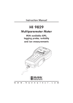
1
Operations & Service Manual
Automated BallWall
System
March 2000 / 17-900280-000
Statement of Intent
This manual is provided to be used by qualified
bowling center personnel. Customer accepts
responsibility for safety training of all personnel
who service and maintain this product.
Automated BallWall System - Operations and Service Manual
© March 2000 by the Brunswick Bowling and Billiards Corporation. All rights reserved.
Past Revisions: July 1999
Reorder Part No. 17-900280-000
Confidential proprietary information. All information contained in this document is subject to change without notice.
Do not reproduce or disclose without the written consent of the Brunswick Indoor Recreation Group.
Brunswick Indoor Recreation Group
Capital Equipment Division
525 W. Laketon Avenue
Post Office Box 329
Muskegon, MI 49443-0329
U.S.A.
231.725.3300
Fax 231.725.3412
Table of Contents
Warranty and Service Policy ............................................................................ 1
Replacement Parts Under the Warranty ....................................................... 1
Federal Communications Commission Class B Equipment .............................. 2
Purpose of This Manual ................................................................................... 3
Safety Precautions ............................................................................................ 4
Recommended Guidelines for Safe Automated Bumpers Bowling .................. 5
Supervision .................................................................................................... 5
Advise ........................................................................................................... 5
Use Foul lights and Buzzers .......................................................................... 5
Prevent Unnecessary Closings of the Bumpers ............................................ 5
Section 1: General Information ..................................................................... 6
System Overview ............................................................................................. 6
General Description of Automation Components ............................................. 8
Actuator Assembly ........................................................................................ 8
Automated Bumper Controller - General Information .................................. 9
LEDs .........................................................................................................13
Fuses .........................................................................................................13
Power Transformer Jumpers (J5 through J8) ...........................................14
System Controller for Stand - Alone Systems ..........................................15
Section 2: Setup and Operations ................................................................. 16
Operational Check of System ..........................................................................16
Automated Bumper System Operation with Frameworx Scorers Control Desk ....................................................................................................17
Turn Automated Bumpers On While Issuing a Lane ...................................17
Enable Automated Bumpers from the Waiting List .....................................17
At the Waiting List Screen ........................................................................17
Turn On Automated Bumpers After Lane Has Been Issued ......................18
Method One ..............................................................................................18
Method Two ..............................................................................................18
Turn Off Automated Bumpers While a Lane is in Use ...............................18
Method One ..............................................................................................18
Method Two ..............................................................................................18
Raising/Resetting Bumpers During an Emergency Control Desk Operation ...............................................................................19
Operations at the Frameworx Scorer .............................................................20
Automated Bumper System Operation - Frameworx Scorer ......................20
Edit Existing Bowler Names at the Scorer ...............................................20
Adding New Bowler Names with Automated Bumpers ..............................20
System Controller - Initial System Setup - Stand Alone Configuration ...........21
Lane Configuration Mode - Stand Alone .....................................................22
Confirm Lane Configuration - Stand Alone .................................................23
Diagnostics Mode - Stand Alone Controller .................................................24
i
Daily System Operation- Stand Alone Configuration ......................................25
Individual Lane Selection ..............................................................................25
Selecting Lane Range ..................................................................................25
Daily System Operation- Stand Alone Configuration - Continued ..................26
Error Messages ............................................................................................26
Resetting Emergency UP Switch Conditions ...............................................26
Section 3: Service, Maintenance and Troubleshooting ............................ 27
Actuator Adjustments ......................................................................................27
Motor Limit Switch Cam - Adjustment for Closing Gutter ..........................27
Adjusting through Access Cover - Cams are Accessible When Gutters are
Closed .......................................................................................................27
Mechanical Linkage - Adjustment for Opening Gutter ................................29
Replacing the LLAN PCB (Part Number 57-300790-000) ............................32
Cable Replacement ..........................................................................................33
Service and Maintenance ................................................................................36
Service Access for Both Gutters Stuck in Closed Position ..........................36
Service Access for Both Gutters Stuck in Open Position ............................37
Maintenance .................................................................................................38
Yearly Maintenance - (20,000 - 40,000 cycles) ........................................38
Every Three Years of Operation (100,000 cycles) ...................................39
Motor Sleeve Replacement .......................................................................40
Motor Replacement ..................................................................................40
Gutter Position Check ..................................................................................42
Inspect and Correct A Drive Pin Interference - Automated
BallWall Systems .............................................................................................45
System Troubleshooting - Automated BallWall ...............................................50
Appendix A - Cables ...................................................................................... 57
ii
Warranty and Service Policy
If any defects in material or workmanship appear during the first three months
after installation, the defective part will be repaired or replaced, at Brunswick’s
option, with no charge to the Customer.
If any defects in material appear during the nine months following the initial three
month warranty period, the defective part will be repaired or replaced, at
Brunswick’s option, with no charge to the Customer for parts. The Customer
must assume all other costs in making the repair or replacement.
All service calls during the first three months of the warranty period, resulting
from the inability of the Customer’s mechanics to perform required adjustments
or maintenance, will be billed directly to the Customer.
Brunswick reserves the right to change the design of any product, but assumes
no responsibility to incorporate such design changes on products already sold.
The warranty applies only to new products installed by Brunswick and extends
only to the original purchaser. Repairs or replacements made by anyone not
approved by Brunswick void the warranty.
Under no circumstances shall the Seller or Manufacturer be liable for loss of
profits or other direct or indirect costs, expenses, losses, or damages arising out
of defects in or failure of parts.
Replacement Parts Under the Warranty
All service parts are F.O.B. the installation site both during and after the warranty period. The price of parts includes delivery by standard means, such as
United Parcel Service (UPS). Any expense resulting from expedited delivery,
such as air freight, will be billed to the Customer.
During the one year period, parts which are faulty due to material or workmanship will be replaced or repaired free of charge only if the old part is properly
identified and turned in for credit. Identify the defective part by attaching a tag
containing the part name and part number. Light bulbs are not covered by the
warranty.
Contact the Warranty Department at 1-231-725-3433.
Automated BallWall Systems Operations and Service Manual
1
Federal Communications Commission Class B Equipment
This equipment has been tested and found to comply with the limits for a class B
digital device, pursuant to part 15 of the FCC rules. These limits are designed to
provide reasonable protection against harmful interference in a residential
installation. This equipment generates, uses and can radiate radio frequency
energy and, if not installed and used in accordance with the instructions, may
cause harmful interference to radio communications. However, there is no
guarantee that interference will not occur in a particular installation. If this
equipment does cause harmful interference to radio or television reception, which
can be determined by turning the equipment off and on , the user is encouraged
to try to correct the interference by one or more of the following measures:
2
•
Reorient or relocate the receiving antenna.
•
Increase the separation between the equipment and receiver.
•
Connect the equipment into an outlet on a circuit different from that to
which the receiver is connected.
•
Consult the dealer or an experienced radio/TV technician for help.
Automated BallWall System Operations and Service Manual
Purpose of This Manual
This manual is designed to provide instructions and guidelines to qualified bowling
center operators and maintenance personnel regarding the automated Ball Wall
system. Operations, servicing, scheduled maintenance and basic troubleshooting
procedures are listed to provide center personnel with the necessary instructions
for maintaining the automated Ball Wall system in the best possible operating
condition.
Equipment problems or issues that are not directly addressed within this manual
should be brought to the attention of the Customer Response Center at 1-800323-8141.
Automated BallWall Systems Operations and Service Manual
3
Safety Precautions
Certain procedures in this manual may require operational checks of the system.
All non-operational electrical work should be done with the power turned off
(power cord unplugged to automatic bumper controller). When operational
checks require electrical power to be turned on, extreme care must be exercised
to avoid contacting electrical components or power sources. Simple steps such
as reinstalling covers, proper static grounding, etc. should be performed to
prevent injury to personnel and/or equipment damage.
Operational checks using the Diagnostic screen for Frameworx scorers should
only be performed if :
• The center personnel are aware the installation or service of equipment is
in process.
• The lane(s) being worked on are placed in an out of service or hold status.
This prevents personnel from inadvertently activating the pinsetter and
issuing a lane.
4
Automated BallWall System Operations and Service Manual
Recommended Guidelines for Safe Automated Bumpers Bowling
Automated Bumper Bowling presents a risk of injury to young children who
attempt to walk on the lane surface and could slip and fall while the automated
bumpers are closing. The following "Operating Guidelines" are provided for
bowling center proprietors, managers and their employees in an effort to minimize this risk to the greatest extent possible while providing an enjoyable bowling experience for young bowlers.
Supervision
Always make sure that parents, youth group sponsors, and/or bowling center
instructors supervise children bowlers.
Advise
1.
Advise children's supervisors and children, of the risk of slipping and
falling if the bowler crosses the foul line and walks on the lane surface.
2.
Advise parents of children's desires to chase balls that have stopped on
the lane.
3.
Advise supervisor and children to call a center employee to retrieve a
ball.
4.
"Bumper Up Switch" - Advise parents, supervisors and employees of its
location and it's use.
Use Foul lights and Buzzers
Keep them on. Advise children and parents of the presence and significance of
the foul line and foul lights. Children are wary of the sound of the buzzers. They
are also sensitive to the loss of score should they create a foul.
Prevent Unnecessary Closings of the Bumpers
1.
Leave the bumpers permanently in the up position when only young
children are bowling.
2.
Assign a younger children lineup (bowling) order when parents and older
siblings are also bowling.
Automated BallWall Systems Operations and Service Manual
5
Section 1: General Information
System Overview
The automated bumper system is an electromechanical system that allows the
user to conveniently raise and lower the gutters on a lane pair from a remote
location. When used with the Frameworx scoring system, the gutters can be
controlled automatically for each bowler from the individual scorers consoles.
The system consists of an actuator assembly (complete with motor) and an
automated bumper controller mounted approximately 27-30' (8.22 - 9.14 m)
from the foul line in the ball return area. An emergency up switch mounted on
the ball return capping next to the foul line, provide a means of raising the gutters
in the event of an emergency.
When installed as a Stand-Alone system (no Frameworx scorers), a system
controller is placed at the Control Desk and allows the user to raise and lower
selected lanes with automated bumpers. Refer to Figure 1.
6
Automated BallWall System Operations and Service Manual
(1)
(2)
(3)
(4)
(5)
(6)
(7)
AUTOMATED BUMPER CONTROLLER
RECEPTACLE
ACTUATOR
EMERGENCY UP SWITCH
CONTROL DESK
FOUL LINE
SYSTEM CONTROLLER
Figure 1. Overview - Stand Alone Configuration
Automated BallWall Systems Operations and Service Manual
7
General Description of Automation Components
Actuator Assembly
The actuator assembly consists of an actuator motor and sleeve attached to each
gutter tube through gutter pivot assemblies and connector rods. As the motor
turns, a worm gear inside the sleeve rotates causing the sleeve to move forward
or backward depending on the direction the motor is rotating. When the sleeve
moves forward away from the motor, it causes the connector rods to pull on
pivot assemblies raising the gutters. If the sleeve moves backwards toward the
motor, the connector rods push the pivot assemblies causing the gutter to lower.
Limit switches on the motor control the distance the gutters will open or close.
Refer to Figure 2.
Figure 2. Actuator Assembly
(1)
(4)
(7)
(10)
(13)
8
ACTUATOR ASSEMBLY
HITCH PIN
GUTTER PIVOT ASSEMBLY
ANCHOR
MOTOR
(2)
(5)
(8)
(11)
LEFT-HAND CONNECTING ROD
END VIEW
3/8-16 X 3/4" HEX HEAD CAP SCREW
SLEEVE
Automated BallWall System Operations and Service Manual
(3)
(6)
(9)
(12)
CLEVIS PIN
MOUNTING PLATE
3/8" WASHER
RIGHT-HAND CONNECTING ROD
Automated Bumper Controller - General Information
Commonly referred to as the control “Box”, the automated bumper controller
consists of a single printed circuit board (PCB). The main function of this PCB is
to supply and control power to the actuator motors of the lane pair.
The PCB determines when to raise or lower the gutters based on information it
receives from the control desk's System Controller (Stand-Alone installations) or
I/O PCB (Frameworx scorer installations).
The emergency up switch mounted on the ball return capping, overrides any
information received from the System Controller or I/O PCB causing the automated bumper controller to raise the gutters. Refer to Figure 3.
Figure 3. Automated Bumper Controller PCB
(1)
(4)
(7)
(10)
CONTROLLER PCB
COMMUNICATIONS OUT
EMERGENCY UP LED
GUTTER UP LEDS
(13) ACTUATOR MOTOR OUTPUT RIGHT
LANE
(2)
(5)
(8)
(11)
EMERGENCY UP SWITCH INPUT
TERMINATION JUMPER
CONFIGURATION DIP SWITCHES
GUTTER DOWN LEDS
(14) MOTOR FUSES
(3)
(6)
(9)
(12)
(15)
COMMUNICATIONS IN
POWER LED
POWER TRANSFORMER JUMPERS
ACTUATOR MOTOR OUTPUT LEFT
LANE
HEARTBEAT LED
The functions of the automated bumper controller PCB are:
•
Actuator Motor Output - Left Lane (J10) - Terminal block used to
output voltage to the left lane actuator motor. The motor should be wired
according to the color-coded label located next to the terminal block.
Automated BallWall Systems Operations and Service Manual
9
•
Actuator Motor Output - Right Lane (J11) - Terminal block used to
output voltage to the right lane actuator motor. The motor should be
wired according to the color-coded label located next to the terminal
block.
•
Communication In (J3) - Input for communication entering the PCB.
On the first lane pair for Stand-Alone configurations, this information
comes from the system controller located at the control desk.
Refer to Figure 3. For additional lane pairs in a Stand-Alone system the
cable comes from the prior lane pair bumper controller. Refer to
Communications Out (J4). For installations with Frameworx scorers,
the input data to J3 is sent from the I/O PCB - J2.
NOTE: A LLAN Breakout PCB is mounted in either the lane group processor, or Frameworx scorer console, and allows easy cabling to the existing
Frameworx local LAN.
•
Communication Out (J4) - This connection allows the information
entering the PCB at J3 to continue out of the PCB to other devices. For
stand alone systems, the J4 port attaches to the next lane pair’s automated bumper controller. If automated bumper controller is for the last
lane pair with automated bumpers, a jumper (terminator) must be
installed on pins 2 and 3 of JP1. Refer to Figure 4 Termination Jumper
(JP1).
•
Emergency Up Switch Connectors (J1 and J2) - When activated, the
emergency up switch for that specific lane pair, triggers the controller
PCB and overides any current command or condition to immediately
raise the gutters on both lanes. J1 port is for left lane gutters and J2 is
for right lane gutters.
•
Termination Jumper (JP1) - The termination jumper is used to terminate the communications line for the last lane pair in a Stand-Alone
system. Set the jumpers as shown in Figure 4.
INSTALLATION LOCATION
Frameworx Scorers
Stand-Alone (all but last lane pair)
Stand-Alone (last lane pair only)
Figure 4. Termination Jumper (JP1).
10
Automated BallWall System Operations and Service Manual
SETTINGS
•
DIP Switch Configuration - These two-position ON-OFF switches
provide lane address identification to the controller PCB. When Frameworx scorers are installed, ALL DIP switches must be set to OFF. For
Stand-Alone systems, the DIP switches MUST be set as listed in
Figure 5.
Automated BallWall Systems Operations and Service Manual
11
NOTE: For installations with
Frameworx scorers all switches
must be "OFF".
Lane No.
SW 1
SW 2
SW 3
SW 4
SW 5
SW 6
SW 7
SW 8
1-2
ON
OFF
OFF
OFF
OFF
OFF
OFF
OFF
3-4
ON
ON
OFF
OFF
OFF
OFF
OFF
OFF
5-6
ON
OFF
ON
OFF
OFF
OFF
OFF
OFF
7-8
ON
ON
ON
OFF
OFF
OFF
OFF
OFF
9-10
ON
OFF
OFF
ON
OFF
OFF
OFF
OFF
11-12
ON
ON
OFF
ON
OFF
OFF
OFF
OFF
13-14
ON
OFF
ON
ON
OFF
OFF
OFF
OFF
15-16
ON
ON
ON
ON
OFF
OFF
OFF
OFF
17-18
ON
OFF
OFF
OFF
ON
OFF
OFF
OFF
19-20
ON
ON
OFF
OFF
ON
OFF
OFF
OFF
21-22
ON
OFF
ON
OFF
ON
OFF
OFF
OFF
23-24
ON
ON
ON
OFF
ON
OFF
OFF
OFF
25-26
ON
OFF
OFF
ON
ON
OFF
OFF
OFF
27-28
ON
ON
OFF
ON
ON
OFF
OFF
OFF
29-30
ON
OFF
ON
ON
ON
OFF
OFF
OFF
31-32
ON
ON
ON
ON
ON
OFF
OFF
OFF
33-34
ON
OFF
OFF
OFF
OFF
ON
OFF
OFF
35-36
ON
ON
OFF
OFF
OFF
ON
OFF
OFF
37-38
ON
OFF
ON
OFF
OFF
ON
OFF
OFF
39-40
ON
ON
ON
OFF
OFF
ON
OFF
OFF
41-42
ON
OFF
OFF
ON
OFF
ON
OFF
OFF
43-44
ON
ON
OFF
ON
OFF
ON
OFF
OFF
45-46
ON
OFF
ON
ON
OFF
ON
OFF
OFF
47-48
ON
ON
ON
ON
OFF
ON
OFF
OFF
49-50
ON
OFF
OFF
OFF
ON
ON
OFF
OFF
51-52
ON
ON
OFF
OFF
ON
ON
OFF
OFF
53-54
ON
OFF
ON
OFF
ON
ON
OFF
OFF
55-56
ON
ON
ON
OFF
ON
ON
OFF
OFF
57-58
ON
OFF
OFF
ON
ON
ON
OFF
OFF
59-60
ON
ON
OFF
ON
ON
ON
OFF
OFF
61-62
ON
OFF
ON
ON
ON
ON
OFF
OFF
63-64
ON
ON
ON
ON
ON
ON
OFF
OFF
65-66
ON
OFF
OFF
OFF
OFF
OFF
ON
OFF
67-68
ON
ON
OFF
OFF
OFF
OFF
ON
OFF
69-70
ON
OFF
ON
OFF
OFF
OFF
ON
OFF
71-72
ON
ON
ON
OFF
OFF
OFF
ON
OFF
73-74
ON
OFF
OFF
ON
OFF
OFF
ON
OFF
75-76
ON
ON
OFF
ON
OFF
OFF
ON
OFF
77-78
ON
OFF
ON
ON
OFF
OFF
ON
OFF
79-80
ON
ON
ON
ON
OFF
OFF
ON
OFF
Figure 5. DIP Switch Settings (Stand - Alone)
12
Automated BallWall System Operations and Service Manual
LEDs
Several LEDs are located on the controller PCB to indicate various operating
functions/conditions. Refer to Figure 3 for LED locations on the controller PCB.
The LED functions are:
•
Gutter Up LEDs (D11, D13) - These LEDs light to indicate that the
gutters are in the UP position. LED D11 is for left lane and D13 is for
right lane gutters.
•
Gutter Down LEDs (D12,D14) - These LEDs light to indicate that the
gutters are in the DOWN position. LED D12 is for left lane and D14 is
for right lane gutters.
•
Emergency UP LEDs (D4, D5) - These LEDs light whenever the
emergency up switch is used to raise the gutters.
•
Power LED (D3) - This LED lights to indicate the presence of DC 12V
power.
•
Heartbeat LED (D10) - This LED flashes to indicate the presence of
communication to the Frameworx scorer or the system controller in a
stand alone system. When communication is present, the LED will light
in a FLASH, FLASH, PAUSE sequence.
Fuses
There are three fuses located on the controller PCB. Refer to Figure 3.
•
Power Fuse - A .25 amp main power fuse.
•
Motor Fuses - Fuses for the actuator motors. Fuses are field installed
during installation based on input voltage. 115VAC = 1.6 amp,
230VAC= .8 amp
NOTE: Fuse F2 is for right lane actuator motor and F3 is for left lane
actuator motor.
Automated BallWall Systems Operations and Service Manual
13
Power Transformer Jumpers (J5 through J8)
These jumper terminals allow the user to setup the controller for 115VAC or 230
VAC input. Refer to Figure 6 for jumper locations for 115VAC power source
and Figure 7 for 230VAC power source.
(1)
(2)
(3)
(4)
CONTROLLER PCB
115V JUMPER CONFIGURATION
ATTACH TO ENCLOSURE
RECEPTACLE
Figure 6. Power Jumper Settings - 115VAC
(1)
(2)
(3)
(4)
CONTROLLER PCB
230V JUMPER CONFIGURATION
ATTACH TO ENCLOSURE
RECEPTACLE
Figure 7. Power Jumper Settings - 230 VAC
14
Automated BallWall System Operations and Service Manual
System Controller for Stand - Alone Systems
A System Controller is located at the Control Desk in centers not equipped with
Frameworx scoring systems. The controller allows the desk operator to raise or
lower the gutters on a lane(s). Refer to Figure 8.
(1)
(2)
(3)
(4)
(5)
(6)
(7)
POWER IN
POWER SWITCH
SHIFT DATA PORT
SERIAL PORT
CONTRAST
AUDIO IN (NOT USED)
AUDIO OUT (NOT USED)
Figure 8. System Controller - Rear Connector Ports and Controls
The controller functions/features are:
•
Power In - Connection for the main power for the controller.
•
Power Switch - Main Power, On/Off toggle switch.
•
Shift Data Port - Not used.
•
Serial Port - Connection for communication cable going to the automated bumper controller (first lane pair).
•
Display Contrast - Rotate this control to adjust the LCD screen for best
visibility.
•
Audio - Not used.
Automated BallWall Systems Operations and Service Manual
15
Section 2: Setup and Operations
Operational Check of System
NOTE: The following steps are performed at the Frameworx scorer and
require Frameworx Scorer software version 4.1.8 or higher. They are basic
commands and/or status messages used to verify system operation after
installation or during system troubleshooting. General bumper system
operation is listed under the "Automated Bumper - Control Desk".
1.
At the Frameworx scorer maintenance menu: Select "Enter Diagnostics" menu, and press OK. Enter password and press OK.
NOTE: The "Frameworx Scorer Service Manual" part number 57-900351000 lists detailed steps on entering maintenance/diagnostics menus at the
Frameworx Scorer.
2.
Select "Bumpers Configuration" and press OK.
3.
Choose "Left Lane or Right Lane Configuration" and press OK.
4.
Select "Enable Bumpers" and press OK.
5.
Scroll down to the "Close Channels" option and press OK. The gutters
should close if they are presently open.
NOTE: The terms gutters and channels are interchangeable.
6.
Select "Get Switch and Motor Status" option and press OK.
On the status screen, verify that the message, "The Channels are Fully
Closed" appears on the screen. If not, the actuator motor limit switch
cam for the closed position is not made. See "Actuator Adjustments"
for required adjustments procedure.
7.
Select OK to close out of screen.
8.
Scroll down to "Open Channels" and press OK. The gutters should
open.
9.
Select "Get Switch and Motor Status" option and press OK.
On the status screen, verify that the message, "The Channels are Fully
Opened" appears on the screen. If not, the actuator may require a
mechanical linkage adjustment. See "Actuator Adjustments" for
required adjustment procedure.
10.
Make adjustments and recheck switch status until both switches report
fully opened and closed states as applicable.
NOTE: Reset switch status before each check.
16
Automated BallWall System Operations and Service Manual
Automated Bumper System Operation with Frameworx Scorers - Control Desk
Turn On Automated Bumpers While Issuing a Lane
NOTE: Perform the following steps at the Control Desk CMS terminal:
1.
Select LANE NUMBER(S) for automated bumper system.
2.
Press LANE ON key.
3.
While "check in" screen is displayed, press the é key. The automated
bumper system is now available to the bowlers on that lane. Press the é
a second time to disable automated bumpers.
NOTE: The status of the automated bumpers is displayed by a “W” in the
RATE box while the "check in" screen is displayed. When the letter “W” is
present, automated bumpers are available to the bowlers on the selected
lane or lane range. Automated bumpers will need to be enabled for the
appropriate bowlers as names are entered at the automatic scorer. Names
that were previously entered, entered via the Waiting List, entered via
“Download Open Party” or entered via “View/Correct Scores” will have to
be edited at the automatic scorer to activate for the appropriate bowler(s).
Enable Automated Bumpers from the Waiting List
At the Waiting List Screen
1.
Press "A" to add a party to the waiting list.
2.
Type the party name and press ENTER.
3.
Type the number of bowlers in the party and press ENTER.
4.
Use the arrow keys to highlight the scoring unit available and press
ENTER.
5.
Use the arrow keys to highlight "Bumpers" on the Centers Services List.
Press ENTER to select bumpers. (An asterisk will display when
bumpers are selected.) Pressing ENTER a second time deselects
bumpers. Press ENTER SCREEN when all of the desired Center
Services have been selected.
6.
Proceed with step 6 as listed in the Control Desk Operations Guide
57-900355-000 pages 3-2 through 3-3.
Automated BallWall Systems Operations and Service Manual
17
Turn On Automated Bumpers After Lane Has Been Issued
NOTE: Operators can choose one of two methods to turn on the automated bumpers after a lane has been issued.
Method One
1.
Press SCORER STATUS key.
2.
Enter the lane number and/or lane range and press the é key.
3.
The prompt “Lift bumpers for everyone? Y/N” will appear.
4.
If Y (yes) is selected, ALL bowler names for that lane number/lane
range will have automated bumpers activated.
5.
If N (no) is selected, the appropriate bowler name(s) will have to be
edited at the scorer.
Method Two
1.
Enter lane number(s) and press ADJUST key.
2.
With "ADJUST" screen displayed, press é key. Bumpers are now
available for bowler(s) on this lane.
3.
Press ADJUST key again to exit.
Turn Off Automated Bumpers While a Lane is in Use
NOTE: Operators can choose one of two methods to turn off the automated bumpers while a lane is in use.
Method One
1.
To disable the automated bumper system:
a. Enter the lane number or lane range.
b. Press U key and then the é key. Automated bumpers are no longer
available for that lane/lane range.
Method Two
18
1.
Enter lane number(s) and press "ADJUST" key.
2.
With adjust screen displayed, press the é key. Bumpers are no longer
available for bowler(s) on this lane.
3.
Press adjust key again to exit.
Automated BallWall System Operations and Service Manual
Raising/Resetting Bumpers During an Emergency - Control Desk
1.
EMERGENCY UP - Enter lane number or lane range and press é key.
2.
To reset bumpers after an Emergency UP command has been given OR
the Emergency UP switch has been pressed:
a. Enter lane number or lane range and press é key.
b. At the prompt, “Bumpers are in emergency up. Do you want to turn
off emergency up? Y/N". Enter Y to lower bumpers and return to
normal operation. If N is entered, bumpers will remain in the emergency UP position.
Automated BallWall Systems Operations and Service Manual
19
Operations at the Frameworx Scorer
Automated Bumper System Operation - Frameworx Scorer
Edit Existing Bowler Names at the Scorer
1.
Press BOWLER and then EDIT.
2.
Use the é and ê keys to highlight bowler name to be edited and press
OK.
3.
Press the é or ê key to highlight AUTOMATED BUMPERS mode.
4.
Use ç or è key to turn bumper on or off for that bowler. Press OK
when finished.
Adding New Bowler Names with Automated Bumpers
20
1.
Press BOWLER and then ADD.
2.
Enter bowler name and press ê key.
3.
Use ç or è to select left or right-handed coach display and then press
ê key.
4.
Use ç or è key to select (turn on) automated bumpers for specified
bowler name.
5.
Press DONE or NEXT to add another bowler with automated bumpers.
Automated BallWall System Operations and Service Manual
System Controller - Initial System Setup - Stand Alone Configuration
After completing the installation of automated bumper system components, the
system controller at the control desk must be programmed to specify which and
how many lanes within the center have automated bumpers installed.
Perform the following steps:
1.
Place toggle switch on rear of unit up (ON) position. Refer to Figure 9
for switch/button locations.
Figure 9. System Controller - Stand Alone Configuration
(1) SELECT "ENTER" KEY
(2) LANE NUMBER SCROLL DOWN KEY
(3)
(4) LANE NUMBER SCROLL UP KEY
(7) LOWER CHANNEL KEY
(5) "YES" KEY (BALLWALL INSTALLED?)
(6)
2.
"NO" KEY (BALLWALL
INSTALLED?)
RAISE CHANNEL KEY
On the LCD display, the prompt, “ENTER FIRST LANE WITH BALL
WALL: 01” will appear.
Automated BallWall Systems Operations and Service Manual
21
3.
Use the4(up) arrow key to identify the the first lane number with
automated BallWall installed.
4.
Press SELECT key. The last lane prompt is now displayed.
5.
Use the4(up) and 3 (down) arrow keys to identify the last lane
number with automated BallWall installed.
6.
Press SELECT to accept the lane number data.
Lane Configuration Mode - Stand Alone
NOTE: It is initially assumed that all lanes from the start to the end lane
will have the automated BallWall installed - all lanes will be set to “Y” (YES
- BallWall installed). If this is the case, pressing SELECT will end the lane
configuration mode immediately.
Those lanes that do NOT have ball wall must be identified as follows:
7.
With the prompt “ BALL WALL LN 00? -Y PRESS SELECT TO
END” displayed,
a. Use the4(up) and3(down) arrow keys to scroll through the lane
numbers.
b. Press SELECT when desired lane appears.
c. Press4(yes) or3(no) key to identify each specific lane.
d. To change from a no BallWall installed status back to yes (BallWall
installed), press the4key.
e. Press SELECT to end the lane configuration mode.
22
Automated BallWall System Operations and Service Manual
Confirm Lane Configuration - Stand Alone
To verify that the lane configuration data has been entered correctly, the following prompt will appear:
“SETUP COMPLETE? UP = YES DOWN=NO”
1.
Press4(YES) key to confirm that the setup is complete; the normal
(default) mode is then displayed on the LCD.
2.
If3(NO) is pressed, ALL setup data is cleared, and the setup will start
over again with the prompt ‘ENTER FIRST LANE WITH BALLWALL:
01".
NOTE: If the setup data is corrupted or lost, it will be cleared and the
initial setup prompts will be displayed again. The operator MUST perform
the steps listed under “System Controller - Initial System Setup” again.
In addition, the operator may change current configuration of lane (i.e.
add/remove bumper mode) using same steps.
NOTE: To reconfigure the lanes with automation, press and hold the 5
key until the menu returns to the setup screen.
Automated BallWall Systems Operations and Service Manual
23
Diagnostics Mode - Stand Alone Controller
The diagnostics mode is designed to allow BallWall system installers and/or field
service personnel to make adjustments and check status of switch on the actuator
controllers and actuators. Only one lane at a time is affected under the diagnostics
mode.
1.
Press and hold SELECT key for five seconds to access the diagnostics
mode.
2.
The currently selected lane is displayed:
"DIAG LN01 COARSE
*OPEN = 0 CLOSE = 1"
3.
Press4key to scroll lane number up or3key to scroll lane number down.
Lane numbers without automatic ball wall installed are automatically
skipped.
4.
Press SELECT key to toggle between full open/close, coarse and fine
adjustment modes.
5.
Press5arrow key and continue to press and release to move channel UP
in the selected increments.
6.
Press6key and press repeatedly to move channel DOWN in the selected
increments.
NOTE: While in diagnostics mode, the opening and closing status messages
are not displayed.
7.
24
Press and hold the SELECT key for five seconds to disable and exit the
diagnostics mode.
Automated BallWall System Operations and Service Manual
Daily System Operation- Stand Alone Configuration
Initially, the default lane will be the first lane in the center that has automated
BallWall installed and the following prompt is displayed:
“BALLWALL LANE O1”
Individual Lane Selection
1.
Press8key to scroll up orwto scroll down until desired lane number is
displayed.
2.
Press5arrow key to raise channels (bumpers) for specified lane. Press
6key to lower channels for specified lane.
Selecting Lane Range
1.
With prompt “BALLWALL LANE O1” displayed, press SELECT key.
Two up arrows are shown on LCD display beneath starting lane number.
2.
Use8key to scroll up until desired starting lane is displayed.
3.
Press SELECT key again to specify the ending lane number. Two
arrows are displayed beneath the current (ending) lane number.
4.
Press8or w keys to scroll up or down until desired ending lane is
displayed.
5.
Press5key to raise channels for selected lane range. Press 6key to
lower channels for selected lane range.
NOTE: Starting lane range may never be less than the first lane in the
center that has automated BallWall installed and ending lane range not
greater than last lane with BallWall. Pressing and holding either the 56
keys for more than 0.5 seconds will scroll the starting lane lumber at a rate
of 1 lane every 0.5 seconds until the maximum or minimum lane has been
reached. Pressing the SELECT key a third time will return to the default
prompt allowing the operator to select one lane at a time.
Lanes that do NOT have automated BallWall installed are automatically
skipped over when selecting lane range.
If a selected range of lanes includes lanes that are not all in the same state
(opened or closed), pressing the5key will raise all channels that are not
currently raised. Pressing the6key will lower all channels that are not
currently lowered.
Automated BallWall Systems Operations and Service Manual
25
Daily System Operation- Stand Alone Configuration - Continued
Error Messages
There are five error messages that may appear on the LCD display;
•
•
•
•
•
Could not open channel
Could not close channel
Communication error
Invalid Switch State
COM LINE DOWN - (All communication with ALL actuator
controllers has been lost)
These messages appear to alert the operator of the displayed condition. Refer to
“Troubleshooting” section of this manual for error description and corrective
actions.
Resetting Emergency UP Switch Conditions
When the emergency UP switch is pressed on any of the lanes, it overrides any
commands from the system controller and immediately opens the channels on the
affected lane. The following prompt appears on the controller LCD display:
“EMERGENCY UP 01
PRESS SEL TO CLR”
1.
26
Press SELECT key to reset an emergency UP condition. Normal
BallWall operation is restored on the affected lane.
Automated BallWall System Operations and Service Manual
Section 3: Service, Maintenance and Troubleshooting
Actuator Adjustments
Motor Limit Switch Cam - Adjustment for Closing Gutter
Adjusting through Access Cover - Cams are Accessible When Gutters are Closed
WARNING: USE CAUTION when adjusting the motor limit switch cam on
the actuator motors as power is required to perform this procedure when
using Frameworx scorers. The lane(s) being adjusted should be placed out
of service at control desk until adjustments are finished. Failure to use
caution may result in injury to personnel!
1.
At the control desk with "Lane Status" screen displayed:
a. Press lane number and "Hold" key at the same time. Lane is now
out of service.
b. Press lane number and "Hold" key at the same time again to make
lane available for use.
2.
Remove the screw securing black plastic cap on actuator motor.
3.
Locate the two limit switch cams. The inner switch cam is for the
OPEN (gutter) position and is NOT adjustable. Refer to Figure 10 for
switch cam location.
Automated BallWall Systems Operations and Service Manual
27
Figure 10. Adjust Limit Switch Cams
(1) OPEN (FIXED) CAM
(4) SWITCH NOT CLOSED
(2) LIMIT SWITCH
(5) LOBE
(3)
(6)
CLOSE (ADJUSTABLE) CAM
SWITCH CLOSED
NOTE: Steps 4 through 6 below pertain to a partially-closed gutter condition where access to the motor limit switch cam is available through an
access cover hole on the return capping. The gutter should be in the down
position before performing step 4.
4.
With the gutter in the down position, rotate the outer (close) switch cam
either direction until the lobe on the switch cam contacts the switch
(switch is made). Refer to Figure 10.
5.
Open and then close the gutters for applicable lane as follows:
a. Frameworx Scorer - If scorers are installed see "Operational
Check of System" paragraph to open/close bumpers.
b. Automated Bumpers Remote Control Box - When Frameworx
scorers are not installed yet, use this device (supplied) to raise/lower
bumpers. See "Gutter Position Check" paragraph to use remote
control box.
6.
Verify that bumper is in CLOSED position:
a. Frameworx Scorer - Select "Get Switch and Motor Status" from
"Diagnostics " Menu.
28
Automated BallWall System Operations and Service Manual
b. Automated Bumper Remote Control Box - Check "Gutter
Down" LED on the automated bumper controller PCB. Refer to
Figure 3.
7.
Observe gutter movement. The gutter should close beneath the lane
surface.
8.
Repeat steps 4-7 above as necessary until gutter closes completely. The
switch cam may require slight adjustments in either direction in order to
cause the gutter to fully close.
9.
Reinstall black plastic cap on actuator motor.
Mechanical Linkage - Adjustment for Opening Gutter
The actuator motor limit "OPEN" switch cam is preset by the manufacturer to
open the gutters to the proper position and is not adjustable. It is recommended to
use the factory - adjusted setting whenever possible! However, if the factory
setting results in a partially open condition, a mechanical linkage adjustment may
be necessary.
NOTE: It is important that the OPEN motor limit switch cam is “closed”
(Figure 10) BEFORE making any adjustment to increase or decrease stroke
of actuator sleeve.
WARNING: Steps 1 through 6 below should be done with the power
disconnected to the automated bumper controller.
1.
Unplug power cord from the automated bumper controller.
2.
Disconnect the clevis pins from the connecting rods on both ends of
actuator. Refer to Figure 11.
Automated BallWall Systems Operations and Service Manual
29
Figure 11. Mechanical Linkage Adjustment
(1)
(4)
(7)
(10)
TURN COUNTER CLOCKWISE
JAM NUT
MOTOR ADAPTER CLEVIS
MOUNTING PLATE
(2)
(5)
(8)
(11)
HITCH PIN
CLEVIS PIN
MOTOR ADAPTER MOUNT PIN
HEX HEAD SCREW AND
LOCKWASHERS
(3)
(6)
(9)
(12)
ROD END
LEFT-HAND CONNECTING ROD
ACTUATOR MOTOR
ACTUATOR SLEEVE
3.
Remove hex head screws securing actuator base to the floor.
4.
Slide actuator toward the open gutter to allow access to mechanical
linkages.
a. Remove motor adapter mount pin from motor adapter clevis. Refer
to Figure 11.
b. Slide connecting rod away from actuator sleeve.
NOTE: It is important that the OPEN motor limit switch cam is “made”
(Figure 10) BEFORE making any adjustment to increase or decrease stroke
of actuator sleeve.
NOTE: Do not adjust the sleeve more than 1" (25 mm) in either direction.
If more than 1" (25 mm) is required, perform mechanical linkage adjustments.
30
Automated BallWall System Operations and Service Manual
c. Grasping sleeve, rotate sleeve counterclockwise (CCW) to increase
open stroke. Rotate sleeve clockwise (CW) to decrease open
stroke. Refer to Figure 11.
NOTE: Make sure drive screw does NOT rotate; only the sleeve.
d. Reconnect the motor adapter clevis into the actuator sleeve and
install pin.
5.
Align actuator base with concrete fastener holes and install hex head
screws.
6.
Reconnect clevis pins to connecting rods on both ends of actuator.
7.
Plug power cord in for the automated bumper controller.
8.
Perform operational check of system (see “Operational Check of
System” for procedure).
9.
If gutters still do not open fully, an adjustment to the mechanical linkage
on connecting rod(s) may be required.
a. Remove hitch pin and clevis pin from connecting rod end.
b. Rotate connecting rod end to lengthen or shorten the rod to clevis
distance. Refer to Figure 11.
c. Reinstall the clevis pin and secure with hitch pin.
d. Check gutters opening and closing movement by performing steps
under “Operational Check of System”.
10.
If further adjustment(s) cannot be done to mechanical linkages, loosen
the three mount bolts securing mounting base plate to the floor and move
actuator within the slots of mounting base plate. Tighten three mount hex
head cap screws once desired position is obtained.
Automated BallWall Systems Operations and Service Manual
31
Replacing the LLAN PCB (Part Number 57-300790-000)
If it becomes necessary, replace the LAN breakout PCB within the Frameworx
scorer or lane group processor (LGP) following instructions below. Refer to
Figure 12.
Figure 12. Replacing Breakout Local LAN PCB
(1) POWER CHASSIS
(4) RECONNECT LLAN CABLE
32
(2) LLAN BREAKOUT PCB
(3)
RECONNECT LANE CABLE
1.
Unplug the two cable connections to the LLAN breakout PCB.
2.
Loosen two screws securing LLAN breakout PCB to scorer or LGP
chassis and remove PCB.
3.
Install new breakout LLAN PCB (part number 57-300790-000, package
number 17-860787-000).
4.
Reinstall two screws to secure PCB.
5.
Plug existing LAN cable connection into J2 port of LLAN breakout
PCB and the lane cable connector into J1 port of the LLAN breakout
PCB. Refer to Figure 12.
Automated BallWall System Operations and Service Manual
Cable Replacement
It may become necessary to replace a cable in the automated bumper system.
Refer to Figures 13, 14, and 15 for the basic cable routing and connections.
NOTE: It is critical that cable routing beneath the lanes does NOT interfere with the ball return path or moving automation components.
(1)
(2)
(3)
(4)
(5)
(6)
(7)
(8)
(9)
(10)
(11)
SYSTEM CONTROLLER
POWER
SERIAL PORT
17-300235-000 FRONT DESK
CONTROLLER TO CONTROLLER
CABLE ASSEMBLY
AUTOMATED BUMPER
CONTROLLER PCB
17-300234-000 AUTOMATED
BUMPER CONTROLLER TO
AUTOMATED BUMPER
CONTROLLER (DAISY CHAIN)
CABLE ASSEMBLY
TO J3 OF NEXT LANE PAIR
AUTOMATED BUMPER
CONTROLLER OR TERMINAL J4
TO MOTOR
17-300284-000 AUTOMATED
BALLWALL EMERGENCY SWITCH
CABLE ASSEMBLY
POWER RECEPTACLE
EMERGENCY UP SWITCH
Figure 13. Stand-Alone Cable Routing and Connections
Automated BallWall Systems Operations and Service Manual
33
(1)
(2)
(3)
(4)
(5)
(6)
(7)
(8)
(9)
(10)
FRAMEWORX LGP OR SCORER
I/O PCB
LLAN BREAKOUT PCB
EXISTING LAN CABLE
17-300256-000 AUTOMATED
BUMPER LANE CABLE ASSEMBLY
AUTOMATED BUMPER CONTROLLER
TO MOTOR
17-300284-000 AUTOMATED
BALLWALL EMERGENCY SWITCH
CABLE ASSEMBLY
EMERGENCY UP SWITCH
POWER RECEPTACLE
Figure 14. Frameworx Cable Routing and Connections
34
Automated BallWall System Operations and Service Manual
Figure 15. Stand - Alone Daisy Chain Cabling
(1) AUTOMATED BUMPER CONTROLLER PCB (2) LAST AUTOMATED BUMPER
CONTROLLER PCB
(4) JUMPER ON PINS 2 AND 3 OF JP1
(5) 17-300235-000 FRONT DESK
CONTROLLER TO CONTROLLER
CABLE ASSEMBLY
(3)
(6)
17-300234-000 AUTOMATION
CONTROL BOX CABLE ASSEMBLY
TO SYSTEM CONTROLLER
Automated BallWall Systems Operations and Service Manual
35
Service and Maintenance
Service Access for Both Gutters Stuck in Closed Position
To gain access to the BallWall automation components when the gutters are
stuck in the closed positions, perform the following steps to remove the actuator
from beneath the lanes:
1.
Remove the section of return capping or the access cover (metal
capping) to gain access to automation components.
2.
Disconnect pin on the closest gutter pivot to opening.
3.
Manually open gutter that has been disconnected from actuator and slide
bumper curtains out of way to expose automation components.
4.
Disconnect power from automated bumper controller and install gutter
"open" safety pins. Refer to Figure 16.
(1) SAFETY PIN
Figure 16. Install Safety Pins
5.
Remove the rear pin that connects motor to base of actuator.
6.
Manually open gutter on division side and install "open" safety pin.
7.
Slide bumper curtains away on opposite side of the lane.
8.
Remove the second pin securing the motor to base of actuator and lift
actuator from beneath the lanes.
NOTE: The motor will slide away from the base once the second pin is
removed. With the actuator removed from beneath the lanes, the gutters
may be manually opened or closed as needed to allow for bumper use. If
service or replacement is to be delayed, slide bumper curtains back into
position on the gutters.
9.
36
Visually inspect/check actuator following steps in this section to determine cause of failure. Repair or replace components as needed.
Automated BallWall System Operations and Service Manual
Service Access for Both Gutters Stuck in Open Position
To gain access to the Ballwall automation components when the gutters are
stuck in the open positions, perform the following steps to remove the actuator
from beneath the lanes:
1.
Install "open" safety pins (part number 17-300189-000) provided with
BallWall installation kit. Refer to Figure 17.
(1) SAFETY PINS
Figure 17. Install Safety Pins
2.
Slide both curtains back to expose gutter pivot assemblies.
3.
Remove pivot pins and retain for reuse.
4.
Reposition curtains for manual operation.
NOTE: With the actuator removed from beneath the lanes, the gutters may
be manually opened or closed as needed to allow for bumper use. If
service or replacement is to be delayed, slide bumper curtains back into
position on the gutters.
Automated BallWall Systems Operations and Service Manual
37
Maintenance
The following items are listed to assist you in properly indentifying and correcting
worn or defective automation parts.
Yearly Maintenance - (20,000 - 40,000 cycles)
1.
Open gutters and install safety pins to prevent gutter from closing (part
number 17-300189-000) provided with BallWall installation kit.
WARNING: The lane(s) being serviced should be placed out of service at
the control desk until servicing is finished. Failure to deactivate lane(s)
may cause injury to personnel!
2.
At control desk with "Lane Status" Screen displayed:
a. Press lane number, and "HOLD" keys at the same time, lane is now
out of service.
b. Press lane number, and "HOLD" keys at the same time again to
make lane available for use.
3.
Remove bumper curtains from both gutters.
4.
Lightly apply pivot grease (part number 11-676306-000) to each pivot
spring. Remove any excess grease from pivot springs. Refer to
Figure 18.
(1) PIVOT ROD ASSEMBLY
Figure 18. Lightly Grease Each Pivot Spring
38
5.
With gutters open, apply a small amount of motor grease (part number
11-676307-000) to the exposed threads of motor worm gear. Wipe off
any excess grease.
6.
Check actuator mount screws for proper tightness; tighten as needed.
7.
Remove safety pins.
Automated BallWall System Operations and Service Manual
8.
Open and close gutters 3-5 times to evenly distribute grease on motor
worm gear.
9.
Open and close gutters several times, have an individual located at
SAFEST possible point next to unit. Listen for excessive noise or
observed vibration during operation.
10.
Visually inspect each accessible pivot point for evidence of abnormal
wear or damage.
11.
Physically check that gutter pivot assemblies are still securely attached
to gutter tubes.
12.
Visually inspect bumper curtains for excessive wear or damage; replace
curtains as needed.
Every Three Years of Operation (100,000 cycles)
1.
Open gutters and install safety pins to prevent gutter from closing.
2.
Remove the bumper curtains and set aside.
3.
Disconnect gutter pivot pins from actuator links. Mark position of
mounting base on concrete.
4.
Remove the actuator base mount screws from the floor.
CAUTION: Use care when removing actuator from beneath lanes to prevent
damage to the motor to controller cable.
5.
Slide actuator toward return side of lane and remove actuator from
beneath lanes.
6.
With actuator above lanes, cycle unit several times and visually inspect
for normal operation.
7.
Inspect grease around the motor worm gear for presence of hard
particles (plastic chips or splinters from the plastic sleeve). If hard
particles are present, order a new replacement sleeve (part number 17860780-000) and replace sleeve using instructions under “Motor Sleeve
Replacement” paragraph.
NOTE: Unit may need to be reassembled and placed back into operation
until replacement sleeve is available.
8.
Perform steps 1 through 12 under Yearly Maintenance paragraph.
Automated BallWall Systems Operations and Service Manual
39
Motor Sleeve Replacement
1.
Perform steps 1 through 5 under Every Three Years of Service paragraph to remove actuator assembly from beneath the lanes.
2.
If required, cycle the actuator to the “open” position.
3.
Measure length from rear of sleeve to the face of the motor casting and
note dimension.
4.
Remove the motor attachment pin and unscrew current sleeve from
motor worm gear.
NOTE: Motor cam switch MUST contact cam lobe (closed) in the OPEN
position after installing sleeve!
5.
Install new sleeve onto motor worm gear until noted dimension (step 3
above) is reached. DO NOT ROTATE threads to achieve dimension,
only the sleeve should be rotated!
6.
Reinstall the motor attachment pin.
7.
Apply a generous amount of motor grease (part number 11-676307-000)
to exposed threads of motor worm gear. Wipe off excess grease.
8.
Cycle actuator several times to evenly distribute grease on motor screw
threads. Wipe off any excess grease from screw cylinder tube.
9.
Reinstall the assembled actuator beneath the lanes.
10.
REMOVE SAFETY PINS to allow closing of gutters.
Motor Replacement
IMPORTANT: A "Drive Pin Interference Check" must be accomplished
after motor replacement. Refer to "Inspect and Correct a Drive Pin
Interference Automated BallWall Systems" paragraph.
40
1.
Disconnect motor wire harness leads from within automated bumper
controller.
2.
Remove actuator assembly from beneath the lanes following steps 1
through 5 under Every Three Years of Service paragraph.
3.
Remove two pins attaching motor to the base unit and separate motor
from base and set pins aside.
4.
On new motor, connect wire harness leads to automated bumper controller following wire color label inside controller enclosure. Install
green/yellow wires on grounding lugs.
Automated BallWall System Operations and Service Manual
NOTE: Gutters may be opened and closed by using an Automated Bumper
Remote Control Box (part number 17-300271-000) when the Frameworx
scorer or system controller are not available for use. The "Gutter Position
Check" paragraph in this manual, describes the procedure for using the
remote control box.
5.
Operate new motor using Frameworx scorer or stand-alone controller
diagnostics mode. Issue “OPEN CHANNELS” command to cycle
repeatedly until open switch contacts cam lobe.
6.
Unscrew the sleeve on the new motor to match the open state of the old
motor. Refer to Figure 11.
7.
With motor cam switch made in the OPEN position, reinstall the new
motor to the base unit by inserting front and rear pins.
8.
Cycle the assembled motor and verify switch status.
9.
Reinstall actuator beneath lanes matching the marks on the concrete
made previously.
10.
Using “Get Motor Switch Status” command, cycle actuator and verify
status of switches.
11.
If a close cam switch adjustment is required, refer to “Motor Limit
Switch Cam- Adjustment for Closing Gutter” paragraph.
Automated BallWall Systems Operations and Service Manual
41
Gutter Position Check
IMPORTANT! It is absolutely critical that the gutter positions (Opened &
Closed) be verified PRIOR to using the system in a normal operational
mode. Failure to verify proper gutter position and/or perform necessary
adjustments WILL result in damage to mechanical or electrical components
of the system!
NOTE: If using remote box instead of stand-alone controller, make sure
lane address settings (DIP switches) inside automated bumper controller
are set after gutter check.
Without Frameworx scorers installed, raising/lowering of the gutters is possible
through the use of an “automated bumper remote control box” (part number 17300271-000) hereafter referred to as the “remote box”. The remote box plugs
into the automated bumper controller and through visual checks of actual gutter
physical position and the LED indicators on the automated bumper controller
PCB, the gutter positions can be tested and adjustments made as necessary.
Only one lane at a time can be operated using remote box.
NOTE: To use remote box, firmware version (V.13) must be installed within
automated bumper controller.
Perform the following to verify that the actuator motor cam switches are properly adjusted.
1.
Turn OFF power to automated bumper controller.
(1) DIP SWITCHES
Figure 19. Automated Bumper Remote Control Box
42
Automated BallWall System Operations and Service Manual
NOTE: DIP switch settings are for raising/lowering gutters for visual
check and/or performing adjustments to the system only! All DIP switch
settings within automated bumper controller MUST be set to OFF before
using Frameworx scorers or set to proper lane address with stand-alone
controller configuration.
NOTE: Gutter movement can be incremented in coarse (full) or fine (pulse)
strokes depending on the DIP switch setting within the automated bumper
controller.
(1)
(2)
(3)
(4)
(5)
(6)
(7)
(8)
(9)
(10)
(11)
(12)
2.
Set DIP switches inside automated bumper controller as shown in
Figure 19 to select the desired mode for the even numbered lane.
3.
Disconnect LAN/IN out cables (as needed) from J3 and J4 ports of
controller PCB.
4.
Plug the remote box connector marked “UP” into the J1 port of the
automated bumper controller (left lane). Plug the connector marked
“DOWN” into the J2 port of the automated bumper controller (right
lane).
5.
Turn on power to the automated bumper controller, and press UP button
on front of remote box. Observe the gutter UP LED on the automated
bumper controller PCB. When this specific LED lights up, the cam
switch on the actuator motor is in a “closed” state (gutter is UP). Refer
to Figure 20.
CONTROLLER PCB
EMERGENCY UP SWITCH INPUT
COMMUNICATIONS" IN"
COMMUNICATIONS "OUT"
POWER LED
EMERGENCY UP LED
HEARTBEAT LED
CONFIGURATION DIP SWITCHES
GUTTER UP LEDS
GUTTER DOWN LEDS
LEFT LANE
RIGHT LANE
Figure 20. Gutter Position LEDs
Automated BallWall Systems Operations and Service Manual
43
NOTE: The heartbeat LED flashes rapidly when in diagnostics mode. If
remote box fails to function as described, select another DIP switch setting,
unplug and then plug automated bumper controller back in.
6.
Visually check that the physical position of the gutters coincides with the
gutter up LED (step 5 above). If gutter raises but the gutter UP LED
does not come on, go to “Mechanical Linkage Adjustment for Opening
Gutter” paragraph in this book for instructions on performing mechanical
linkage adjustment.
7.
Press the DOWN button on front of remote box. Observe the gutter
DOWN LED on the automated bumper controller PCB. When this
specific LED lights up, the cam switch on the actuator motor is in a
“closed” state (gutter is DOWN). Refer to Figure 20.
8.
Visually check that the gutters are down. If gutters are down but the
gutter DOWN LED does not come on, go to “Actuator AdjustmentsMotor Limit Switch Cam” paragraph in this book to perform the
CLOSED cam switch adjustment.
9.
Repeat steps 1-8 for the odd numbered lane. Set the DIP switches
inside the automated bumper controller as shown in Figure 19 to select
the desired mode for the odd number lane.
10.
Disconnect remote box cable ends from J1 and J2 ports of controller
PCB.
11.
Reinstall LAN IN/OUT cables into J3 and J4 ports of controller PCB.
NOTE: Did you reset DIP switches back to original settings? (Frameworx
scorers all off, Stand - Alone, Refer to Figure 5.
44
Automated BallWall System Operations and Service Manual
Inspect and Correct A Drive Pin Interference - Automated BallWall Systems
The following procedures list the steps required to inspect for and then correct
an unacceptable interference between the actuator motor drive screw and the
yoke pin on the mechanical linkage. These steps should be accomplished after
REPLACING AN ACTUATOR ASSEMBLY. Refer to Figure 21.
Figure 21. Component Identification
(1)
(4)
(7)
(10)
(13)
GUTTER CLEVIS ASSEMBLY
JAM NUT
DRIVE YOKE
MOUNTING PLATE
SHORT ROD
(2)
(5)
(8)
(11)
(14)
HITCH PIN
CLEVIS PIN
YOKE PIN
BASE MOUNTI NG SCREWS
CLEVIS
(3)
(6)
(9)
(12)
TURN BUCKLE
LEFT-HAND CONNECTING ROD
ACTUATOR MOTOR
LONG ROD
1.
Check for interference between the actuator motor drive screw and
yoke pin of mechanical linkage rods.
NOTE: DO NOT proceed unless the cam switch indicates a “closed” state
when bumpers are closed. If cam switch does not indicate a “closed” state,
perform cam switch adjustment following steps in “Actuator AdjustmentMotor Limit Switch Cams” paragraph.
a. If not already done, place the bumpers in the closed position. Activation of bumpers may be accomplished through the use of the Diagnostics menu on the Frameworx scorer or the Stand-Alone Controller (no Frameworx scorers).
Automated BallWall Systems Operations and Service Manual
45
b. Verify that the outboard (CLOSE) cam switch is in the closed state.
Perform one of the following actions based on your center’s configuration:
•
Frameworx Scorers - Check “Switch and Motor Status” screen
under Diagnostics menu. Refer to “Operational Check of
System” for required procedure.
•
Stand-Alone Controller - Place bumpers in the closed position
and check the LED status on the automated bumpers controller
PCB for a “closed state” indication. Refer to Figure 20.
c. If switch indication is not “closed”, proceed to step 2 to make a
switch adjustment. If switch is in closed state, proceed to step d.
d. Insert a go-no-go gage (part number 17-300270-000) into the slot of
sleeve casting. Refer to Figure 22. If gage fits into slot as shown,
and end of gage contacts the drive screw, no drive pin interference
exists and additional adjustments are NOT necessary. If the gage
does not fit into slot or contact the drive screw, proceed to step 2 to
make cam switch adjustment.
Figure 22. Use Gage to Determine if Interference Exists
(1) GAGE
(4) SLEEVE
(2) NO INTERFERENCE EXISTS GAGE NOT
BLOCKED BY SLEEVE
(5) ACTUATOR MOTOR DRIVE SCREW
2.
(3)
INTERFERENCE EXISTS GAGE
BLOCKED BY SLEEVE
Adjust motor cam switch to increase clearance.
a. Make cam switch adjustment following steps in “Actuator Adjustments - Motor Limit Switch Cams” paragraph until the switch
indicates a “closed” state.
b. Raise the bumpers and then lower until the cam switch indicates a
“closed” state.
46
Automated BallWall System Operations and Service Manual
c. Verify that the bumpers are below the lane surface. If bumpers are
below the lane surface, rotate the cam switch back off the lobe and
repeat step b. Repeat this process until bumpers are above the lane
surface when cycled to the “close” position. Adjust cam switch back
to where the switch indicates a “closed” position.
d. Insert the go-no-go gage (part number 17-300270-000) into the slot
of motor sleeve casting. Refer to Figure 22. If gage can be
inserted and contacts the drive screw, remove gage and cycle the
bumpers (raise and lower) several times while verifying that the cam
switch indicates correct open or closed bumper status. If gage does
NOT insert into the motor sleeve casting, go to step 3.
3.
Adjust mechanical linkage:
NOTE: DO NOT proceed unless the cam switch indicates a “closed” state
when bumpers are closed. If cam switch does not indicate a “closed” state,
perform cam switch adjustment following steps in “Actuator AdjustmentMotor Limit Switch Cams” paragraph.
a. Place the bumpers in the open (up) position.
b. Disconnect power cord from the automated bumper controller.
c. Remove the Ball Wall curtains as necessary to gain access to gutter
pivots.
d. Disconnect clevis pins from the gutter clevis assemblies for both
gutters. Refer to Figure 21.
e. Mark position of the actuator motor base by tracing an outline with
marker on the floor.
f. Remove actuator motor base mount bolts and retain for reinstallation.
g. Lift the actuator motor above the lane for easy access to linkages.
h. Disconnect the yoke pin from the center pivot point and the motor
sleeve. Refer to Figure 23. Visually inspect pin for evidence of
wear. If wear is present, the pin was most likely interfering with
motor drive screw. Retain all pins and retainers for reinstallation.
Automated BallWall Systems Operations and Service Manual
47
NOTE: Replace yoke pin if excessive wear is present.
(1)
(2)
(3)
(4)
DRIVE YOKE
DRIVE YOKE PIN
DRIVE SCREW
SLEEVE
Figure 23. Check For Interference
i. Measure the overall length between centers of the turnbuckle and
clevis. Refer to Figure 24. Note this measurement for future
use! Manufacturer’s set length is 28.37" (720 mm) from center to
center but this length may have been altered during initial installation
of components.
Figure 24. Note Measurement for Reinstallation
(1) JAM NUTS
(4) NOTE MEASUREMENT FOR
REINSTALLATION
(2) 10" MINIMUM
(3)
DRIVE YOKE
j. Loosen the jam nuts on both sides of the black drive yoke that
attaches the drive link to the motor sleeve. Refer to Figure 24.
k. Thread the short rod into the yoke to reduce the distance between
centers of the yoke and the clevis end of linkage. Refer to Figure
24.
l. Unscrew the long rod from the yoke the same distance that the short
48
Automated BallWall System Operations and Service Manual
rod was threaded into black drive yoke. The overall length of drive
linkage rods as measured in step i. above must be kept so if short
rod is threaded in by 1/4" (6.35 mm), 1/4" (6.35 mm) must be added
to length of long rod to maintain same overall length of linkages.
m. Measure from the center of the pin hole on the yoke to the center of
the pin hole on the short rod clevis. Factory-set length is 10-1/4"
(260.35 mm) but after adjustments, must NOT be less than 10" (254
mm) provided that there is adequate thread engagement at the
longer rod end.
NOTE: Threaded engagement at any connection on linkages MUST be at
least 3/8" (9.52 mm).
n. Tighten all jam nuts and reinstall the yoke pin on the actuator motor
sleeve.
o. Lower the actuator motor assembly beneath lane.
p. Align the actuator motor base with the outline on the floor and
reinstall mount screws to secure actuator.
q. Connect and pin the clevis and turnbuckle ends of the linkage to the
gutter clevis assemblies.
r. Plug the power cord in for automated bumper controller.
s. Repeat steps 1a through 1d to check for drive pin interference.
Automated BallWall Systems Operations and Service Manual
49
50
System Troubleshooting - Automated BallWall
Automated BallWall System Operations and Service Manual
IMPORTANT: All non- operational checks should be done with lane placed in "out of Service" status. Operational
checks must be performed by trained and experienced personnel.
1.
Gutters Don't Raise or Lower.
M ECHANICAL
SOLUTION
CHECK
CORRECTION
Are motors being turned
on?
Yes. But no motion results
Are the gutters stuck or
bound?
Yes. Correct and retry.
Visually inspect using
mirror if needed.
If problem, note abnormal condition.
As applicable, consult installation
manual or contact Brunswick 1800- 323- 4181. No problems? continue
Motors are being turned
on and there is no sticking
or binding or abnormal
condition
Gearbox failure - replace motor:
115V Replacement Motor 17860781- 115
230V Replacement Motor 17860781- 230
No motor response.
Is motor wired to controller
correctly? If not rewire.
Do controller relays close
when commands are
issued?
No. Refer to "Electrronics Cause"
section
FRAM EWORX ELECTRONICS
SOLUTION
CHECK
CORRECTION
STAND ALONE ELECTRONICS
SOLUTION
CHECK
CORRECTION
Is controller plugged in?
No. Plug it in.
Is controller plugged in?
No. Plug it in.
Is power LED (D3) lit?
No - Is circuit getting power? If no
power flowing to the circuit then
correct. Otherwise board failure replace order 17- 860613- 4xx retain
enclosure, hardware and jumpers.
Power LED (D3) lit?
No. Is circuit getting power? If no
powerflowing to the circuit then
correct. Otherwise board failure replace order 17- 860613- 4000 retain
enclosure, hardware and jumpers.
Is heartbeat LED blinking?
No. Suspect LAN connection.
Proceed.
Heartbeat LED blinking?
No. Suspect LAN connection
proceed.
Fuses Blown?
Yes. Correct.
Fuses Blown
Yes. Correct
DIP switches 1- 7 set to
off?
No. Set 1- 7 to off.
DIP switches set to proper lane
address?
No. Set per Figure 5.
Emergency up cable leads
plugged in, and LEDs (D4)
and (D5) lit?
No. Reseat connections check all
connections at controller and also at
switch . Replace switch 17- 860799000 if necessary.
Emergency up cable leads
plugged in, and LEDs (D4) and
(D5) lit?
LAN cable plugged in and
installed correctly?
Yes. Check for defects like loose wire
connections, continuity if necessary.
Order 17- 860788- 000 to diagnose
problem if necessary
Breakout PCB OK?
Check Continuity checkfor defects
Still problems?
Contact Brunswick at 1- 800- 323- 8141.
No. Reseat connections check all
connections at controller and also at
switch . Replace switch (17- 860785000) if necessary.
Cable connection between front
desk and first addressable lane
sound?
Check for loose connections . Check
continuity visually inspect if necessary
order as replacement 17- 860791- 000
to diagnose problem.
If not first addressable lane is
daisey chain cable plugged in
and working?
Check continuity inspect for defects.
Try a working lane cable on this pair.
If necessary order 17- 860790- 000 to
diagnose.
Still problems?
Contact Brunswick 1- 800323- 8141.
2.
Gutters don't lower fully.
M ECHANICAL
SOLUTION
CHECK
CORRECTION
Outboard limit switch isn’t
properly set.
Refer to "Adjusting Actuators" for
adjustment procedures.
In diagnostics?
Try issuing another close command.
In diagnostics it may take more one
close cycle to fully close. Set limit
switches according to instructions
then verify full closed response using
Frameworx scorer or stand - alone
to raise and lower the bumpers.
Switch is made but
Check for pin interference see
something prevents gutters "Inspect and Correct a Drive Pin
from closing fully.
Interference"
Automated BallWall Systems Operations and Service Manual
Look for blockage throughout the
stroke. Known potential
obstructions may be "T" iron under
wood lanes, insufficient lane
clearance, older gutters may have
spring loaded plungers to detent to
open state (remove these). Possible
interference with metal return
capping.
No observable
obstruction.
Call Brunswick 1- 800- 323- 8141.
FRAM EWORX ELECTRONICS
SOLUTION
CHECK
Not applicable.
CORRECTION
Not applicable.
STAND ALONE ELECTRONICS
SOLUTION
CHECK
Not applicable.
CORRECTION
Not applicable.
51
52
2a. Gutters don't raise fully.
Automated BallWall System Operations and Service Manual
M ECHANICAL
SOLUTION
CHECK
CORRECTION
In diagnostics?
Try issuing another raise command.
In diagnostics it may take more one
close cycle to fully close. Set limit
switches according to instructions
then verify full closed response using
Frameworx scorer or stand - alone
to raise and lower the bumpers.
Suspect possible binding
or blockage.
Visually inspect for evidence of
binding or blockage. Correct and
retry.
No observable
obstruction.
Call Brunswick 1- 800- 323- 8141.
FRAM EWORX ELECTRONICS
SOLUTION
CHECK
Not applicable.
CORRECTION
Not applicable.
STAND ALONE ELECTRONICS
SOLUTION
CHECK
Not applicable.
CORRECTION
Not applicable.
3.
Gutters keep going into emergency up
M ECHANICAL
SOLUTION
CHECK
CORRECTION
Check all connections to
emergency up cable
assembly.
Check connections at switch and
controller. Check continuity
between both. If necessary order a
replacement switch 17- 860799000.
Does the front desk show
an emergency up status
for this lane?
Make sure nobody is in harms way
on lane and clear emergency up
condition at front desk.
FRAM EWORX ELECTRONICS
SOLUTION
CHECK
Not applicable.
CORRECTION
Not applicable.
STAND ALONE ELECTRONICS
SOLUTION
CHECK
Not applicable.
CORRECTION
Not applicable.
Automated BallWall Systems Operations and Service Manual
53
54
4.
Gutters Stuck in Open/Closed Position.
Automated BallWall System Operations and Service Manual
M ECHANICAL
SOLUTION
CHECK
CORRECTION
5.
CHECK
STAND ALONE ELECTRONICS
SOLUTION
CORRECTION
Are motor relays contacts stuck
closed?
See "Gutters Going Into
Emergency Up" in
troublshooting.
Check switch status.
FRAM EWORX ELECTRONICS
SOLUTION
Board failure - replace board
P/N 17- 860613- 400 retain
enclosure, hardware, and
jumpers.
CHECK
CORRECTION
Are motor relay contacts stuck
closed?
Board failure - replace board
P/N 17- 860613- 400 retain
enclosure, hardware, and
jumpers.
If both up and down switches are made
than it is possible that one is set
incorrectly. More than likely this is the
closed switch and it was probably dialed
the wrong way when setting close. Dial
the outboard switch greatly out of
contact with the switch cam and try to
close the gutters. Refer to "Adjusting
Actuators" section of this manual.
Only one gutter opens or closes.
M ECHANICAL
SOLUTION
CHECK
CORRECTION
Inspect mechanism for
broken or dissassembled
linkages.
Note failures and order
replacements 17- 860782- 115V for
115V or 17- 860782- 230V for
230V
FRAM EWORX ELECTRONICS
SOLUTION
CHECK
CORRECTION
Not applicable.
STAND ALONE ELECTRONICS
SOLUTION
CHECK
Not applicable.
CORRECTION
Not applicable.
6.
Unbalanced gutter position.
M ECHANICAL
SOLUTION
CHECK
CORRECTION
Try a different base
mounting location.
7.
Loosen the mounting screws and
slide the base assembly back and
forth until balance is achieved. Test
open and closed positions again and
make corrections following the setup
procedures as necessary.
FRAM EWORX ELECTRONICS
SOLUTION
CHECK
Not applicable.
CORRECTION
Not applicable.
STAND ALONE ELECTRONICS
SOLUTION
CHECK
Not applicable.
CORRECTION
Not applicable.
Connecting linkages are too long or too short to pin them to the gutter pivots.
Automated BallWall Systems Operations and Service Manual
M ECHANICAL
SOLUTION
CHECK
CORRECTION
Is mounting base position
correct?
The center pivot of the mechanism
should be in the center of the lane.
Try to shift the mounting base in the
direction that will help get the
linkages to reach or achieve center
pivot in center of lane.
Rods are still too
long/short.
Still problems?
See "Actuator Adjustment " for
mechanical linkage adjustment.
Call Brunswick 1- 800- 323- 8141
FRAM EWORX ELECTRONICS
SOLUTION
CHECK
Not applicable.
CORRECTION
Not applicable.
STAND ALONE ELECTRONICS
SOLUTION
CHECK
Not applicable.
CORRECTION
Not applicable.
55
56
8. Both gutters in up/down position, automated bumper controller fails to open gutter. COM line down error message.
Automated BallWall System Operations and Service Manual
M ECHANICAL
SOLUTION
CHECK
CORRECTION
CHECK
Not Applicable
See "Gutters Going Into
Emergency Up" in
troubleshooting.
Check switch status.
FRAM EWORX ELECTRONICS
SOLUTION
If both up and down switches are
made than it is possible that one is
set incorrectly. More than likely this
is the closed switch and it was
probably dialed the wrong way
when setting close. Dial the
outboard switch greatly out of
contact with the switch cam and try
to close the gutters. Refer to
"Adjusting Actuators" section of this
manual.
CORRECTION
Not Applicable
STAND ALONE ELECTRONICS
SOLUTION
CHECK
CORRECTION
Cable connection between front
desk and first addressable lane
sound?
Check for loose connections. Check
continuity visually inspect if necessary
order as replacement 17- 860791- 000
to diagnose. problem
If not first addressable lane is
daisey chain cable plugged in
and working?
Check continuity inspect for defects.
Try a working lane cable on this pair.
If necessary order 17- 860790- 000 to
diagnose.
Check Stand - Alone controller.
Switch controller OFF and On.
Check lane setup, press and hold
arrow up key for 7 seconds until
"Setup" screen appears - verify
settings.
Disconnect automated bumper
controller under lane.
Check that lane addresses are set
correctly. No? Set per Figure 43.
Still problems?
Contact Brunswick at 1- 800- 3238141.
Appendix A - Cables
Automation Control Box Cable Assembly (Stand Alone)
(1) 17-300234-000 AUTOMATION CONTROL
BOX CABLE ASSEMBLY
(2) TO LLAN IN J3 ON AUTOMATED
CONTROLLER PCB
(3)
TO OUT J4 ON AUTOMATED
CONTROLLER PCB
(3)
TO SERIAL PORTSTAND ALONE
FRONT DESK CONTROLLER
(3)
TO J1 ON BALLWALL PCB
Front Desk Controller to Controller Cable Assembly
(1) 17-300235-000 FRONT DESK
CONTROLLER TO CONTROLLER
CABLE ASSEMBLY
(2)
TO LLAN IN J3 ON AUTOMATED
CONTROLLER PCB
Automated BallWall Emergency Switch Cable Assembly
(1) 17-300284-000 AUTOMATED BALLWALL (2) TO J2 ON BALLWALL PCB
EMERGENCY SWITCH CABLE ASSEMBLY
Automated BallWall Systems Operations and Service Manual
57
AUTOMATED BUMPER SYSTEM LANE CABLE
(1) 17-300256-000 AUTOMATED
BUMPER SYSTEM LANE CABLE
(4) TO J3 AUTOMATED BUMPER
CONTROLLER
58
(2) TO J1 LLAN BREAKOUT PCB
(5) TO J4 AUTOMATED BUMPER
CONTROLLER
Automated BallWall System Operations and Service Manual
(3)
TO J2 I/O PCB