1
.
USOO5319363A
Unlted States Patent [19]
[11] Patent Number:
Welch et a].
[45]
[54]
NETWORK FOR PORTABLE PATIENT
4,920,339
M°NIT°RING DEVICES
132?’??? 131133} 3‘“
,
5,319,363
Date of Patent:
Jun. 7, 1994
5/1990 Friend et al. ................. .. 340/825.52
,
renc
e
" 340/525
.
..................... ..
[75] Inventors: James P. Welch, Beverly; Nathaniel
M. Sims, Wellesley Hills, both of
Mass-
OTHER PUBLICATIONS
H. Schillings, B. Scharnberg, Ruth M. Sabean, C. Th.
[73] Assignee; The General Hospital Corporation,
ldhlers; A'Ne'w Concept For Computer-Assisted Pa
Boston, Mass_
tient Momtonng: Gottingen Information System For
Intensive Care 6151; pp. 173-176.
[21] Appl' No‘ 932,924
Hewlett Packard, HP Component Monitoring System
[22] F?ed;
Service Manual Functional Description Section, Edi
Aug 20’ 1992
tion 3, Jan. 1990: pp. iii to iv and 2-27 to 2-32 only.
Related 'U_S_ Application Data
_
[63]
Fisher Berkeley Corporation, MMC-Z Second Genera
_
tion Computer Nurse Call, 1991.
gomanuauon of Ser' No‘ 576’7oo’ Aug‘ 31’ 1990’ war"
Fisher Berkeley, MMC-A computer nurse call that is
one '
easy to use.
[51]
Int. Cl.5 ............................................. .. H04Q 9/00
_
_
F .
.
rzmary Exammer—-Donald J. Yusko
[S2]
U.S. Cl. ........................ .. IMO/825.36,
Assistant Examiner_Edwin C. Holloway, In
[58] Field of Search .................... .. 340/825.36, 825.49,
A’m’ney' Agent’ 0’ Firm-Fish 8‘ Richards”
340/825.17, 825.52, 286.13, 286.14, 286.07,
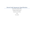
[57]
87011’ 525’ 524; 364/413'02’845'1;
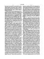
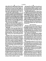
Multiple devices that are each suitable for use at a se
' ’
[56]
' ’
lected one of multiple locations are managed using a
References Cited
U S PATENT DOCUMENTS
4,051,522
network of links that are each assigned to one of the
locations. Each link is selectable between a state in
' '
9/1977 Healeay et a1. ................... .. 340/717
xcGmh et a" '
"
'''
'‘ ' "
4’356’475 10/1982
4:674:085
6/1987 Arangure et al: I ' ' I
4,887,260
12/1989
Carden et al.
ABSTRACT
which a device is not using the link and a state in which
one or mom devices are using the link Links that are in
use by the devices are identi?ed and the locations at
340/525
which the devices are used are determined based on the
' ' ' . ' "370/852
. .. .
. . . . ..
identities Of the links that. are in “Se
340/525
4,916,444 5/1990 King ............................. .. BAD/825.49
40a
41
52 Claims, 13 Drawing Sheets
BEDSIDENETWORK 10d 13/1212‘
r _____________________ “1
MULTIPORTREPEATER / _/’
40b
HEPEATER
BRIDGE/ROUTER
,_.,
CPU
1
15/ I
;
PATIENTCAFIE DEVICE (PCD) 1
UNTERMINATEDLINKS
new
TO EACH BEDSIDE
: {eoY
ONFLOOH
12
;
70
[
.
NETWORK
14
Ir
l
SUPERVISOR 13
FUNCTION
I
I
Q}
1
________ _1§_2Q_- -NLIB§E'§§TATPN26
“a
|
1’)
g
:
WORKSTATION
|
5
24
;
2W WORKSTATION
{
24
;
:
1
I
=
:
\
'
-
‘
3 a
-/
-
;
-
T0 PATIENT
‘ ' ' ‘ ' ' ' ' ' ' ‘ ‘ "E ' ' ' ' ' ' "
WIRELESS
NETWORK
CPU
;
PATIENT
ROOM 15
4
420
-w°°~
4033 ,
‘P j
‘
-
a. my “@551
W9
/V
, ;
4069-1 m5 401
l
1+9}
3o 31
E5113
l
INVASIVE B'P' PULSE ;
B.P.
OXIMETRY:
FEE
'
'
;
g
Lil-3Z1 55-233 ----------- "219-":
I
I
I
t
I
n
.
NONINVASIVE
4,
3
:
t
;
;
;
I / CPU
l
\16;
I
*1
l
I
ECG
‘5
@EL @5192" =
:
NSF ~17
-_2
\ 2 (NSF)
‘7
XCVH
:
_)
‘ W
. i
war-l
402/
40525
o
30
0
HALLWAYALAHM
—2?’——_’ ANNUNCIATOR
‘"‘UXCVH“a
410
_ CELLULAR
17
‘\iBTil
CELLULAR
PCD (ON
AMBULATING
PATiENT)
US. Patent
June 7, 1994
Sheet 7 of 13
/ 102A
C1
/--122 (blue)
0120
FIG7A
/ 102C
/—13O (green)
FIG 7C
/
102a
A136
\138
FIG 7E
?\
/124(yellow)
US. Patent
June 7, 1994
Sheet 8 of 13
5,319,363
r140
1101A
John Smith
ALARM MANAGER
142/,
142/ -NIBP
.9 > (D
150 014sW250
?argsgylou
OFF]
1
147
\.148
mo
142_\TEMP 98.6
@0
100 ~Param 890W OFF|
U-_U 10o \Param Swim OFFI
D_EI 10o \Param SeUIErT OFF]
D———(_{1 10o \Param Swim E]
SYS
12o
0
143/-DIAS
so
0 B————u 1oo\Param SeOfB'N' QEEI
MEAN 100
o D——_U 1oo\Param SeOI'oW OF_F|
142"\INVP2
SYS
DIAS
120
so
MEAN 100
142"‘SAO2
o D—_U 1oo\Pararn Swim O_FF_|
0 U—_—U 1oo\Param sevl'm git-j
I 100 \Param SeUION
OFF
98.6 0 U-—_U 100\ParamSet)|ON OFF]
144
\ Done
\CanceU
149
FIG 8
\Stat Set)
v
US. Patent
June 7, 1994
Sheet 9 0f 13
5,319,363
160\\
1101A
‘
John Smith
i
‘ ""
\190
162
"" "
H
on W
‘i1 110
192
9
AFB
122
Q
I
5
58
Sa°2
92
192
123
so
18:34
84
T1=101.4°F
‘92
CUFF
55351:,
196
M
PATIENT
DISPLAY ,
m
196
DONE
1
194
\111
\yna
FIG 9
1,1
/
(115
US. Patent
LINK 12
608
f )n
2
June 7, 1994
2407
'
242§
I
I
‘1
IN
XCVR
'
7° /
u
l
I
':
a
|
|
|
|
FIG 10
5,319,363
|-
)
v '0‘ Q
Sh4eet 10 of 13 '
LINK
TESTER ~5
'
232
US. Patent
June 7,1994
Sheet 11 of 13
5,319,363
PCD
FIG 12
FIG 11
REPEATER14
E LINKS 12
9—
PRIMARY PCD 16)
——RZ—T—>
Jw~
70
XCVR
RS232
SECONDARY
PCDs
16'
FIG 13
US. Patent
June 7, 1994
Sheet 13 of 13
5,319,363
PCD
50
TO PORT13
OF MULTIPORT
REPEATER 14
60a
/
A
5o
FIG 15
/16
‘
: H
3\
501)\5o3
1
5,319,363
2
Ambulation is possible in stepdown units, which gen
NETWORK FOR PORTABLE PATIENT
MONITORING DEVICES
erally monitor, by RF medical telemetry, exclusively
patients’ electrocardiogram (ECG). ECG RF transmit
This is a continuation of application Ser. No.
07/576,700, ?led Aug. 31, 1990, now abandoned.
connected to a central nurses’ station for observation.
ters worn by the patients transmit ECG data to antennas
The telemetry antenna is permanently mounted near the
patients’ rooms and hard-wired to the nurses’ station.
BACKGROUND OF THE INVENTION
SUMMARY OF THE INVENTION
This invention relates to interconnecting multiple
A general aspect of the invention is managing multi
patient care devices to a central location (such as a
nurses’ station) for observation and control.
A wide variety of patient care devices (PCDs) are
ple devices that are each suitable for use at a selected
one of multiple locations using a network of links that
are each assignedto one of the locations; each link is
currently available. Examples include vital signs moni
selectable between a state in which a device is not using
' tors (which measure such parameters as ECG, non
invasive‘ and invasive blood pressure, pulse oximetry,
etc.), ventilators, and infusion pumps. PCDs typically
the link and a state in which one or more devices are
using the link. Links that are in use by the devices are
identi?ed and the locations at which the devices are
used are determined based on the identities of the links
are not permanently installed beside each bed in every
hospital room in the general care areas of the hospital.
One reason is, of course, the expense of such an arrange
that are in use.
ment, but another, equally practical reason is that pa 20
tients who are cared for in these areas generally do not
require routine use of PCDs.
Often, vital signs monitoring and use of infusion
patients.
pumps are necessary temporarily, for example, for a few
hours after the patient returns to the room from sur 25
gery. This is typically accomplished with portable
PCDs brought to the patient’s bedside. Thus, portable
The invention is advantageously employed to man
age the use and operation of portable patient care de
vices (PCDs) and track the locations of the PCDs as
they are used at various bedsides and by ambulating
Preferred embodiments include the following fea
tures.
‘
The devices send and receive messages to other de
PCDs are used in general care areas on an ad hoc basis
vices on the network via the links. Each link is associ
and it is common for a given PCD to be used in several
ated with a port of a multiport repeater (or terminal
rooms'over the course of a few days. It therefore is 30 server), and the locations of the devices are determined
difficult for a health care provider to determine the
locations of the PCDs and of the patients who are using
them, other than by physically looking in every room
based on the identities of the ports that are associated
with links on which the messages appear. The messages
sent by a particular device identify that device (e.g., by
on the floor. Moreover, it is often helpful to a patient’s
device type) so that a device’s location is correlated
recovery process to allow the patient to ambulate dur 35 with its identity (e.g., as a vital signs monitor, an infu
ing the period that he or she is connected to the PCD;
sion pump, a ventilator, etc.).
locating such a‘ patient is usually done visually by
searching the hallways.
Some of the links comprise unterminated cable (such
as coaxial or twisted pair wiring) ends of which are
General care patients that are using the PCDs are
disposed at different locations. These links are consid
typically the most acute (i.e., medically unstable) pa 40 ered unused unless and until they are terminated, at
tients on the floor (i.e., the patients that bear the closest
which time they are designated as being in use.
monitoring by the ?oor’s staff of health care providers).
Termination may be established in many different
concomitantly, the presence of a PCD at a bedside
ways. One simple technique is to manually connect a
serves as a flag to indicate that the patient should be
terminator to the cable at the time that the device is
monitored carefully. But because the PCDs are located 45 connected to the network. But preferably, the devices
inside of the room, they often cannot be seen from the
each include circuitry that, when the device is con
nurses’ station, and alarms generated by the PCDs (for
example, warning that the patient’s cardiac functions
nected to the network, determines (such as by impe
dance testing) whether the cable is already terminated
have fallen outside of preset limits) may not be easily
by another device, and circuitry for terminating the
detected. Consequently, the patient sometimes is moved 50 cable if it has not already been terminated. If the cable
to another room that is closer to the nurses’ station to
is already terminated (e.g., by a device that had previ
reduce the possibility that alarms may go undetected.
ously been connected to the cable) but the termination
An alternative is to move the patient to a specialized,
is improper for the newly-added device, an impedance
advanced care unit, such as an intensive care unit (ICU)
imbalance is placed on said cable; this causes the previ
or “stepdown” unit for the short time that vital signs 55 ously-connected device to remove the termination,
monitoring is needed. In the ICU, special purpose de
thereby permitting the newly-added device to terminate
vices dedicated to, e.g., ECG monitoring, are perma
nently mounted in each patient’s cubicle. The devices
are connected via a private network (i.e., a network
having a communication protocol not available for
general purpose use) to special purpose displays located
at the nurses’ station so that all of the devices can be
observed centrally. The displays typically can only
display limited information (e.g., heart waveforms and
the cable.
Other links are cellular in nature and adapted to com
‘ municate over a wireless transmission medium with
cellular devices disposed in a predetermined area. Mul
tiple transceivers are arranged on the link and each
transceiver communicates with a device located in a
regional cell within the area that is assigned to the trans
ceiver. Each cellular device transmits messages that
heart rate) and are thus unsuitable for general purpose 65 identify the device, and each transceiver relays mes
use. Moreover, the patients generally cannot ambulate
sages received from a device located in the transceiver’s
throughout the unit while connected to the monitoring
cell and identi?es itself as part of the relaying process.
devices.
The cellular location of a device is determined based at
3
5,319,363
least in part on the identity of the transceiver with
which the device is communicating.
The identity of each device connected to the network
at each location is tracked based on the messages that
the devices transmit. A database for stores information 5
4
reduces the cost of the system and ensures compatibility
with existing and emerging communications devices.
The PCDs areconnected to and disconnected from
the network without disrupting the operation of the
network or the performance of other PCDs, a must in
that designates, for each device, the category thereof
view of the ever-changing locations in which the PCDs
(e.g., whether it is a vital signs monitor, an infusion
are used.
pump, or a ventilator).
The system also includes a processor (such as a work
Besides the numerous benefits to the quality of patient
care, the invention also allows many administration
station) located remotely from the locations of the de
vices (e.g., at a nurses’ station) for communicating with
the devices via the network links.‘ The processor dis
functions involving the PCDs (e.g., inventory control,
plays to a user information about the devices based on
service calls, billing for PCD use) to be automated.
Other features and advantages will become apparent
from the following description, and from the claims.
data received from the devices over the network. The
display enables the user to visualize at a glance the
locations of all devices that are in use on the network
and the status of these devices. Several display formats
DESCRIPTION OF THE PREFERRED
EMBODIMENTS
We ?rst brie?y describe the drawings.
are available to allow the user to view, for example, a
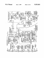
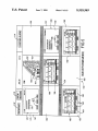
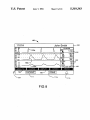
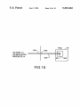
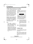
FIG. I is a block diagram that shows a network for
hospital floor at various levels of detail.
portable patient care devices according to the inven
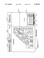
For example, one format displays a floor map to the 20 tion.
user; icons on the map indicate the locations of the
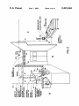
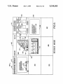
FIG. 2 is a partial, perspective diagram of an area of
devices currently in use on the network. The appear
a hospital floor on which the network has been in
ance of each icon (e.g., its color) designates the status of
stalled.
the corresponding device v(such as whether it is func
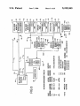
FIG. 3 is a block diagram and table useful in under
25 standing the operation of the invention.
tioning normally or is in an alarm condition).
Another display format allows the user to visualize
FIGS. 4-6 are examples of numerous displays gener
virtual images of the front panels of numerous (e.g., up
ated during the operation of the network.
to eight) devices. This is an invaluable tool that permits
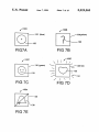
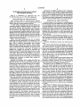
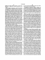
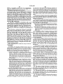
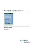
FIGS. 7A-7Eshow several of the icons used in the
the user to monitor the operation of the device from the
displays of FIGS. 4-6.
workstation without having to travel to the physical
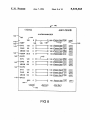
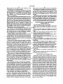
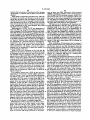
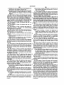
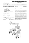
FIG. 8 is an example of a working window used in
location of the device.
the displays of FIGS. 4-6 that enables the user to enter
In yet another format, the area around a particular
information.
location (e.g., a patient’s bedside) is displayed to enable
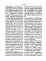
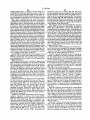
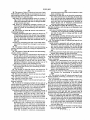
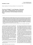
FIG. 9 shows an image of a front panel of a patient
the user to rapidly identify the number and types of
care device included in the displays of FIGS. 4-6.
devices in use at that location, as well as the status of 35
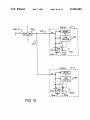
FIG. 10 illustrates terminating the network links ac
each device. If desired, the user can also monitor the
cording to one embodiment of the invention, and FIGS.
virtual images of the front panels of the devices.
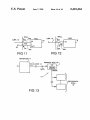
11 and 12 show alternative termination techniques.
A sophisticated user interface allows the user (i.e., a
FIG. 13 shows using the network with patient care
health care provider) to control the operation of any
devices that do not independently send messages over
device on the network. For example, alarm limits may
be set or modi?ed and alarm conditions may be disabled
from the workstation without requiring the user to
travel to the device. Devices are selected for control
the network.
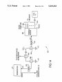
FIG. 14 shows an alternative embodiment of the
network.
FIG. 15 shows a‘ patient care device connected to a
using any one of the display formats described above.
twisted pair link of the network.
The system also includes multiple alarm annunciators 45
disposed at various locations (e.g., throughout a hospi
tal floor) for displaying messages that identify devices
that enter an alarm condition and sounding alarm tones
to warn health care providers of the existence of the
alarm. The annunciators are also controlled (e.g., to
silence the alarm tone) from the workstation via the
user interface.
The invention provides a powerful but straightfor
STRUCTURE AND OPERATION
Referring to FIGS. 1 and 2, bedside network 10 in
cludes links 12 that originate from respective ports 13 of
a multiport repeater 14 and are wired to the vicinity of
every bed (i.e., the bedside) in every patient room 15 on
a ?oor of a hospital. Each floor in, for example, the
general care areas of the hospital includes a bedside
network 10. (Network 10 may extend over more than '
ward and inexpensive solution to the problem of cen
one floor if the floor includes a small number of beds;
trally managing the use and control of portable patient
alternatively, large floors may require more than one
network 10.) As described in detail below, because
general care patients normally are not using patient care
devices, links 12 each are normally unused (i.e., inac
tive). Each link 12 becomes active only when a patient
60 care device (PCB) 16, 16a, such as an vital signs moni
care devices (PCDs). The PCDs are networked without
the need to install a PCD at every bedside, enabling a
hospital to stock relatively few PCDs for a large num
ber of beds. Because all general care bedsides are avail
able for connection to the network, there is no need to
move the patient to the PCD for close monitoring. As a
tor (shown in FIG. 1), a ventilator, or an infusion pump
is put into use on the link 12 in one of the ways de
scribed below. Links 12 that are wired into rooms 15 are
numerous vital functions and other patient care activi
unterminated when not in use. When a PCD 16 is used
ties (e.g., ventilation). Patients are located easily 65 in a room 15, it is connected to a link 12 in such a way
through the utilization and implementation of standard,
as to terminate 18 the link. PCDs 16 are portable so that
result, continuity of nursing care is maintained.
The invention also provides central monitoring of
readily available network hardware and software and
standard network management techniques. This further
they can be brought directly to the bedsides of any
patient in need of them.
5
5,319,363
Multiport repeater 14 is an Ethemet/IEEE 802.3
repeater with uniquely addressable ports 13, such as an
MMAC IRM (Intelligent Repeater Module) from Ca
bletron of Rochester, NH. The operation of repeater 14
is managed by a repeater CPU (central processing unit)
15 which implements network supervisory functions
(NSF) 17, including, for example, simple network man
agement protocol (SNMP) capabilities; other suitable
6
(besides displaying an indication of the alarm on display
24f as described in detail below) sends an alarm message
to annunciators-30. The CPU 31 in each annunciator 30
responds to the alarm message by causing a tone genera
tor 33a to sound an alarm and causing display 33b (a
rectangular array of LEDs) to illuminate a message 35
(FIG. 2) that identi?es the bed at which the alarming
PCD is located and the type of alarm. For example, if
network management protocols may be used instead.
One port 13 of multiport repeater 14 is connected via a
the heart rate of the patient in bed B of room 1124 falls
cable 20 to a workstation 24 (i.e., a data processing
device) located at a nurses’ station 26 on the floor.
Links 12 and cable 20 are l0-base-2 coaxial cable, but
any suitable type of interconnection medium may be
message “RM 1124B LIMIT ECG”. CPUs 31 prioritize
alarm messages from workstation 24 by their type so
that messages 35 for simultaneously existing alarms are
displayed in order of their seriousness or their occur
used instead. For example, links 12 and cable 20 can be
rence.
twisted-pair (IO-base-T) or ?bre optic wiring (FDDI).
outside of preset limits, annunciators 30 display the
As a result, a health care provider can listen and
Another repeater port 13 ‘is connected via cable 19
watch for alarms from annunciators 30 while perform
(e.g., a l0-base-2 coaxial cable) to RF wireless network
ing tasks that take him or her away from nurses’ station
CPU 400. CPU 400 also implements network supervi
26. Annunciators 30 are placed strategically throughout
sory functions (NSF) 17 and drives a wireless subnet 20 the floor (e.g., on the wall above doorways, suspended
work 420 via cable 403, which provides a bus to which
from the ceiling at hallway intersections) so that a
numerous wireless, cellular network transceivers 401
health care provider can observe (and hear) at least one
are connected (only two such transceivers, 401a and
annunciator from nearly any location on the ?oor.
4015, are shown). Cellular transceivers 401 each imple
Bedside network 10 is a local area network (LAN)
ment NSF 17 and are, e. g., mounted at various locations 25 that conforms to Ethernet and IEEE Standard 802.3
in common areas of the floor (such as hallways and
and forms part of a wide area network (WAN) 32 in the
waiting rooms). The operation of wireless subnetwork
420 is discussed in detail below. Suf?ce it here to say
that subnetwork 420 provides virtual links 12’ between
hospital. WAN 32 includes other bedside networks 10
and other types of networks 34, for example, a hospital
wide information network that allow patient data stored
repeater 14 and one or more cellular PCDs 16a in use by 30 in a shared database 36 to be accessed throughout the
ambulating patients (e.g., who are walking in the hall
ways 15a (FIG. 2) of the floor).
hospital. All of the networks 10, 34 are connected via
standard taps 42 to a common link 40 (called a “spine”)
At present, workstation 24 does not include a net
that runs throughout the hospital. Spine 40 is a 10-base-5
work transceiver (i.e., a media access unit or MAU) so
coaxial cable, but any other suitable transmission me
cable 20 is connected via a separate transceiver 21 to the 35 dium can alternatively be used. Each end of spine 40 is
AUI (access unit interface) port of workstation 24.
terminated 41 (by connecting a 50 ohm impedance de
Workstation 24 is a computer (e.g., a Sun Microsystems
vice between the center conductor 40a and the shield
SPARC) with a multitasking operating system 240
40b of spine 40) to minimize signal reflections and pro
(such as Unix) that allows central processing unit (CPU)
vide a suitable transmission medium for messages sent
24b to implement network supervisory functions 17 to 40 over spine 40.
support bedside network 10, while also allowing work
A bridge/router 44 is connected between tap 42 and
station 24 to be used to run other applications programs
multiport repeater 14 in bedside network 10 to control
24d to perform other tasks (such as compiling and re
the transmission of messages between network 10 and
porting acuity levels, ordering laboratory tests, and
other networks via spine 40. Like the other Ethernet
viewing radiology reports, to name but a few). Work 45 devices on network 10', bridge/router 44 implements
station 24 also includes numerous user interfaces 24e
network supervisory functions 17.
FIG. 2 shows the physical arrangement of a portion
(described below) and a high resolution, display 24f to
facilitate ‘the health care provider’s use and operation of
bedside network 10. Other workstations 24 (not shown)
may be connected to bedside network 10 to facilitate
clinical activities.
It will be appreciated that often a single nurses.’ sta
tion 26 serves several rooms 15 (which each include one
of bedside network 10 on a hospital floor. Multiport
repeater 14 and bridge/router 44 are mounted in an
equipment closet 50 for connection to spine 40. Most of
the links 12 are wired on a point-to-point basis to indi
vidual bedsides in rooms 15. Rooms with multiple beds
receive one link 12 for each bed (a private room 15 is
shown in FIG. 2). The end of each link 12 is made
or more patient beds), and that 'PCDs 16 located in
various rooms 15 (or PCDs 160 located in the hallways 55 available for connection to a PCD 16 via a modular wall
of the ?oor) typically cannot be seen or alarms gener
jack 60 located near the patient’s bed 62.
ated by the PCDs heard at the nurses’ station. But as
As discussed, cable 19 is connected to wireless net
described in detail below, bedside network 10 allows
work CPU 400, which is in turn connected by subnet
the health care provider to both monitor the status of
work link 403 to multiple wireless transceivers 401.
and control the operation of any PCD 16, 160 on net 60 FIG. 2 shows one of the transceivers 401a mounted in
work 10 via workstation 24.
the ceiling of the hallway near nurses’ station 26.
Bedside network 10 also includes multiple alarm an
Display screen 24f of workstation 24 enables the user
nunciators 30 connected to the RS232 ports of worksta
(i.e., the health care provider) to visualize at a glance
tion 24 and mounted remotely from the nurses’ station
the locations of all bedsides at which PCDs 16 have
26, such as at selected hallway locations throughout the 65 been connected on network 10 and all cellular PCDs
?oor. As described in detail below, when workstation
160 being used by ambulating patients via conspicuous,
24 receives a message from a PCD 16, 160 that indicates
readily identi?able icons. As discussed below with ref
that the PCD is in an alarm condition, workstation 24
erence to FIGS. 4-6 (which show two types of displays
7
5,319,363
and several icons generated on screen 24]), the icons
also indicate the status of all such PCDs 16, 16a (e.g.,
whether a patient’s vital signs are within or outside of
limits), thereby enabling the user to rapidly locate every
patient being monitored by a PCD 16, 16a on network
10 and determining the patient’s condition simply by
glancing at screen 24f
Network 10 and workstation 24 also enable the user
wired into a patient’s room 15, this determination is
made by detecting whether the link 12 is terminated 18.
Links 12 that are unterminated (e.g., link 12 connected
to port address 131) are determined to be “inactive" or
idle. A link 12 wired to a room 15 remains inactive
unless and until a PCD 16 is connected to the link’s wall
jack 60 in such a way as to provide termination 18 for
to control the operation of every PCD 16, 16a in use on
the link. For the sake of clarity, terminations 18 are
shown schematically in FIGS. 1 and 3; several alterna
bedside network 10 remotely from workstation 24,
tive physical arrangements for providing the termina
without the need for the user to travel to the patient’s
tions are discussed below. Repeater 14 detects that the
bedside. This capability is facilitated by making screen
termination has been made and then designates the link
24] an interactive device (i.e., a touchscreen). Other
as "active”. This is an often used network management
interface devices 24c such as a keyboard 54, "mouse”
technique to identify and shut down normally-ter
minated links that, because of a fault, become unter
minated.
That is, in a typical network, the links are always
terminated, and devices are connected to and discon
nected from a link via taps that do not disturb the termi
to workstation 24 over network 10 is stored in disk 20 nated condition of the link, much like the way in which
bridge/router 44 is connected to spine 40. The inven
drive memory 58 or sent to database 36 for storage. The
56, and tablet 57 provide a comprehensive, easy to oper
ate user interface for control of PCDs 16, 16a and for
data entry. Additional data entry devices (e.g., track
balls, magnetic card readers, and bar code readers, not
shown) may be used as well. Data sent by PCDs 16, 16a
data can also be stored on other media, such as an opti
cal disk or magnetic tape.
Referring also to FIG. 3, each port 13 of multiport
repeater 14 is assigned a unique address 131-13,“.
Ports 13 with addresses 131-13,, (e.g., 36 ports) are con
nected by links 12 to bedsides 62, port address 13(,,+ 1) is
assigned to wireless network CPU 400, and port address
13(,,+2) is assigned to workstation 24. Consequently,
port addresses 131-13,| uniquely identify every bed 62
serviced by network 10, while port address 13(,,.,.])
designates the wireless subnetwork and port address
130,“) identi?es workstation 24. (Alternatively, one or
more port addresses 131-13,, may be connected by a link
tion takes advantage of the existing network manage
ment capabilities to identify an unterminated link (e.g.,
link 12]) using the unique address of the repeater port
(e.g., port 131) to which the link is connected, and
thereby determine which bedsides have not been con
nected to a PCD 16 (and hence, by exclusion, which
bedsides are so connected). This capability is particu
larly important because the topology of network 10—
that is, the status and identities of the ports 13 that are
terminated with PCDs 16-—changes constantly as the
portable PCDs 16 are brought to the bedsides where
they are needed.
A wireless cellular transceiver 402 in each transceiver
401 transmits RF signals 405 and receives RF signals
411 via antenna 406 from a small, localized “cell" (e.g.,
having a lOO foot radius) to provide a wireless virtual
link 12' to any cellular PCD 160 that comes within its
During operation of multiport repeater 14, repeater
cell (as would occur, for example, when an ambulating
CPU 15 and NSF 17 monitor ports 13 to determine
whether each is in use. This information is available to 40 patient wearing a cellular PCD 16a enters the cell).
Cellular PCDs 160 (only one of which is shown in
workstation 24. As shown schematically in FIG. 1, the
FIGS. 1 and 3) each implement NSF 17 and include a
repeater ports 13 connected to workstation 24 and wire-_
cellular transceiver 410 that transmits RF signals 411
less network CPU 400 are always terminated 18.
and receives signals 405 via antenna 412. Signals 411
Every PCD 16 that is constructed to operate over an
12 to a room in which PCDs are stored when not in use;
connection of the PCDs to such link in the storage room
allows the PCDs to be inventoried via network 10.)
Ethernet and IEEE 802.3 network includes a trans 45 include, among other information, the unique address
ceiver 70 that is programmed upon manufacture with a
unique network (i.e., Ethernet) address 72. Likewise,
wireless network CPU 400 is programmed with a
unique network address 73, cellular transceivers 401 are
each programmed with a unique network address 75,
and each cellular PCD 16a is programmed with a
unique network address 77. This provides a simple,
straightforward mechanism by which workstation 24
(or database 36) can identify, not only the addresses
131—13(,,.,. 1) of the ports 13 and the cellular transceivers
77 that identi?es the PCD 16a. The cellular transceiver
401 that receives signals 411 adds its network address 75
and forwards the signals to repeater 14 via cable 403,
wireless CPU 400, and cable 20. Thus, workstation 24
can identify the status and approximate location (to an
accuracy de?ned by the area of each cell) of any cellu
lar PCD 160 that is in active communication with a
network transceiver 401 by identifying the network
address 75 of the network transceiver 401 that is cur
rently receiving signals 411 from that PCD 16¢
401 that are that are in use (and hence the locations of
The network control embodied in the workstation
the PCDs 16 and PCDs 160), but also the types (e.g.,
supervisory software 24c and the network supervisory
functions 17 implemented in repeater 14 and in each
PCD 16, 16a manages the information regarding the
vital signs monitors, ventilators, and infusion pumps)
and serial numbers of PCDs 16, 160 that are using net
work 10. One bene?t of this capability is central, hospi 60 presence or absence of every device in use on network
10, the data path (i.e. hard wired link 12 or virtual link
trative functions concerning the PCDs (e.g., inventory
12’) being used by each device, and the operational
characteristics of each such device. The basic function
control, service calls, and billing for PCD use).
tal-wide WAN automated control of numerous adminis
of multiport repeater 14 is to repackage messages re
In operation, one of the network management tasks of
workstation 24 takes advantage of the ability of multi 65 ceived at an active port address 131-130,“) and glob
ally resend them from every other active port address
port repeater 14 to determine whether each port 13 is
connected to a link 12 that is active (i.e., in use by a
131—13(,,+2) for receipt by a device (e.g., a PCD 16, 160
or workstation 24) linked thereto by the network. In
PCD) or inactive (i.e., unused). For each link 12 that is
5,319,363
9
10
addition, the unique address 131-13(,,+2) of each port
an access code that enables them to obtain such cardiac
identi?es the origination of packets transmitted on its
data, but only for their own patients.
link 12.
Workstation 24 generates numerous displays on
screen 24f that allow the user to visualize at a glance the
'
.
Each message is arranged as a packet that includes
the source address of the message (e.g., the unique net
work address 72 of a PCD 16 or the unique address 77
of a PCD 16a), the destination address of the message
(e.g., the network address of workstation 24), and data.
In addition, repeater 14 inserts into the packet a speci?c
identi?cation stamp that identi?es the address of the
port 13 which received the packet from link 12. Other
devices (such as other PCDs 16, 160) that receive the
message after it is retransmitted by repeater 14 simply
ignore it unless'their network addresses match the mes
locations of the bedsides that are equipped with PCDs
16, the locations of cellular PCDs 160 on the floor, and
the status of the PCDs 16, 160 being used (e. g., whether
the PCDs are in an alarm condition). The user also
interacts with PCDs 16, 16a from the workstation (e.g.,
to control their operation and to change alarm limits,
etc.)
Referring to FIGS. 4-6, the user may select several
different such displays, only three of which are shown
in the ?gures. In the “map” display mode 100 shown in
FIG. 4, a floor plan 101 is displayed which shows each
sage’s destination address. Thus, messages sent by a
room 15 on the floor as well as the hallways 15a and
PCD 16, 16a to workstation 24 are accepted by work
other common areas on the ?oor. Floor plan 101 also
,’station 24 and ignored by the other PCDs on the net
includes one or more icons 102 in each room and in the
work, and messages sent by workstation 24 to a given
hallways and common areas to designate the bed or
PCD 16, 16a are accepted by that PCD only. Database
36 (or workstation memory 58) stores, among other 20 beds in the room, indicate the beds that are equipped
with PCDs 16 connected to network 10, and show the
information, records that associate each network ad
approximate
locations of active cellular PCDs 16a. The
dress 72, 75, 77 with a PCD type (e.g., vital signs moni
“waveform” display mode 150 shown in FIG. 5 permits
tor, ventilator, infusion pump, etc.) and serial number,
the user to visualize in real time up to eight virtual
thereby enabling workstation 24 to identify the type of
PCD from which an incoming message originated sim 25 images of front panels of PCDs 16, 16a being used on
network 10. A third, “bedside” display mode (shown in
ply by inspecting the database records.
FIG. 6) shows the user a virtual image of a selected
Workstation 24 constructs a management table 80 by
bedside and displays icons that identify one or more
which it keeps track of the active/inactive status of all
PCDs 16 connected to network 10 at the bedside and
of the ports 13 and their corresponding locations on the
indicate the status of each PCD. Up to seven virtual
network, the network address of each PCD connected
images of PCD front panels can also be displayed for
to an active port, and the identity of each such PCD.
Thus, a user at workstation 24 can easily determine the
locations of the bedsides at which PCDs 16 are in use,
that patient.
Referring to the map display mode 100 in detail,
display 100 also includes a workspace 104 that enables
the cells in which wireless PCDs 160 are being used, 35 the user to display a virtual image 106 of the front panel
and the identity of each type of monitor being used at
of a PCD 16, 160 (image 106 is of the front panel of a
each such bedside and in each such cell. For example,
vital signs monitor manufactured by Protocol Systems,
the user can quickly determine that the patient in bed
Inc. and is described in detail below). The user chooses
1101A (the bed that corresponds to port address 13b) is
which PCD virtual image 106 to display by selecting
using a vital signs monitor, while the patient in bed
the icon 102 that represents the location of the bedside
1119A (port address 13n) is using a vital signs monitor,
PCD 16, 16a of interest. This is done by moving pointer
an infusion pump, and a ventilator. By accessing admit
ting or patient census records (via hospitalwide infor
mation network 34), or by entering patient identi?ca
108 to the icon 102 with mouse 56 and “clicking” the
mouse. Workspace 104 has room for other windows
(not shown) to enable the user to, e.g., enter patient
tion information, the user can link patient names with 45 data, set PCD operating parameters (discussed below),
PCDs 16 at speci?c bed locations. Additionally, table
and perform other tasks without exiting the network
80 shows that wireless subnetwork 420 is active and is
application of workstation 24.
currently communicating with a vital signs monitor 160
A header on display 100 includes buttons 110, 112
located within the cell of transceiver 401b (which is
that enable the user to quickly select the “waveform”
located in “hallway B” of the floor).
50 display mode or the “bedside” display mode by clicking
Moreover, because network 10 (and hence the data in
on the respective buttons using mouse 56. The user is
table 80) is accessible via WAN 32 from other comput
also permitted to suspend the alarm tone generated by
ers in the hospital, the utilization of PCDs 16, 160 can be
annunciators 30 (but not the message displayed by the
observed and managed on a hospital-wide basis. Among
annunciators) by clicking on the “suspend alarm” but
other advantages, this provides ef?cient allocation of 55 ton 114. (This technique can also be used to silence the
hospital resources. It also enables rapid determination
local alarms produced by the PCDs.) When the alarm
of the locations of all patients in a particular classi?ca
tone is disabled in this way, the label of button 114
tion (e.g., all patients that are connected to vital signs
changes to “resume alarm” to indicate that action is
monitors). Security codes can be employed to prevent
required from the user to permit the alarm tone to again
unauthorized inquirers from obtaining sensitive infor 60 be generated. After a time-out period with no action
mation about the patients to ensure patient privacy. For
from the user, the alarm tone is reenabled and the label
example, the cardiac department may be given an ac
of button 114 changes back to “suspend alarm.” The
cess code that enables them to determine (via an inquiry
header also includes an area 109 that duplicates the
made on the hospital-wide information network 34) the
current message being displayed by alarm annunciators
locations of all patients whose electrocardiogram activ 65 30. In the absence of an alarm, annunciators 30 display
ity is being monitored with a vital signs monitor PCD,
the date and time, as shown in FIG. 4; when an alarm
but prevents them from obtaining the cardiac data gen
tone is suspended as described above, the message dis
erated by the PCDs; admitting physicians may be given
played by the annunciators (and duplicated in area 109
5,319,363
11
includes the bed number of the alarm and the message
“SYS SUSP" to indicate that the alarm tone has been
disabled.
Other means of suspending the alarm tone, which do
not require the health care provider to be at the work
station may be used as well. For example, a set of physi
cal keys or buttons may be arranged at numerous loca
tions throughout the floor, or the health care provider
12
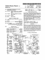
such as heart rate (HR), noninvasive blood pressure
(N IBP), temperature (TEMP), invasive blood pressures
(INVPl and INVP2), and pulse oximetry (SA02). For
each function 142, one or more parameters 143 are also
listed next to the current reading 144 for each parame
ter. The image of a sliding bar 145 with a knob 146 is
provided for each parameter that enables the user to set
the upper and lower limits for each parameter.
may carry an infrared emitter. These devices are linked
The limits are set by clicking on the "parameter set"
to the workstation so that, when actuated, they cause 10 button 147 adjacent to the bar. This causes the corre
the alarm tone to be disabled.
.
sponding image of an "on” button 148 to appear de
Referring also to FIGS. 7A-7E, the appearance of
pressed and the alarm limits to be automatically set
each icon 102 (e.g., its color) is a function of the pres
around the current physiological condition of the pa
ence or absence of a PCD at the bed that the icon repre
sents and the status of the PCD (e.g., whether the iden
tient. The limits are changed by clicking on the knob
146 and sliding it to the left or right; releasing the button
tity of the patient who is using the PCD has been con
on the mouse sets the limit corresponding to the posi
?rmed, whether the user has set the PCD’s alarm limits
tion of the knob 146. Additional alarm parameters may
and whether the PCD is operating within the limits or is
be set or modi?ed as necessary in the same manner.
in an alarm condition). FIG. 7A shows an icon 1020 for
When all alarm limits have been set as desired, the user
an “inactive” bedside, that is, a bed at which a PCD is 20 returns to the active map display 100 by clicking on
not connected to a network link 12 (or, alternatively,
“done” button 149.
connected to link 12 but not turned on). Icon 1020 in
When workstation 24 determines that the patient‘s
cludes a connector 120 within a blue colored square
identity has been entered, the operational limits of PCD
122. (Alternatively, the display of icons for inactive
16, 160 have been set, and that information from the
bedsides can be suppressed to reduce the number of 25 PCD is being correctly received over the network and
icons presented to the user.)
.
When a PCD 16 is connected .to the wall jack 60
is within the limits set by the user, it changes yellow
icon 102b to green icon 1020 (FIG. 7C), thereby indicat
ing that all is well at the location of the PCD. Icon 102c
assigned to the bed (and tamed on), the network link 12
is terminated, and the transceiver card 70 in the PCD
consists of a character 128 (such as a smiling face)
has identi?ed itself to workstation 24, icon 102a is re 30 within a green colored square 130.
placed with icon 102b (FIG. 7B). Icon 102b also appears
Occasionally, the information reported by a PCD 16,
when a newly-used cellular PCD 16a is detected by
transceiver 401. Icon l02b includes a yellow square 124
16a to workstation 24 falls outside of the limits set by
(e.g., in place of blue square 122), and a question mark
126 appears inside of square 124. This cues the user that
more information about this connection to network 10 is
needed. For example, the identity of the patient in the
the user or the PCD reports the occurrence of a fault.
This can happen in many ways. For example, the heart
rate detected by a vital signs monitor may become irreg
ular, too low or too high; an infusion pump might ex
haust its fluid reservoir or detect a downstream occlu
sion; or the patient‘s airway pressure as detected by a
bed may need to be entered (if it has not already been
supplied) or con?rmed. In addition, the user needs to
ventilator may fall outside safe limits. When worksta
ensure that the operational “alarm limits” of PCD 16, 40 tion 24 detects such an event, it changes the icon 102
16a have been set.
that corresponds to the patient‘s bed or cellular location
For example, assume that a PCD 16 has just been
of the PCD to alarm icon 102d (FIG. 7D). Alarm icon
connected to network 10 at bedside 1101A (labeled in
102d is a red square 132 that ?ashes 134 (e.g., once per
FIG. 4). The user "clicks” on the icon 102b representing
second) to warn the user of the existence of an alarm.
bed 1101A with pointer 108 and moves the pointer to 45 Red square 132 contains a character 135 (such as a
workspace 104. This causes a virtual image 106 of the
heart) that indicates the type of alarm.
front panel of the PCD (e.g., a vital signs monitor) to
appear. Note that whenever a PCD virtual image 106 is
displayed, a path line 107 is displayed that connects
nurses station 26 with the room in which the PCD 16,
16a is located. This feature enables the user to associate
image 106 with a real location on the ?oor. The user
enters the necessary patient information by using mouse
56 (FIG. 2) to select the “patient" button 111 on image
In addition, the virtual image 106 of the front panel of
the alarmed PCD 16, 16a is automatically displayed in
workspace 104 (FIG. 4). Thus, the user in nurses’ sta
tion 26 is immediately noti?ed of the alarm condition
(even if the patient is in a remote room on the floor) and
can observe the status of the alarmed PCD and, if neces
sary, control the PCD from his or her position at work
station 24. Workstation 24 also sends a message to hall
106. This causes a window (not shown) to appear in 55 way annunciators 30 (FIG. 1), causing them to sound an
alarm and display a message identifying the bed at
data such as name, room number, and admitting physi
which the alarm is occurring and the type of alarm. The
cian via keyboard 54 or with other devices such as
effect is to convert an alarm generated locally by a PCD
magnetic card or bar code readers (not shown). When
(which emits an alarm tone that may not be heard, e.g.,
all of the information has been entered, the user clicks 60 outside of the immediate vicinity of the patient‘s room)
on an icon in the window to redisplay image 106.
into a global alarm that can be seen and heard practi
Referring also to FIG. 8, the entry of a PCD’s opera
cally anywhere on the ?oor. In noise-sensitive areas of
tional limits (such as its alarm limits) is also menu
the hospital, or at certain times of day (e.g. night) when
driven. The user clicks on the “alarms" button 113
audible annunciation is offensive, other means of draw
(FIG. 4) on the image 106 of the PCD of interest, caus 65 ing attention to the presence of an alarm condition may
ing workstation 24 to display an alarm manager window
be used as well. For example, workstation 24 may be
140 in work area 104. Alarm manager 104 identi?es the
equipped (e.g., with a modem or a transmitting antenna)
types of functions 142 being monitored by the PCD,
to activate a standard alphanumeric display-equipped
front of image 106 with spaces for entry of the patient