1
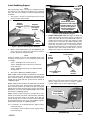
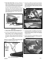
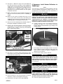
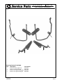
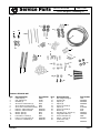
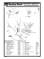
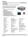
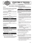
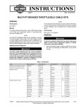
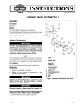
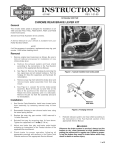
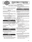
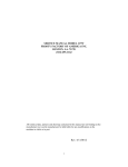
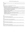
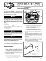
INSTRUCTIONS
®
REV. 11-8-00
-J01924
Kit Number 90126-00
DYNA SADDLEBAG KIT
General
i03111.eps
This saddlebag kit is designed to fit 1996 and later Dyna
Model Motorcycles, except 2000 and 2001 FXDX and 2001
FXDXT.
Terminal
Pick
2-Pin
Connector
See Service Parts Pages for kit contents.
1WARNING
Additional weight can affect motorcycle stability,
handling characteristics and safe operating speed. Do
not exceed 7 lbs (3.2 Kg) maximum load in each
saddlebag. Evenly distribute weight between each
saddlebag. Improper loading may lead to instability
which could result in an accident and death or serious
injury.
Figure 1. Disconnect Turn Signals (2000 Shown)
Installation
NOTE
A Service Manual for your vehicle is available at your
Harley-Davidson Dealer.
1.
Remove seat.
1WARNING
To protect against shock and accidental start-up of
vehicle, disconnect the negative battery cable before
proceeding. Inadequate safety precautions could result
in death or serious injury.
1WARNING
Always disconnect the negative cable first. If the
positive cable should contact ground with the negative
cable installed, the resulting sparks may cause a battery
explosion resulting in death or serious injury.
2.
Disconnect battery cables, negative cable first.
3.
On FXDS-Conv models, follow instructions in Service
Manual and remove existing saddlebags and mounting
hardware.
6.
b.
See Figure 1. Disconnect left and right turn signal
(2-Place) connectors from sockets. Cut wires at
connector as close to terminal end as possible.
Discard connectors and terminals.
c.
Gently pull turn signal wiring out (from tail/stop
lamp assembly, and from clip under rear of fender).
See Figure 2. Remove rear turn signals according to the
following:
FXD, 1999 FXDX, FXDL and FXDWG. Remove signal
lamp assembly by removing bolt inside rear fender.
Remove lamp housing from bracket and pull wiring
through bracket. Repeat for the opposite side. Discard
lamp brackets.
FXDS-CONV. Unscrew the lamp housing from the turn
signal bar and pull wiring through fender and bar.
Repeat for the opposite lamp. Remove nuts under
fender securing turn signal bar. Discard bar.
i03112.eps
Lamp Housing
Bolt inside
Fender
Remove Turn Signals
4.
5.
Refer to the Appendix covering Amp Electrical
Connectors in applicable Service Manual and locate left
and right signal wiring at turn signal connector under
seat. Unplug connector and following instructions in
Service Manual, remove terminals from connector.
On 1996 to 1998 Models, pull turn signal wires through
clips (if present), and fender.
Lamp Bracket
(All except
FXDS-Conv)
Turn Signal Bar
(FXDS-Conv)
On 1999 and later models, perform the following:
a.
Remove two screws securing tail/stop lamp lens
assembly and remove lens assembly.
Figure 2. Rear Turn Signal Mounting Hardware
1 of 7
Install Saddlebag Support
Install Bolts
from inside
fender
i03114.tif
NOTE
When performing Steps 7 through 23 completely perform
procedures for one side before continuing to the opposite
side. This will ensure fender will remain supported during
installation.
7.
See Figure 3. Remove remaining bolt (from inside
fender) securing strut to fender.
NOTE
Install Docking Points
between Strut and Support
If Docking Points are not
present, install Spacers
(P/N 91414-00) between
Strut and Support.
i03113.tif
Remove
remaining
Fender/Strut
Bolt
Hardware
removed with
Turn Signal
Assembly
Figure 4. Install Saddlebag Support
Install
Chrome
Plated Hole
Cover
Figure 3. Remove Remaining Strut Hardware
8.
Obtain chrome plated hole cover (P/N 56239-93) and
press into hole of original turn signal wire entrance
location. Repeat for the opposite side.
NOTE
Before proceeding to the next step, determine which of the
following cases pertains to your installation and install
accordingly.
11. Standard Style Signal Lamp: See Figure 5. Obtain left
signal lamp housing removed previously and left turn
signal relocation bracket (P/N 90139-00). Remove
conduit and cut wiring 12 inches from entrance to lamp
housing. Cut a 1 inch section off conduit and slide it over
wiring up to the entrance of the lamp housing. Moisten
wires with wet paper towel or rag and insert wires
through relocation bracket as shown until wires exit from
opposite end of tube. Slide conduit down to protect
wiring at wire entrance of relocation bracket.
i03115.tif
Wires
Exiting
Bracket
Case 1. Installing kit onto stock motorcycle.
Case 2. Installing kit onto stock motorcycle with nonstock, wide seat.
Case 3. Installing kit onto motorcycle with detachable
docking points.
9.
See Figure 4. Obtain left saddlebag support.
Case 1. Apply Loctite 243 (blue, provided in kit) onto threads
of two bolts (P/N 4164). Install washers (P/N 6701) onto
bolts. From the inside of the fender, place bolt and washer
through hole in fender and strut. Secure bolt into threads of
saddlebag support.
Case 2. Apply Loctite 243 (blue, provided in kit) onto threads
of two bolts (P/N 4164). Install washers (P/N 6701) onto
bolts. From the inside of the fender, place bolt and washer
through hole in fender and strut. Place spacer (P/N 9141400) between strut cover and saddlebag support. Secure bolt
into threads of saddlebag support.
Case 3. Apply Locktite 243 (blue, provided in kit) onto
threads of two bolts (P/N 4218). Install washers (P/N 6701)
onto bolts. From the inside of the fender, place bolt and
washer through hole in fender and strut. Place detachable
docking point between strut cover and saddlebag support.
Secure bolts into threads of saddlebag support.
Signal Relocation
Bracket
1 inch Conduit
Wires
Entering
Bracket
Figure 5. Install Wiring and Conduit into Bracket
See Figure 6. Apply LOCTITE 243 (Blue) to screw (P/N
3538). Using screw and lock washer (P/N 7042), attach
lamp to signal relocation bar as shown. Tighten
securely. Repeat step 11 for the opposite signal.
i03116.tif
Install Rubber
Plug to Opening
10. If installing 3 inch (Standard Style) Signal Lamps,
proceed to step 11.
If installing 2-3/8 inch (Deuce Style) Signal Lamps,
proceed to step 12.
-J01924
Screw and Lock Washer
Figure 6. Installing 3 inch Turn Signals
(Standard Style)
2 of 7
12. Deuce Style Signal Lamps: See Figure 5. Obtain left
signal lamp housing and left turn signal relocation
bracket (P/N 90139-00) Cut wiring 12 inches from
entrance to lamp housing. Moisten wires with wet paper
towel or rag and insert wires through relocation bracket
as shown until wires exit from opposite end of tube.
See Figure 7. Apply LOCTITE 243 (Blue) to screw (P/N
4092). Using screw, lock washer (P/N 7042) and spacer
(P/N 65849-01), attach lamp to signal relocation bar as
shown. Spacer should be installed between signal and
signal relocation bar. Tighten securely. Repeat step 12
for the opposite signal.
15. See Figure 9. Obtain three adhesive backed wire
harness retaining clips (P/N 10102). Remove adhesive
and install clip under fender strut in front of rear shock as
shown in upper portion of Figure 8. Install two remaining
clips under fender strut at locations shown in lower
portion of Figure 8.
i03118.tif
i03353.tif
Retaining Clip
Spacer
i03119.tif
Strut
Lock Washer
Screw
Install Rubber Plug
Retaining Clips
Figure 7. Installing 2-3/8 inch Turn Signals
(Deuce Style)
Figure 9. Install Wire Harness Retaining Clips
13. Install small black rubber plug (P/N 53644-00) to cover
opening of tube on bracket. Repeat for opposite side.
14. See Figure 8. Obtain Wiring Harness and two Sealed
Butt Connectors from kit. Following instructions in
Service Manual under “Installing Sealed Butt
Connectors”, match wire colors and splice wiring from
turn signal to harness. Slide conduit from harness over
Butt Splices and approximately 2 inches into bracket
tube.
NOTE
Cutting one of the wires slightly shorter before installing
connectors will “Stagger” the location of the butt splices and
make sliding conduit over wiring much easier.
16. See Figure 10. Obtain left saddlebag, 3 small grommets
(P/N 90148-00) and 2 large grommets (P/N 11447).
Install the large grommets to the upper two holes and 3
small grommets to lower 3 holes in the saddlebag
assembly as shown.
17. Install two large spacers (P/N 90149-00) into the upper
grommets and three small spacers (P/N 90186-00) into
the lower grommets as shown.
i03120.tif
Larger Grommets and Spacers
i03117.tif
Butt Connectors
Note “Staggered”
Locations
Slide Conduit
from Harness
over Butt
Connectors
after
Installation
Smaller
Grommets
and Spacers
Figure 10. Install Grommets and Spacers
Figure 8. Install Wiring Harness
-J01924
3 of 7
18. See Figure 11. Obtain two large screws (P/N 4098) and
four large flat washers (P/N 6416). Install saddlebag to
support with screw through washer and grommet (in
saddlebag), then through washer (P/N 6416) and into
threaded portion of saddlebag support. Repeat for the
remaining screw and two washers. Do not tighten
completely at this time.
19. Obtain screw P/N 4219, washer P/N 6333 and flange nut
P/N 7531 and secure bottom portion of saddlebag to
support.
20. Obtain left turn signal assembled previously. Insert
screws (P/N 4219) and washers (P/N 6333) into
saddlebag, then into left turn signal bracket and through
saddlebag support. Install flange nuts (P/N 7531).
21. Return to all screws and flange nuts installed in Steps 18
through 20 and tighten all hardware securely.
22. Return to left side wiring harness and route harness
along bottom of strut and insert into retaining clips
installed in Step 15. Adjust, if necessary, then bend clip
tabs to capture wiring in place.
i03121.tif
If Necessary, install Amber Reflectors to
Saddlebags
NOTE
In the next step, red reflectors are pre-installed to meet the
US and Canadian requirements. Amber reflectors are
provided and can be installed to meet the requirements of
markets other than the US or Canada.
1WARNING
Federal Motor Vehicle Safety Standard (FMVSS) 108
requires all motorcycles to be equipped with side
reflectors. Install, or have Dealer install, the reflectors
supplied with this kit. Visibility is a major concern to
motorcyclists. Failure to install all side reflectors could
result in an accident and death or serious injury.
26. If amber reflectors need to be installed, perform the
following: See Figure 13. Locate reflector mounting
location under the Harley-Davidson Logo. Gently pry out
existing reflector.
i03123.tif
Reflector Location
Screws and
Washers
Secure Saddlebag to
Lower Support using
Screw, Washer and
Flange Nut
Install
Washer
between
Saddlebag
and Support
also
Figure 13. Install Reflectors
Screws, Washers for Mounting Turn
Signal Relocation Bracket
Figure 11. Install Saddlebag to Support
23. See Figure 12. Continue routing wiring harness under
front of strut in front of fender and through middle boxed
area of frame to Connector [7].
27. Use isopropyl alcohol to thoroughly clean the area, then
let dry completely. Remove adhesive backing and install
amber reflector. Repeat for opposite saddlebag. Let
adhesive cure for 24 hours.
28. Connect battery cables, positive cable first.
1WARNING
Always connect the positive battery cable first. If the
positive cable should contact ground with the negative
cable installed, the resulting sparks may cause a battery
explosion which could result in death or serious injury.
i03122.tif
29. Install seat.
Turn Signal
Connector [7]
Wiring routed
into boxed
area of frame
Figure 12. Route Wiring to Connector [7]
24. Follow instructions in the Service Manual to install pin
terminals to cavities in Turn Signal Connector [7].
25. Repeat Steps 7 through 24 for the right saddlebag.
-J01924
1WARNING
After installing seat, pull upward on front of seat to be
sure it is locked in position. If seat is loose, it could shift
position during vehicle operation causing loss of control
of vehicle and death or serious injury.
1WARNING
Check for proper turn signal lamp operation before
riding motorcycle. Visibility is a major concern for
motorcyclists. Failure to have proper turn signal lamp
operation could result in death or serious injury.
30. Check turn signals for proper operation.
4 of 7
®
Service Parts
Part No. 90126-00
Date 11/00
Dyna Fiberglass Saddlebag Kit
i03124.tif
1
2
3
4
Mounting Bracket Kit 90150-00
Item
Description
Part Number
1
2
3
4
90136-00
90137-00
90138-00
90139-00
Bracket, mounting right hand
Bracket, mounting left hand
Bracket, turn signal mounting right
Bracket, turn signal mounting left
11
-J01924
5 of 7
®
Part No. 90126-00
Service Parts
Date 11/00
Dyna Fiberglass Saddlebag Kit
i03125a.tif
17
3
15
23
22
1
12
16
9
5
21
14
6
18
13
4
2
19
11
7
10
8
20
25
24
Hardware Kit 90106-00A
Item
Description/Qty
Part Number
Item
Description/Qty
Part Number
1
2.
3
4
5
6
7
8
9
10
11
12
13
Cable strap (4)
Clip, adhesive (6)
Grommet (4)
Screw hex socket button (2)
Screw, button socket head (4)
Screw, hex socket button head (6)
Reflector, amber right hand
Reflector, amber left hand
Washer, plain (6)
Washer, plain (8)
Lockwasher, hi collar (2)
Harness, turn signal wire (2)
Connector, sealed butt (4)
10065
10102
11447
3538
4098
4219
59289-92
59290-92
6333
6416
7042
70550-00
70585-93
14
15
16
17
18
19
20
21
22
23
24
25
26
Nut, flange locking (6)
Grommet (6)
Spacer (4)
Spacer (6)
Screw, hex head (4)
Spacer (4)
Screw, hex head (4)
Washer (4)
Hole plug cover, chrome (2)
Plug, black rubber (2)
Screw, 5/16x18x1 (2)
Spacer, .150 inch (2)
Loctite 243 (.5 ml)
(not shown)
7531
90148-00
90149-00
90186-00
4164
91414-00
4218
6701
56239-93
53644-00
4092
65849-01
-J01924
94635-98
6 of 7
®
Service Parts
Part No. 90126-00
Date 11/00
Dyna Fiberglass Saddlebag Kit
i03126.tif
5, 6
11
27
9
22
29
18
7
13
20
21 17
24
25
30
23
15
12
19
3, 4
14
8
28
16
26
1, 2
10
Saddlebag (Left) P/N 90147-00
Saddlebag (Right) P/N 90141-00
Item
1
2
3
4
5
6
7
8
9
10
11
12
13
14
Description (Qty.)
Saddlebag bottom, right hand
Saddlebag bottom, left hand
Saddlebag lid, right hand
Saddlebag lid, left hand
Reflector, red right hand
Reflector, amber right hand
Reflector, red left hand
Reflector, amber left hand
Plate, cam lock
Keeper, latch
Medallion, H-D
Plate, lid hinge mount
Plate, base hinge mount
Plate, latch backing
Cam, latch lever
Latch assembly
-J01924
Saddlebag Assembly
Part No.
90127-00
90128-00
90129-00
90134-00
59287-92
59289-92
59288-92
59290-92
91393-00
91392-00
90167-00
90158-00
90188-00
90159-00
91390-00
90166-00
Item
15
16
17
18
19
20
21
22
23
24
25
26
27
28
29
30
Description (Qty)
Hinge assembly
Cover, latch
Lever, latch
Lock assembly (1 of 2)
Cam block
Screw, #10-16x1/2 self tap (9)
Washer, non metallic
Nut, keps #10-32 (3)
Screw, M6-6Hx25 (2)
Screw, #8-32
Washer, flat #8
Screw, button head 1/4-20x1/2 (2)
Gasket
Label saddlebag
Plate, hinge cover
Screw, 1/4-20x1/4
Part No.
90151-00
91391-00
91386-00
90168-00A
91389-00
5233
91387-00
7629
1396
4241
6182W
936
90174-00
90248-00
91375-00
1397
7 of 7