1
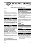
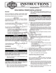
-J02811
REV. 2015-05-27
MULTI-FIT BRAIDED THROTTLE/IDLE CABLE KITS
GENERAL
NOTE
Kit Numbers
This instruction sheet references service manual information.
A service manual for the specific model motorcycle is required
for this installation and is available from a Harley-Davidson
dealer.
See Table 1.
Models
For model and fitment information, see the P&A Retail Catalog
or the Parts and Accessories section of www.harley-davidson.com (English only).
Kit Contents
See Figure 11 and Table 2.
REMOVAL
NOTE
The Multi-Fit Throttle/Idle Cable Kits are available in a variety
of housing lengths, fitting angles, and travel lengths. Shorter
or longer lengths may be necessary when modifications (i.e.
optional handlebars) have been made to the motorcycle. See
the P&A Retail Catalog for fitment and length information.
Additional Parts Required
To prevent accidental vehicle start-up, which could cause
death or serious injury, disconnect negative (-) battery
cable before proceeding. (00048a)
1.
Disconnect battery cables, negative cable first or remove
the main fuse following the instructions in the service
manual.
The rider's safety depends upon the correct installation
of this kit. Use the appropriate service manual procedures.
If the procedure is not within your capabilities or you do
not have the correct tools, have a Harley-Davidson dealer
perform the installation. Improper installation of this kit
could result in death or serious injury. (00333a)
Table 1. Kit Numbers
Model
Sportster®
Sportster®
Stainless Steel Kit
Diamondback Kit
Diamond-Black Kit
Angle Length in. (cm)
models (2006 and earlier)
56564-02
56715-06
N/A
45°
28.5 (72.4)
models (2007 and later)
N/A
56100196
56100197
45°
28.5 (72.4)
N/A
56726-07
38945-09
45°
30.5 (77.5)
56340-04
N/A
N/A
31.5 (80.0)
56360-09
38906-07
38913-09
32.5 (82.5)
56723-04
N/A
N/A
34.5 (87.6)
N/A
N/A
56100019
N/A
56100147
56100139
90°
27.5 (69.9)
56345-03A
56808-05A
38947-09
90°
26.5 (67.3)
55715-07
38781-06
38946-09
28.5 (72.4)
56344-03A
56807-05A
38954-09
30.5 (77.5)
56579-02A
56805-05A
38918-09
32.5 (82.5)
56350-03A
55700-07
38957-09
34.5 (87.6)
56370-03B
55703-07
55748-10
36.5 (92.7)
56371-03B
55706-07
55767-10
38.5 (97.8)
55718-07
55709-07
N/A
40.5 (102.9)
56373-03A
55712-07
N/A
56720-03
N/A
N/A
Sportster® models
Softail® and Dyna® models
-J02811
25.5 (64.8)
42.5 (108.0)
70°
32.5 (82.5)
Many Harley-Davidson® Parts & Accessories are made of plastics and metals which can be recycled.
Please dispose of materials responsibly.
1 of 6
NOTE
is02071
When performing cable disassembly procedures, make careful
notes as to the existing cable routing. Pay special attention to
existing cable strap locations before removing so new straps
can be placed into the same locations.
1
3
Do not remove or install the master cylinder assembly
without first positioning a 5/32-inch (4 mm) thick insert
between the brake lever and lever bracket. Removing or
installing the master cylinder assembly without the insert
in place may result in damage to the rubber boot and
plunger on the front stoplight switch. (00324a)
2.
See Figure 1. Place the cardboard insert between the
brake lever and lever bracket.
3.
See Figure 2. Loosen cable adjuster jam nuts. Turn cable
adjusters in until they are as short as possible. This will
provide enough slack for easy removal.
4.
Remove the right upper and lower switch housing screws.
is00825
3
1
2
1. Brake lever
2. Cardboard, 5/32 inch (4 mm)
3. Brake lever bracket
4
1.
2.
3.
4.
5.
Loosen the upper screw securing the handlebar clamp to
the master cylinder housing. Remove the lower clamp
screw and flat washer.
NOTE
If you have or are installing different handlebars, measure the
change in distance that will be required from the end of the
cable housing to the throttle grip. Compare this additional
required length to the cables provided in your kit.
If the cables are more than 2.0 inches (51 mm) longer or more
than 1.0 inch (25 mm) shorter than the above measured distance, see a Harley-Davidson dealer for the correct cable
length.
Install proper length throttle cables. Incorrect cable length
can adversely affect motorcycle operation, which could
cause loss of control resulting in death or serious injury.
(00396b)
8.
6.
See Figure 3. Remove the brass ferrules from the notches
on the inboard side of the throttle control grip. Remove
the ferrules from the cable end fittings.
7.
Pull the crimped inserts at the end of the throttle and idle
control cable housings from the lower switch housing. For
best results, use a rocking motion while pulling. Remove
cables with retaining rings from switch housing. Apply a
drop of light oil on the retaining ring, if necessary, to help
in removal.
Remove air cleaner assembly following instructions in the
applicable service manual.
NOTE
Raise fuel tank to access cables in area of frame backbone (if
necessary). See the service manual.
9.
NOTE
If possible, leave the friction shoe in place. The friction shoe
is a loose-fit and may fall out or become dislodged if the lower
switch housing is turned upside down or shaken.
Upper switch housing
Lower switch housing
Throttle cable adjuster
Idle cable adjuster
Adjuster jam nut
Figure 2. Handlebar Throttle Control
Figure 1. Install Cardboard Insert
5.
2
5
Remove cables at Carburetor/Induction Module as follows:
Carbureted Models: See Figure 4. Remove cable barrel
ends from holes in throttle wheel and release cable housings from cable guides on carburetor cable bracket.
Fuel Injected Models: See Figure 5. Remove idle and
throttle control cables from integral cable guides (1, 2)
cast at front of induction module. See Figure 6. Pull cable
barrels ends (2, 3) from holes in throttle wheel (1).
10. Cut and discard cable straps securing cables to frame
backbone. If present, cut cable strap securing cable to coil
bracket. Remove cables.
11. For FL models: Release the cables from the J-clamp
fastened to the right side of the frame backbone. If present,
remove bolt, washer, P-clamp and locknut to release
cables from the steering head.
For Dyna Models: Remove existing cable straps from
holes in the frame. Make sure when routing replacement
cables to use the same holes provided for the cable straps.
-J02811
2 of 6
is02072
2
1
3
4
1.
2.
3.
4.
Throttle cable
Idle cable
Brass ferrule
Notch
Figure 3. Throttle/Idle Control Cables
8.
Tighten the upper and lower switch housing screws fingertight.
9.
Position the brake lever/master cylinder assembly inboard
of the switch housing assembly, engaging the tab on the
lower switch housing in the groove at the top of the brake
lever bracket.
10. Align the holes in the handlebar clamp with those in the
master cylinder housing and tighten the lower screw and
flat washer finger-tight. Position for rider comfort. Beginning with the top screw, tighten the screws to 60-80 in-lbs
(6.8-9.0 Nm).
NOTE
Always tighten the lower switch housing screw first so that any
gap between the upper and lower housings is at the front of
the switch assembly.
11. Tighten the lower and upper switch housing screws to 3545 in-lbs (4-5 Nm).
is01513
INSTALLATION
Throttle and Idle Cable Installation
1.
7
See Figure 3. Apply graphite lightly to the throttle grip
inside the switch housing and on the throttle end of the
handlebar.
NOTE
The throttle control cable has a larger diameter retaining ring
crimped to the cable end than does the idle control cable.
6
5
For assembly, apply a drop of light oil on the retaining rings of
the crimped inserts.
2.
See Figure 7. Push the throttle cable housing and retaining
ring into the larger hole of the switch housing, located in
front of the tension adjuster screw.
3.
Push the idle cable housing and retaining ring into the
smaller hole of the switch housing, located behind the
tension adjuster screw.
4.
Push the throttle and idle control cable housings into the
lower switch housing until each snaps into place.
NOTE
For models not equipped with factory-installed cruise control,
if the friction shoe has fallen out or become dislodged, install
the shoe with the concave side facing up and position it so the
pin hole is over the point of the adjuster screw.
5.
Push the throttle control grip over the end of the right
handlebar until it bottoms against the closed end. Rotate
the grip until the ferrule notches are at the top. To prevent
binding, pull the grip back about 0.12 inch (3.2 mm).
6.
See Figure 3. Position the lower switch housing beneath
the throttle control grip. Install two brass ferrules (Item 3,
Figure 11) from this kit onto cables, seating the ferrules
in their respective notches on the throttle control grip. The
cables must be captured in the grooves molded into the
grip.
7.
Position the upper switch housing over the handlebar and
lower switch housing. Route the wire harness conduit
through the depression at the bottom of the handlebar.
-J02811
4
3
1
1.
2.
3.
4.
5.
6.
7.
2
Stop plate
Throttle cam stop
Throttle wheel
Cable barrel end
Spring
Idle cable guide
Throttle cable guide
Figure 4. Throttle Cable Assembly (Carbureted Models)
is01515
1
2
1. Idle cable guide
2. Throttle cable guide
Figure 5. Throttle Cable Assembly (Fuel Injected Models)
3 of 6
is01519
is01517
1
2
1
2
3
1. Throttle wheel
2. Idle cable barrel end
3. Throttle cable barrel end
3
4
Figure 6. Throttle Cable Assembly (Fuel Injected Models)
is01518
3
1.
2.
3.
4.
Throttle/idle cables
Headlamp
Right front fork tube
Fuel tank
Figure 8. Cable Routing (1996 - 2005 Dyna, Except FXDWG)
2
is01520
1
1
1. Idle cable retaining ring
2. Throttle cable retaining ring
3. Lower switch housing
2
Figure 7. Install Cable to Switch Housing
3
12. Remove the cardboard insert between the brake lever and
lever bracket.
13. Refer to the THROTTLE AND IDLE CABLE ROUTING
section below. Route cables according to the applicable
model.
Sportster Models Throttle/Idle Cable Routing
Route control cables past left side of right turn signal. Loop
back through area between headlight and right fork tube. Route
rearward under gas tank and secure at clip under ignition
switch, then down to carburetor/induction module.
1. Throttle/idle cables
2. Front fork upper bracket
3. Fuel tank
Figure 9. Cable Routing (1996 - 2005 FXDWG, 2006 and
Later Dyna Models)
is01536
Dyna Models Throttle/Idle Cable Routing
1.
1996-2005 FXD, FXDL, FXDX, FXDS Models: See Figure
8. Route throttle and idle cables between headlamp and
right front fork tube, then under right side of tank to carburetor/induction module.
1996-2005 FXDWG Models: See Figure 9. Route throttle
and idle cables behind the front fork upper bracket, then
under right side of tank to carburetor/induction module.
1
2
2
1996-2005 FXDXT Models: Route throttle and idle cables
through wire form mounted to upper fork bracket, then
under right side of tank to carburetor.
2006-Later FXDi, FXDCi, FXDBi, FXD35, FXDWGi: See
Figure 9. Route throttle and idle cables behind the front
fork upper bracket, then under the right side of tank to the
induction module.
2.
All Models: See Figure 10. Orient the cable straps as
shown, with the cable strap loop oriented downward. Stack
the cables vertically as shown and tighten the cable straps.
-J02811
1. Throttle/idle cables stacked vertically
2. Cable strap (shown prior to trimming ends)
Figure 10. Cable Routing (All Dyna Models)
4 of 6
barrel end into hole in throttle wheel (farthest from cam
stop). Install the throttle cable housing into the shorter
cable guide inserting barrel end into remaining hole in
throttle wheel.
Softail Models Throttle/Idle Cable Routing
All Softails Except FLSTS, FXSTS and FXSTD: Route throttle
and idle cables between the brake line and handlebars. Pass
cables under the top frame tube, between the harness connectors and the harness bracket, then to the carburetor/induction module.
Fuel Injected Models: See Figure 5 and Figure 6. Route
the idle control cable around the top of the throttle wheel,
insert barrel end into upper hole. Route the throttle control
cable around the bottom of the throttle wheel and insert
barrel end into lower hole. Using slots, slip throttle and
idle control cables into cable guides cast at front of
induction module.
FLSTS Softail Models: Route the throttle and idle cables
through the wireform on the right side of the rigid fork, under
the bottom frame bracket (held in place by a cable strap), then
to carburetor/induction module.
FXSTS Softail Models: Route the throttle and idle cables over
the handlebars, through the wireform on the right side of the
rigid fork, then into the tunnel area under the fuel tank to carburetor/induction module.
FXSTD Softail Models: Route the throttle and idle cables forward from the throttle control, and between the brake line and
handlebar riser to the right side of steering head. Continue
under fuel tank along right side of frame backbone and back
to carburetor/induction module.
Touring Models Throttle/Idle Cable Routing
2.
Tighten cables as necessary to keep barrel ends from
dislodging. Verify that cables are seated in channel of
throttle wheel. Verify operation by turning throttle grip and
observing cable action.
3.
If loosened, tighten fuel tank hardware following instructions in applicable service manual.
4.
Install air cleaner assembly following instructions in
applicable service manual.
5.
Adjust throttle and idle cables according to the instructions
in the service manual.
FLHT, FLHTC/I and FLTRI:
1.
2.
3.
Route the cables down following the brake line to the inner
fairing. Pass the cables through the inner fairing grommet,
then loop them back along the right side of the steering
head.
From the right side of the steering head, route the throttle
and idle cables along the right side of the frame backbone.
After passing through the J-clamp on the frame backbone,
route the cables down to the carburetor/induction module.
Be sure that steering is smooth and free without interference. Interference with steering could result in loss of
vehicle control and death or serious injury. (00371a)
NOTE
Turn the handlebars fully to the left and right stops and check
the following items:
Following completion of cable to Carburetor/Induction
Module connection procedures, insert the tapered end of
new 14-inch cable strap between ignition coil and coil
bracket welded to underside of frame backbone. When
cable exits left side, raise both ends so that eye is centered
above the frame backbone.
•
Cables should not catch on headlamp hardware or pass
in front of headlamp.
•
Cables should not catch on turn signal mounting hardware
or turn signals.
•
Cables should not catch on fuel cap or fuel gauge.
Verify that idle and throttle cables, wire bundles, wire
harness and frame backbone are captured before mating
cable strap ends. Tighten cable strap, but leave loose
enough so that one finger can be inserted between strap
and frame backbone. Do NOT over-tighten. Cut off excess
cable strap material.
•
Cables should not catch on speedometer or tachometer.
•
Be sure cables are not pinched between the frame and/or
forks.
•
Be sure throttle/idle control cables do not pull tight when
handlebars are turned fully to left or right fork stops.
Final Installation
•
Cables should return freely from full-open to full-closed.
Install proper length throttle cables. Incorrect cable length
can adversely affect motorcycle operation, which could
cause loss of control resulting in death or serious injury.
(00396b)
Connect positive (+) battery cable first. If positive (+) cable
should contact ground with negative (-) cable connected,
the resulting sparks can cause a battery explosion, which
could result in death or serious injury. (00068a)
4.
6.
Pinched throttle cables can restrict throttle response,
which could result in loss of control and death or serious
injury. (00423b)
1.
Install the carburetor/induction module side of the cables:
Carbureted Models: See Figure 4. Install the idle cable
housing and spring into the longer cable guide on the
carburetor cable bracket. Route the idle cable down, fit
-J02811
Connect battery cables, positive (+) cable first or install
the main fuse (if removed).
Be sure that all lights and switches operate properly before
operating motorcycle. Low visibility of rider can result in
death or serious injury. (00316a)
7.
Turn the ignition/light key switch on and apply the brake
lever to test operation of the brake lamp.
5 of 6
SERVICE PARTS
is01521
1
3
2
4
3
Figure 11. Service Parts: Multi-Fit Braided Throttle/Idle Cable Kits
Table 2. Service Parts: Multi-Fit Braided Throttle/Idle Cable Kits
Item
Description (Quantity)
Part Number
1
Cable, throttle control, braided
Not Sold Separately
2
Cable, idle control, braided
Not Sold Separately
3
Ferrule, wire control (2)
56508-76
4
Clip, throttle/idle cable
70514-01
5
Strap, cable, 7.5 inch (2) (not shown) (not included in all kits)
10006
6
Strap, cable, 7.8 inch (3) (not shown) (not included in all kits)
10073
7
Strap, cable, 6.0 inch (not shown) (not included in all kits)
10065
8
Corrugated tube (2) (not shown) (not included in all kits)
Not Sold Separately
-J02811
6 of 6