1
-J03106
REV. 2005-01-05
CHROME HEADLIGHT NACELLE
GENERAL
is00049
Kit Number
2
1
4
3
67971-04
Models
This kit fits 1987 and later XL model motorcycles.
This kit fits 1994 through 2005 Dyna model motorcycles, except
FXDWG, FXDS-CONV and FXDXT model motorcycles.
This kit fits 1991-1994 FXR model motorcycles.
5
6
8
7
This kit will not fit on any motorcycle with a windshield.
9
Additional Parts Required
10
11
12
The rider's safety depends upon the correct installation
of this kit. Use the appropriate service manual procedures.
If the procedure is not within your capabilities or you do
not have the correct tools, have a Harley-Davidson dealer
perform the installation. Improper installation of this kit
could result in death or serious injury. (00333a)
13
14
NOTE
This instruction sheet references Service Manual information.
A Service Manual for your model motorcycle is required for
this installation and is available from a Harley-Davidson Dealer.
Kit Contents
See the Service Parts section for a list of the kit contents.
REMOVAL
1.
Remove the windshield (if equipped).
2.
Remove the seat according to the procedure in the
applicable Service Manual.
To prevent accidental vehicle start-up, which could cause
death or serious injury, disconnect negative (-) battery
cable before proceeding. (00048a)
1.
2.
3.
4.
5.
6.
7.
8.
9.
10.
11.
12.
13.
14.
Plug
Nut
Washer, lock
Washer, headlamp
Screw (2)
Washer (2)
Bracket, headlamp
Headlamp shell
Adapter ring
Connector
Headlamp assembly
Trim ring
Screw
Nut
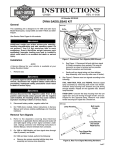
Figure 1. Headlights with Eyebrow Style Mount
Disconnect negative (-) battery cable first. If positive (+)
cable should contact ground with negative (-) cable connected, the resulting sparks can cause a battery explosion,
which could result in death or serious injury. (00049a)
3.
Disconnect battery cables, negative cable first.
-J03106
1 of 5
is00050
is00070
1
2
1
3
4
5
2
6
7
8
3
4
9
1.
2.
3.
4.
5.
6.
7.
8.
9.
5
Headlamp shell
Adapter ring
Connector
Headlamp assembly
Headlamp mount
Washer
Screw
Trim ring
Screw
6
1.
2.
3.
4.
5.
6.
Figure 2. Lower Mount Style Headlamp
4.
Remove the trim ring screw and nut, and remove the trim
ring.
5.
Remove the headlamp lens assembly and disconnect the
wiring connector from the bulb prongs. Save the headlamp.
6.
Remove the adapter ring from the headlamp shell.
NOTE
Note the location of the wires in the connector before removing.
Adjustment screw
Retaining screw (3)
Spring
Headlamp nest
Headlamp
Retaining ring
Figure 3. Headlamp Nest
INSTALLATION
Nacelle Installation
NOTE
Use caution during installation, to prevent scratching the
headlamp nacelle.
1.
See Figure 4. Install spring bracket (2) and screw (3) to
the nacelle. Tighten to 75-100 in-lbs (8.5-11.3 Nm)
7.
Remove the headlamp connectors from the headlamp
harness using a pick tool (Snap-on® TT600-3).
2.
See Figure 3. Install the previously removed headlamp
into the nest using the retaining ring and three screws (2).
8.
Work the wires of the headlamp harness through the
grommet and remove the harness from the headlamp
shell.
3.
Install the assembled headlamp nest into the nacelle using
two adjustment screws.
9.
For Dyna model motorcycles, XL883C and XL1200C
model motorcycles: Remove and discard the headlamp
shell mounting bolt, internal tooth lockwasher and headlamp shell assembly.
4.
Install the wiring harness wires into the headlamp connector in the same locations as noted during the removal
process.
For XL883/L and XL1200R model motorcycles: Remove
and discard the plug, nut, washers and headlamp shell
assembly. Then remove and discard two screws and
washers and headlamp mounting bracket.
10. Remove two screws and the upper triple clamp cover.
Discard removed parts.
11. Cut any cable straps connecting the clutch cable to front
fork or frame.
12. If necessary, re-route the clutch cable outside of the fork.
The clutch cable must be routed outside of the headlight
nacelle.
-J03106
2 of 5
14. Install the left rear cover (1) and the right rear cover (2) to
the nacelle using eight screws (3). Tighten the screws to
10-15 in-lbs (1.1-1.7 Nm).
is00089
2
15. See Headlamp Adjustment below. Check and, if necessary, adjust the headlamp position.
6
is00172
3
7
1
1
2
8
5
1. Spring
2. Spring bracket
3. Screw
4
Figure 4. Spring Bracket
5.
See Figure 4. Connect the spring (1) to the headlamp nest
and the spring bracket (2) on the back of the nacelle.
6.
See Figure 8. Install two metal grommets (8) and screws
(1) to the nacelle. Tighten screws to 10-15 in-lbs (1.1-1.7
Nm).
7.
See Figure 8. Install three screws (15) and the trim ring
bracket (7) to the trim ring (6). Tighten screws to 20-30
in-lbs (2.3-3.4 Nm). Set the assembled parts aside for
later installation.
8.
See Figure 5. Apply 2-3 drops of Loctite® 242 (blue) to the
threads of two screws (6). Install cable guard (7) and
nacelle (8) to the upper triple clamp using two screws (6),
ensuring cable guard locates between the nacelle and
upper fork bracket. Tighten the screws to 10-15 ft-lbs
(13.5-20.3 Nm).
9.
See Figure 5. Apply 2-3 drops of Loctite® 242 (blue) to the
threads of four screws (4). Install two brackets (5) to the
nacelle using the four screws (4). Tighten screws to 2530 ft-lbs (33.9-40.7 Nm).
3
1.
2.
3.
4.
5.
6.
7.
8.
Figure 5. Nacelle and Cover Installation
Headlamp Adjustment
1.
See the Owner's Manual. Verify correct front and rear tire
inflation pressure.
2.
Place motorcycle on level floor (or pavement) in an area
with minimum light.
3.
See Figure 6. Position the motorcycle 25 ft (7.6 m) away
from a screen or wall. Measure the distance from directly
below the front axle to the base of the wall or screen.
4.
Draw a horizontal on the screen or wall, 35 in. (0.9 m)
above the floor.
5.
Load the vehicle with rider, passenger (if normally present)
and any cargo normally carried. Weight will compress the
vehicle suspension slightly.
6.
Stand the motorcycle upright with both tires resting on the
floor and with front wheel held in straight alignment (directly forward).
7.
Turn the ignition/headlamp switch to IGNITION position.
Set handlebar headlamp switch to HIGH beam position.
10. Connect the headlamp connector to the headlamp.
11. Secure loose headlamp wires with cable ties to avoid wear
and damage to the wires.
12. Turn handlebars back and forth, from stop to stop, and
check for cable binding or wire pinching. Adjust the wires
or cables as necessary to correct any binding or pinching.
Connect positive (+) battery cable first. If positive (+) cable
should contact ground with negative (-) cable connected,
the resulting sparks can cause a battery explosion, which
could result in death or serious injury. (00068a)
Cover, left side
Cover, right side
Screw, cover (6)
Screw, nacelle bracket (4)
Bracket, nacelle (2)
Screw, cable gaurd (2)
Cable gaurd
Nacelle
13. Reconnect the battery cables. Connect the positive (+)
cable first.
-J03106
3 of 5
8.
Check and the light beam for proper adjustment:
a.
b.
9.
The main beam of light (broad, flat pattern of light)
should be centered equally above and below the
horizontal lone on the screen or wall.
is00114
1
3
3
The main beam of the light should be directed straight
ahead. Properly adjusted headlamps project an equal
area of light to the left and right of center.
2
If necessary, adjust the headlamp beam as follows:
a.
See Figure 6. Raise or lower the headlamp beam, as
necessary, by turning the vertical adjusting screw (1).
Turn the screw clockwise to raise the beam or counterclockwise to lower the beam.
b.
See Figure 6. Adjust the headlamp beam left or right,
as necessary, by turning the horizontal adjusting
screw (2). Turn the screw clockwise to adjust the
beam towards the rightside of the motorcycle or
counterclockwise to adjust the beam towards the
leftside of the motorcycle.
1. Vertical adjustment screw
2. Horizontal adjustment screw
3. Trim ring mounting grommet (2)
Figure 6. Headlamp Adjustment
10. Turn the ignition/headlamp switch to OFF position.
Final Assembly
1.
See Figure 6. Install trim ring over grommets (3) and turn
the trim ring counterclockwise until the trim ring retaining
screw can be threaded into the nacelle.
2.
Thread trim ring retaining screw to secure the trim ring to
the nacelle. Tighten screw to 20-30 in-lbs (2.3-3.4 Nm).
is00206
NOTE
If the clutch cable is not routed as shown, damage to the
nacelle or clutch cable may occur.
3.
See Figure 7. Route the clutch cable to the rear of the
headlight nacelle as shown.
Figure 7. Clutch Cable Routing
-J03106
4 of 5
SERVICE PARTS
is00042
8
1
15
7
1
8
11
15
12
6
13
9
5
16
2
3
1
9
2
14 10
4
1
Figure 8. Service Parts for Chrome Headlight Nacelle
Table 1. Service Parts Table
Item
Description (Quantity)
Part Number
1
Screw, socket head, chrome, #6-32 x 1/2 in. (10)
3410
2
Screw, hex head, 3/8-16 x 3/4 in. (4)
4713W
3
Headlight nacelle, chrome
Not Sold Separately
4
Cover, back, right, chrome
68179-04
5
Cover, back, left, chrome
68182-04
6
Trim ring, nacelle, chrome
68190-04
7
Bracket, trim ring retaining, chrome
68194-04
8
Grommet, trim ring (2)
68201-04
9
Bracket, nacelle, chrome (2)
68202-04
10
Bracket, spring
68203-04
11
Cable guard
68338-04
12
Screw, button head, chrome, #8-32 x 3/4 in.
94380-92T
13
Screw, button head, chrome, 5/16-18 x 3/4 in. (2)
94393-92T
14
Screw, button head, chrome, 1/4-20 x 1/2 in.
94407-94T
15
Screw, button head, chrome, #8-32 x 3/8 in. (3)
94634-99
16
Headlight nest, with retaining ring, spring, adjustment screws and mounting screws
68204-04
-J03106
5 of 5