1
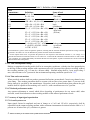
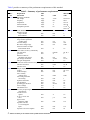
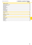
3.2.8
3.2.9
3.2.10
3.2.11
3.2.12
3.2.13
3.2.14
3.2.15
3.2.16
displacement slope
error in lead
weighting factors
hysteresis after 15-mm
deflection from baseline
Standardizing voltage:1)
nominal value
rise time
decay time
amplitude error
Input impedance at
10Hz (each lead)
DC current (any input lead)
DC current (any other patient
electrode)
Common mode rejection:
allowable noise with 20 V,
60 Hz & ± 300 mV dc &
51-kilohm imbalance
System noise:
RTI, p-p
multichannel crosstalk
Baseline control and stability:
retun time 10 s
after reset
return time after
lead switch
Baseline stability:
baseline drift
rate RTI
total baseline drift
RTI (2-min period)
Overload protection:
No damage from differential
voltage, 60-Hz, 1 - V p-p,
10-s application
No damage from sumulated
defibrillator discharges:
overvoltage
energy
recovery time
energy reduction by
defibrillator shunting
transfer of charge through
defibrillator chassis
ECG display in presence
of pacemaker pulses:
amplitude
pulse duration
rise time
frequency
Risk current (isolated
patient connection)
Auxillary output (if
provided):
no damage from short circuit
risk current (isolated
patient connection)
max
mV/s
0.30
max
%
5
max
mm
0.5
NA
max
min
max
mV
ms
s
%
1.0
1
100
±5
min
max
megohms
µA
2.5
0.1
max
µA
1.0
max
max
mm
mV
10
1
max
max
µV
%
30
2
max
s
3
max
s
1
max
µV/s
10
max
µV
500
min
V
1
NA
NA
max
V
J
s
5000
360
8
max
%
10
max
µC
100
range
range
max
max
mV
ms
µs
pulses/min
2 to 250
0.1 to 2.02)
100
100
as per applicable document 2.1.1
as per applicable document 2.1.1
© 2000 Association for the Advancement of Medical Instrumentation