1
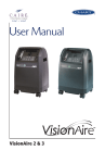
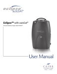
Companion 5 Oxygen Concentrator PROVIDER TECHNICAL MANUAL Table of Contents General Information............................................................. 3 Warning and Caution Statements...................................... 3 Preventive Maintenance—Provider................................... 20 Introduction..................................................................... 20 Maintenance Check List................................................... 20 Introduction to the Companion 5 Oxygen Concentrator... 4 Companion 5 Oxygen Concentrator Specifications............ 5 Provider Support Policy........................................................ 6 Electromagnetic Compatibility............................................. 7 Guidance and Manufacturer’s Declaration - electromagnetic emissions..................................................................... 7 Guidance and manufacturer’s declaration–electromagnetic immunity..................................................................... 8 Guidance and manufacturer’s declaration–electromagnetic immunity..................................................................... 9 Recommended separation distances between portable and mobile RF communications equipment and the Companion 5....................................... 10 Theory of Operation........................................................... 11 Introduction..................................................................... 11 Pressure Swing Adsorption.............................................. 11 Flow Delivery................................................................... 12 Electrical Operation ......................................................... 12 Microprocessor................................................................ 13 4-Way Solenoid Valve...................................................... 13 LCD Display..................................................................... 13 Audible Alarm................................................................. 13 LED Lights........................................................................ 13 OCSI Sensor – (OCSI units only) ...................................... 14 Serial Number Identification............................................. 14 End of Life....................................................................... 14 User Controls And System Status Indicators..................... 15 Indications for Use.............................................................. 16 Contraindications................................................................ 16 Introduction ........................................................................ 16 Pre-Delivery Check List..................................................... 16 Using Around the House.................................................. 17 Locating the Companion 5 for Proper Use and Ventilation.17 Power On and Warm Up.................................................. 17 Adjust Flow Control Rate................................................. 18 Maintenance–Patient.......................................................... 19 Clean and Care for Tubing and Cannula..................................................................... 19 Clean the Cabinet............................................................ 19 Patient Training Checklist................................................. 19 Maintenance Schedule........................................................ 20 Preventive Maintenance Check list................................... 20 Oxygen Concentration Check.......................................... 20 Maintenance Procedures.................................................... 21 Oxygen Concentration Test.............................................. 22 Record Hours of Operation.............................................. 23 Hour Meter...................................................................... 23 Cleaning the Companion 5 ............................................. 23 Shipping and Transporting the Companion 5............................................................. 23 Storing the Companion 5................................................ 23 Discarding....................................................................... 23 Provider Service and Maintenance Record........................ 24 Troubleshooting, Service, and Repair Procedures............. 25 Troubleshooting Table...................................................... 26 Alarm Conditions and Alarm Codes................................... 28 Warning Alarms............................................................... 28 Outer Case...................................................................... 30 Outlet Pressure Test......................................................... 31 Flow Rate Test.................................................................. 32 Start-up Verification Test.................................................. 33 Power Failure Alarm Test.................................................. 33 Product Regulator Check and Setting............................... 33 Adjusting the Product Regulator for Normal Operation................................. 33 Pressure Regulator Replacement...................................... 33 Flapper (Check) Valve....................................................... 34 Compressor .................................................................... 34 Printed Circuit Board (PCB).............................................. 35 4-Way Solenoid Valve...................................................... 35 Sieve Bed Assembly......................................................... 36 Cooling Fan..................................................................... 36 Power Switch .................................................................. 37 Flow Meter ..................................................................... 37 Power Cord..................................................................... 37 Leak Testing..................................................................... 37 Parts Price List...................................................................... 38 Optional Accessories........................................................ 39 CAIRE Inc. Customer Service Contact Information............ 40 Oxygen Concentrator General Information This technical manual will familiarize you with Provider-specific information regarding the Companion 5 oxygen concentrator. Instructions in this manual are intended to help ensure that: • Providers are familiar with Companion 5 system components and system principles of operation • Providers are given proper guidance in the use of the Companion 5 and its accessories that can be conveyed to patients • Providers are made aware of the care, diagnostics, maintenance, and repair of the Companion 5 Warning and Caution Statements Safety instructions are defined as follows: WARNING: CAUTION Note: Important safety information for hazards that might cause serious injury. Important information for preventing damage to the Companion 5. Places emphasis on an operating characteristic or important consideration. PN 14940837 B — 3 Oxygen Concentrator Introduction to the Companion 5 Oxygen Concentrator Companion 5 FRONT Power Switch Outer Case Oxygen Outlet Barb LED Display LCD Display Humidifier Bottle Support Stand (Bottle optional) Flow Meter BACK Air Inlet Exhaust Vent Air Inlet PN 14940837 B — 4 Oxygen Concentrator Companion 5 Oxygen Concentrator Specifications Dimensions (H x W X D) 21.5 x 12.5 x 13.5 inches (54.6cm x 31.8cm x 34.3cm) Weight Companion 5 36.0 lb (16.3 kg) Flow Settings Continuous Flow (measured in Liters Per Minute LPM) 0.5 to 5.0 LPM Continuous Flow Accuracy +/- 10% or 200ml/min, whichever is greater Oxygen Concentration 90% (+5.5/-3%) for all flow settings Oxygen Output Pressure 4.6 psig (31.7 kPa) nominal Green Light = Normal Operation LED Status Indicators Red = Indicates flow rate error, loss of power, ambient pressure reading out of range, or general system malfunction. Yellow Light = Poor Oxygen Concentration below 85% (OCSI models only) Nominal Sound Level 2.0 LPM Continuous Flow Operating Environment Temperature Humidity 40 dB(A) 41º F to 104º F (5° to 40°C) 10% to 95%, Non-condensing, 82.4°F (28°C) Maximum Dew point Storage Environment Temperature -40º F to 158º F (-40° to 70°C) Humidity Up to 95% Non-condensing Altitude Operating Range -1253 to 9878 ft (-382 to 3010 m) Nominal Power 250 watts at 2.0 LPM, 350 Watts Maximum Fuse Rating 230VAC unit: T4AL, 250V 120VAC unit: T8AL, 250V Continuous Flow Indication Expressed in liters per minute (LPM) Audible Alarm Indicators See ALARM CONDITION AND ALARM CODES Back-Up Alarm Power Capacitor Filters HEPA, Compressor Intake Filter Device Classification IEC Class II, Type BF Applied Part, IPX1 Note: To ensure there is no power to the Companion 5 oxygen concentrator, please unplug cord. PN 14940837 B — 5 Oxygen Concentrator Independent Safety Testing Safety IEC 60601-1 :1988 + A1 :1991 + A2 :1995 + Corrigendum (6/95) EN 60601-1(1990) + A1(1993) + A2(1995) + A12(1993) + A13(1996) + Corrigenda (7/94) Electromagnetic Compatibility FCC 15B (Sec. 107 & 109), EN55011, EN60601-1-2 :2001, EN61000-3-2, EN61000-3-3, IEC61000-4-2, IEC61000-4-3, IEC61000-4-4, IEC61000-4-5, IEC61000-4-6, IEC61000-4-8, IEC61000-4-11, IEC 60601-1-2 :2001 The CAIRE Companion 5 is designed to comply with the following standards: • EN 60601-1-2—Electromagnetic Compatibility • IEC 60601-1—General Requirement for Basic Safety of Electrical Medical Equipment • ISO 8359—Oxygen Concentrators For Medical Use • ISO 13485—Medical Device Quality System • UL 60601-1 – General Requirement for Basic Safety of Electrical Medical Equipment It is classified as Class 2 Medical Device by the United States Food and Drug Administration (FDA) and as a Class IIA device by the European Medical Device Directive (MDD). Provider Support Policy Objective: As a manufacturer our organizational goal is to provide customer support and assistance to the highest level of excellence. Customers are Providers (which include Dealers, Distributors and Agents). Support includes, but is not limited to, troubleshooting and Return Material Authorizations (RMA). Business Hours are Monday – Friday, 8:30am – 5:00pm EST. CAIRE Inc. can only support customers who are recognized as Providers, Dealers, Distributors and/or Agents. These partnerships are qualified as having an existing account or are in the process of credit application completion. All patient or enduser inquiries including but not limited to RMA, warranty or serial number questions must be handled by their Provider. Provider Support Policy: CAIRE Inc. is unable to provide direct assistance, clinical advice or recommendations to a patient or enduser. Providers have sole responsibility in assisting their patients. PN 14940837 B — 6 Oxygen Concentrator Electromagnetic Compatibility Medical Electrical Equipment needs special precautions regarding EMC and needs to be installed and put into service according to the EMC information provided in this manual. Portable and mobile RF communications equipment can affect Medical Electrical Equipment. The use of Accessories, transducers, and cables other than those specified, with the exception of transducers and cables sold by the Manufacturer of this device as replacement parts for internal components, may result in increased Emissions or decreased Immunity of the Companion 5. The Companion 5 should not be used adjacent to or stacked with other equipment and that if adjacent or stacked use is necessary, the Companion 5 should be observed to verify normal operation in the configuration in which it will be used. Guidance and Manufacturer’s Declaration - electromagnetic emissions The Companion 5 is intended for use in the electromagnetic environment specified below. The customer or the user of the Companion 5 should assure that it is used in such an environment. Emissions Test RF emissions EN 55011 RF emissions EN 55011 Compliance Group 1 Electromagnetic environment - guidance The Companion 5 uses RF energy only for its internal function. Therefore, its RF emissions are very low and are not likely to cause any interference in nearby electronic equipment. Class B Harmonic emissions IEC 61000-3-2 Class A Voltage fluctuations/ flicker emissions IEC 61000-3-3 Complies The Companion 5 is suitable for use in all establishments, including domestic establishments and those directly connected to the public low - voltage power supply network that supplies buildings used for domestic purposes. PN 14940837 B — 7 Oxygen Concentrator Guidance and manufacturer’s declaration–electromagnetic immunity The Companion 5 is intended for use in the electromagnetic environment specified below. The customer or the user of the Companion 5 should assure that it is used in such an environment. Immunity test IEC 60601 test level Compliance level Electromagnetic environment – guidance Electromagnetic environment – guidance ±6 kV contact ±6 kV contact ±8 kV air ±8 kV air Floors should be wood, concrete or ceramic tile. If floors are covered with synthetic material, the relative humidity should be at least 30 %. Electrical fast transient/burst ±2 kV for power supply lines ±2 kV for power supply lines Mains power quality should be that of a typical commercial or hospital environment. IEC 61000-4-4 ±1 kV for input/output lines N/A Surge ±1 kV line(s) to line(s) ±1 kV line(s) to line(s) IEC 61000-4-5 ±2 kV line(s) to earth ±2 kV line(s) to earth Voltage dips, short interruptions and voltage variations on power supply input lines IEC 61000-4-11 <5 % UT <5 % UT (>95 % dip in UT ) (>95 % dip in UT ) for 0,5 cycle for 0,5 cycle 40 % UT 40 % UT (60 % dip in UT ) (60 % dip in UT ) for 5 cycles for 5 cycles 70 % UT 70 % UT (30 % dip in UT ) (30 % dip in UT ) for 25 cycles for 25 cycles <5 % UT <5 % UT (>95 % dip in UT ) (>95 % dip in UT ) for 5 sec for 5 sec 3A/m 3A/m IEC 61000-4-2 Power frequency (50/60 Hz) magnetic field IEC 61000-4-8 Mains power quality should be that of a typical commercial or hospital environment. Mains power quality should be that of a typical commercial or hospital environment. If the user of the Companion 5 requires continued operation during power mains interruptions, it is recommended that the Companion 5 be powered from an uninterruptible power supply or a battery. Power frequency magnetic fields should be at levels characteristic of a typical location in a typical commercial or hospital environment. NOTE UT is the a.c. mains voltage prior to application of the test level. PN 14940837 B — 8 Oxygen Concentrator Guidance and manufacturer’s declaration–electromagnetic immunity The Companion 5 is intended for use in the electromagnetic environment specified below. The customer or the user of the Companion 5 should assure that it is used in such an environment. Immunity test IEC 60601 test level Compliance level Electromagnetic environment – guidance Portable and mobile RF communications equipment should be used no closer to any part of the Companion 5, including cables, than the recommended separation distance calculated from the equation applicable to the frequency of the transmitter. Recommended separation distance Conducted RF 3 Vrms IEC 61000-4-6 150 kHz to 80 MHz Radiated RF 3 V/m IEC 61000-4-3 80 MHz to 2,5 GHz 3 Vrms 3 V/m d = 1.2 P d = 1.2 P 80 MHz to 800 MHz d = 2.3 P 800 MHz to 2,5 GHz where P is the maximum output power rating of the transmitter in watts (W) according to the transmitter manufacturer and d is the recommended separation distance in metres (m). Field strengths from fixed RF transmitters, as determined by an electromagnetic site survey, ashould be less than the compliance level in each frequency range. b Interference may occur in the vicinity of equipment marked with the following symbol: NOTE 1 At 80 MHz and 800 MHz, the higher frequency range applies. NOTE 2 These guidelines may not apply in all situations. Electromagnetic propagation is affected by absorption and reflection from structures, objects and people. Field strengths from fixed transmitters, such as base stations for radio (cellular/cordless) telephones and land mobile radios, amateur radio, AM and FM radio broadcast and TV broadcast cannot be predicted theoretically with accuracy. To assess the electromagnetic environment due to fixed RF transmitters, an electromagnetic site survey should be considered. If the measured field strength in the location in which the Companion 5 is used exceeds the applicable RF compliance level above, the Companion 5 should be observed to verify normal operation. If abnormal performance is observed, additional measures may be necessary, such as re-orienting or relocating the Companion 5. a b Over the frequency range 150 kHz to 80 MHz, field strengths should be less than 3 V/m. PN 14940837 B — 9 Oxygen Concentrator Recommended separation distances between portable and mobile RF communications equipment and the Companion 5 The Companion 5 is intended for use in an electromagnetic environment in which radiated RF disturbances are controlled. The customer or the user of the Companion 5 can help prevent electromagnetic interference by maintaining a minimum distance between portable and mobile RF communications equipment (transmitters) and the Companion 5 as recommended below, according to the maximum output power of the communications equipment. Rated maximum output power of transmitter Separation distance according to frequency of transmitter m 150 kHz to 80 MHz d = 1.2 P 80 MHz to 800 MHz d = 1.2 P 800 MHz to 2,5 GHz d = 2.3 P 0,01 0.12 0.12 0.23 0,1 0.38 0.38 0.73 1 1.2 1.2 2.3 10 3.8 3.8 7.3 100 12 12 23 W For transmitters rated at a maximum output power not listed above, the recommended separation distance d in metres (m) can be estimated using the equation applicable to the frequency of the transmitter, where P is the maximum output power rating of the transmitter in watts (W) according to the transmitter manufacturer. NOTE 1 At 80 MHz and 800 MHz, the separation distance for the higher frequency range applies. NOTE 2 These guidelines may not apply in all situations. Electromagnetic propagation is affected by absorption and reflection from structures, objects and people. PN 14940837 B — 10 Oxygen Concentrator Theory of Operation Introduction The Companion 5 is a stationary medical device used to extract oxygen from the atmosphere, concentrate it, and present the oxygen to the patient. The device will operate in Continuous Flow Mode. In Continuous Flow Mode the oxygen is provided at a constant flow rate between 0.5 and 5.0 LPM (Continuously Variable). Table 2 below lists the major internal components of the concentrator and their functions. Reference Table 2 and Figure 3 (on the following page) for clarification while reading the Theory of Operation Section of the manual. Item Function Intake Filter Provides HEPA level filtration for intake to compressor. Compressor Pump that routes air into and through the concentrator. Cooling Fan Cools the compressor area. 4-Way Solenoid Valve Routes air flow through one sieve bed and vents the purged air to the atmosphere from the other bed. Responsible for alternating flow between the beds. Sieve Beds (2) Chemically adsorbs nitrogen molecules from the air. Orifice Routes a larger portion of air exiting one sieve bed back through the other bed for purging. Flapper Valve Routes a smaller portion of air exiting one sieve bed into the product holding tank. Prevents back flow from product tank to sieve bed Product Holding Tank Holds concentrated oxygen prior to its regulation and delivery to the patient. Pressure Regulator Reduces the outlet pressure to be compatible with the flow meter and accessories. OCSI Sensor Detects oxygen concentration of flow exiting the concentrator (OCSI models only). Sends a signal to activate alarm if concentration is too low. Flow Control Valve Integral needle valve that controls volumetric flow (LPM) to the patient. Is read against the printed scale. HEPA Filter HEPA level filtration of outlet flow. Printed Circuit Board (PCB) Responsible for all of the electrical operation of the concentrator. Contains a programmable microprocessor that controls valve timing, alarm indications, and OCSI functions (if applicable). Pressure Swing Adsorption The CAIRE Companion 5 utilizes the Pressure Swing Adsorption (PSA) Process to concentrate oxygen gas from ambient air. In the PSA process, a compressor draws ambient air into the machine through an intake filter. The compressor then forces the filtered air into a solenoid valve which directs the air into one of two tanks that are full of a molecular sieve material, referred to as sieve beds. As the pressure in sieve bed 1 increases, nitrogen molecules are removed from the ambient air and are stored in the sieve material. The gas that exits sieve bed 1 is highly-concentrated oxygen. The majority of this gas flows through an orifice to sieve bed 2 and is used to purge the stored nitrogen gas from its sieve material. The remainder of the oxygen gas is directed through a flapper valve to the product holding tank. Here, it is stored for delivery to the patient. Sieve bed 1 continues to pressurize until the sieve material is completely saturated with nitrogen. At this time the printed circuit board (PCB) switches the state of the solenoid valve, dumping pressurized air in sieve bed 1 back into the atmosphere via the purge muffler. Simultaneously, the valve now directs the compressed air into sieve bed 2, which has been completely purged of nitrogen gas and is ready for nitrogen adsorption/oxygen concentration. This cycle continuously repeats pressurizing and depressurizing the sieve beds, feeding concentrated oxygen to the product holding tank. Table 2: Internal Components of Concentrator PN 14940837 B — 11 Oxygen Concentrator Flow Delivery Electrical Operation Oxygen exiting the product holding tank flows through a pressure regulator that reduces the high pressure oxygen to a lower, more manageable pressure before it is delivered to the patient. This ensures that the oxygen flowing from the device will work appropriately with accessories and provide a safe pressure for patient delivery. All electrical components of the CAIRE Companion 5 are all controlled by a PCB. The electrical cord supplies mains AC power (120 VAC @ 60 Hz or 230 VAC @ 50 Hz) to the main circuit board when the power switch is in the “ON” (|)position. The PCB distributes the mains power to all of the electrical components. The AC mains power is distributed and routed directly to the compressor and the cooling fan. The compressor and cooling fan both operate at 120 VAC @ 60 Hz or 230 VAC @ 50 Hz. The remaining power travels to a DC power convertor/regulator. Figure 4 is a block diagram showing the flow and distribution of mains power into the concentrator. The Companion 5 oxygen concentrator may be equipped with an Oxygen Concentration Status Indicator (OCSI). In that case, oxygen gas exiting the pressure regulator flows through a check valve and then through the OCSI sensor. This is the same area of the concentrator where the flow is measured. The PCB monitors the concentration and the flow measured by these sensors, and it will activate a warning light and audible alarm if the concentration drops below predetermined levels described in the Warning Alarms section of the manual. or After exiting the concentration and flow rate sensors, oxygen flows through the flow control valve (FCV) at the LPM flow rate selected by the patient and indicated on the flow meter. The oxygen gas then flows through the HEPA filter where unwanted contaminants are removed. The oxygen is then delivered to the patient through the outlet barb. or or Figure 4: Diagram of Mains Electrical Distribution Figure 3: Schematic Diagram of Pneumatic Operation PN 14940837 B — 12 Oxygen Concentrator Microprocessor 4-Way Solenoid Valve The microprocessor is the only processing element of the CAIRE Companion 5. It contains embedded software which is programmed with all of the parameters for alarm conditions and settings of the concentrator. The microprocessor is directly responsible for the following functions of the concentrator: The solenoid valve is connected to the circuit board’s microprocessor by a 4-pin connector. The microprocessor is responsible for sending the signal to open and close the valves. This cycles the air through alternating sieve beds for the PSA process. The timing for alternating the sieve beds is programmed into the microprocessor. • Cycling (timing) of the 4-way solenoid valve • Driving the LCD display • Controlling the audible alarm • Controlling the operational and warning LED lights • Reading input from the OCSI sensor (OCSI models only) The microprocessor is programmed with the alarm thresholds and trigger points, as well as the timing of the 4-way solenoid valve to cycle between sieve beds. A diagram of the input and output of the microprocessor is shown below in Figure 5. Each input and output is described further in the following sections. LCD Display The 6-digit digital LCD display is mounted on the PCB and is visible on the front of the concentrator. Its purpose is to continually count and display the hours that the concentrator has been in operation and to display alarm conditions. The LCD display cannot be re-set and displays time to the nearest tenth of an hour. Audible Alarm The CAIRE Companion 5 contains an audible buzzer that is surface mounted on the PCB. Its purpose is to alert users of alarm conditions. The microprocessor detects alarms by reading the input from the OCSI sensor and the mains power switch. When there is an alarm condition, the microprocessor sends a signal to activate the audible alarm. LED Lights There are two (2) or three (3) (OCSI) LED lights that are surface mounted on the PCB. They are visible from the front of the concentrator and their purpose is to alert the user of operating conditions or alarms. The top LED indicator is green. It remains on at all times when the power switch is in the “ON” (|) position and the electrical cord is plugged in. A continuous green light indicates normal operation. The next LED indicator will be red. This light will indicate malfunctions with the device. When the microprocessor detects an alarm condition from the power switch or the flow rate sensor, it will send a signal for the red LED to illuminate. The red LED will indicate a system malfunction, loss of power, or flow rate is out of specifications. Figure 5: Microprocessor Operation Block Diagram The bottom LED indicator will be yellow (OCSI Models only). This light will only indicate low oxygen concentration. This LED will illuminate when the microprocessor detects an alarm condition from the OCSI sensor. The LED will be solid if the oxygen concentration is 70%-85%, and it will flash if the concentration is less than 70%. The warning alarms section will describe these alarm conditions in detail, and provide basic troubleshooting steps. PN 14940837 B — 13 Oxygen Concentrator OCSI Sensor – (OCSI units only) Serial Number Identification The OCSI sensor detects the oxygen concentration of the air The serial number of the CAIRE Companion 5 is located on the being delivered to the patient. The sensor consists of an intake back label of the outer case. The serial number is in the middle of and outlet port on each end of a flow path that is encased in an the label, just below the bar code. A sample label is shown below. air-tight cover. The microprocessor determines concentration from the OCSI sensor output, and activates alarms when appropriate. The limits for alarm conditions are programmed into the software of the microprocessor and are described in the Warning Alarms section of this manual. The concentrator takes several minutes to build internal pressure and concentration. This is known as the warm-up period, and the signal from the sensor is ignored by the PCB for ten (10) minutes. This means that the alarms associated with the OCSI will not activate until this predetermined amount of time has passed. Figure 7: Serial Number Label End of Life At the end of the service life of the CAIRE Companion 5, it should be disposed of in accordance with local regulations. PN 14940837 B — 14 Oxygen Concentrator User Controls And System Status Indicators Symbol 02 Definition Symbol Read user manual before operation. See user manual for instructions. I/O Definition On/Off Switch No Smoking Icon: Do not smoke near unit. Use no oil or grease. Warnings / ALERT (Yellow) Indicator No open or naked flames. Class II equipment No serviceable parts inside. Do not open cover. Oxygen Output Certified for both the U.S. and Canadian markets, to the applicable U.S. and Canadian standards. Type BF Applied Part (degree of protection against electric shock) This device complies with the requirements of Directive 93/42/EEC concerning medical devices. It therefore bears the CE marking as shown. This symbol is to remind the equipment owners to return it to a recycling facility at the end of its life, per Waste Electrical and Electronic Equipment (WEEE) Directive. Authorized representative in the European Community IPX1 Drip Proof Equipment-IPX1: The Companion 5 provides protection against the harmful effects of the ingress of liquids. (IPX1, per IEC 60529) Name and address of manufacturer Buzzer: An audible alarm (or buzzer) is used to alert you to the operating condition of the device, either a warning or failure. PN 14940837 B — 15 Oxygen Concentrator Indications for Use Introduction The Companion 5 is indicated for the administration of supplemental oxygen. The device is not intended for life support nor does it provide any patient monitoring capabilities. Welcome to the CAIRE Companion 5 oxygen concentrator. Setting up and training your patient to use the Companion 5 has never been easier! You can expect your patients and care providers to easily learn how to use the device by following the directions in this section. While setting up and training a patient, be sure to point out the advantages of the Companion 5. For example: A physician must prescribe a specific oxygen flow rate setting to meet patients’ individual needs. Recommended oxygen flow rates should be adjusted only under the advice of a physician. WARNING: Federal law restricts this device to sell by or on the order of a physician. Contraindications WARNING: WARNING: WARNING: WARNING: The Companion 5 is not intended for life supporting or life sustaining applications, nor does it provide any patient monitoring capabilities. In certain circumstances, the use of non-prescribed oxygen can be hazardous. This device should only be used when prescribed by a physician. Not for use in the presence of flammable anesthetics. As with any electrically powered device, the user may experience periods of non-operation as a result of electrical power interruption, or the need to have the Companion 5 serviced by a qualified technician. The Companion 5 is not appropriate for any patient who would experience adverse health consequences as a result of such temporary interruption. • Easy-to-use controls • Quiet operation • Self-monitoring alarm system After completing each training procedure, ask your patient if he or she has any questions. Proper training of your patients will result in fewer service calls, improved compliance and increased patient satisfaction. Pre-Delivery Check List Verify that the Companion 5 is provided to the patient with the following items: Users’ Manual Required Oxygen Delivery Accessories (Cannula, Tubing, Humidifier, etc.) Power - Insert the AC power cord into an electrical outlet to check for proper operation Before delivering the device, check and log the status of the following using the LCD Display: Hours on the hour meter Software Revision (The LCD Display will show this upon startup) You may adjust the liter flow settings to your patient’s prescription when you deliver and set up the device. Connecting the AC Power The Companion 5 operates from external power. 1. Plug the power cord into an AC outlet. 2. The Companion 5 is now ready for use. Note: If the Companion 5 is not receiving power when it is turned on, the unit will alarm and display a solid red light. WARNING: Ensure adequate clearance around the AC Cord. PN 14940837 B — 16 Oxygen Concentrator CAUTION • DO NOT connect the Companion 5 to an extension cord or electrical outlet controlled by a switch. • Always check to see that the Air Inlet and the Exhaust Vent are not blocked. Disconnecting the AC Power To ensure that there is no power to the Companion 5, unplug from AC power. Note: Turn the Companion 5 to the “Off” (O) position to avoid alarming before disconnecting the AC Power cord. Note: After completing this training procedure, ask your patient if he/she has any questions. Power On and Warm Up Plug the electrical cord of the CAIRE Companion 5 into an AC outlet. WARNING: Inspect the electrical cord for damage before use. If the cord is damaged, do not plug it into an electrical outlet or attempt to operate the concentrator. Using Around the House Your patient may use 50’ tubing when operating the Companion 5 in the house. When a humidifier is used, the tubing between it and the patient must not exceed 7’. CAUTION When using a humidifier adapter of any kind, the Companion 5 unit must remain stationary, meaning that the unit must NOT be moved or transported in any manner to avoid damage to the Companion 5. Press the power switch in the “ON” (I) position. Locating the Companion 5 for Proper Use and Ventilation Ask your patient where they would like to set up the device. Whenever possible, the Companion 5 should be in the same room as the patient for convenience and assurance that the patient can adequately hear and respond to Companion 5 alerts and alarms. While unpacking and setting up the device, tell your patient about these important cautions and warnings: Warning: Locate the Companion 5 in a well-ventilated space that provides adequate airflow. Warning: Ensure that furniture, draperies or clothing will not impede air circulation. Warning: Avoid placing the unit over a floor heat register or against a baseboard heating system. Warning: Do not use in the presence of flammable anesthetics, solvents, aerosols or flammable cleaning agents. Warning: Avoid high pollutant environments. CAUTION When the Companion 5 is plugged in properly and turned on, a green indicator on the LED Display will light up. After initially powering ON the device, please allow up to ten (10) minutes for the device to reach its performance specifications. Note: All LED lights will illuminate upon start-up. After the concentrator completes the warm-up cycle, only the green light will remain on. For OCSI Models: The O2 Light will illuminate for four (4) seconds upon start-up. After this initial start-up, this light is disabled for approximately ten (10) minutes while the concentration rises to specifications. The warm-up period could be up to 10 minutes. After this time, only the green LED remains lit to indicate normal operation. Some patients are highly mobile and may use the device under varying circumstances. Make sure your patient or patient caregiver completely understands the basic precautions to safely locate the device. PN 14940837 B — 17 Oxygen Concentrator Adjust Flow Control Rate Turn the flow control knob to the oxygen flow rate (LPM) prescribed by your physician. To adjust flow rate: Turn counter-clockwise to increase flow. Turn clockwise to decrease flow. The middle of the ball indicates flow rate. There are two sets of lines (front and back). In the example below, the flow meter would read “4LPM”. WARNING: It is very important to select only the prescribed level of oxygen. Do not change the flow selection unless you have been directed to do so by a licensed clinician. The Oxygen Concentrator may be used during sleep under the recommendation of a qualified clinician. PN 14940837 B — 18 Oxygen Concentrator Maintenance–Patient Clean and Care for Tubing and Cannula Provide your patient instructions on cleaning, disinfection and/or replacement information for the tubing and cannula. 3. Use a damp (not soaking wet) cloth or sponge. 4. Spray or wet the cloth or sponge with the mild detergent solution. DO NOT spray the cabinet. 5. Wipe down the cabinet. 6. To disinfect the Companion 5, use Lysol® Brand II disinfectant (or equivalent). Spray or wet a cloth or sponge with the disinfectant. DO NOT spray the cabinet or the LED/LCD display. Proceed as directed by the manufacturer. Clean the Cabinet To clean the cabinet do the following: 1. Turn OFF the Companion 5 and disconnect from AC power before any cleaning or disinfection activity. 2. Use mild detergent and water solution. Patient Training Checklist Use the following checklist as a guide to assist in setup and training a patient on the use of the Companion 5 and its accessories. Patient Name: Companion 5 Serial #: Training Topic Initials Pre-Delivery Check List Indications for Use Contraindications Basic Concept Training Advise to read the Users Manual Safety Guidelines and Operational Safety Warnings/Cautions Locating the Companion 5 Indicators Alerts and Alarms Companion 5 Maintenance Clean and Care for the Cannula per manufacturer’s instructions. Clean the Cabinet as needed. Schedule PM every 2 years Trained By: Date: PN 14940837 B — 19 Oxygen Concentrator Preventive Maintenance— Provider Introduction Properly maintaining the Companion 5 will ensure longer life and higher performance. Preventative Maintenance is required every 2 years at a minimum. CAUTION The Companion 5 contains electrostatic sensitive components. Do not open or handle except at a static free workstation. Do not remove cover without electrostatic discharge (ESD) protection. Maintenance Check List Perform the following maintenance procedures at least every two years or more often, as needed. The frequency of the periodic maintenance should be based on the environment in which the Companion 5 is used. • Inspect AC Power cord and plug for damage • Read and record hour meter • Check flow rate, concentration, and alarm functions • Replace air intake filter and HEPA filter Maintenance Schedule Preventative Maintenance Check list Perform the following maintenance procedures at least once every two years or more often, as needed. The frequency of the periodic maintenance should be based on the environment in which the Companion 5 is used. Harsh environments may require preventative maintenance more frequently than every 2 years. • Replace air intake filter • Replace HEPA filter Oxygen Concentration Check CAIRE recommends the oxygen concentration be checked periodically as required by the provider. For non-OCSI units, CAIRE recommends a 6 month interval between concentration checks. PN 14940837 B — 20 Oxygen Concentrator Maintenance Procedures 3.Separate the front case from the back case. The following section lists procedures that are necessary to maintain the Companion 5. Service should only be performed by a qualified technician. To perform periodic maintenance, the only tools that should be necessary are: • • • • • • • • • • • • Magnetic tip long-stem #2 Phillips Wire-cutting pliers Small cable ties ESD Mat or approved ESD system Flat head screwdriver Flow Meter/Oxygen Analyzer 3/32” Allen wrench 5/32” Allen wrench Adjustable Pliers Needle Nose Pliers Ohmmeter/Multi-Meter Replacement Filters WARNING: 4. Disconnect the HEPA filter from the outlet barb tubing. 5. Disconnect the HEPA filter from flow meter tubing. Disconnect all power supplies going to the unit prior to performing the following steps HEPA Filter 1. Press the power switch in the “OFF” position and unplug the electrical cord. 2.Use a long-stem Phillips to remove the 6 screws from the back case. Bacteria Filter 6. Remove the filter. 7. To replace, reverse steps 1–7. Note: • Direction of flow on the filter is indicated by the text “IN”. Bacteria filter is flow directional. • In the picture above, “IN” should be facing down or opposite of the flow control valve. WARNING: DO NOT use any petroleum based or other lubricants. A spontaneous and violent ignition may occur if oil, grease or other petroleum substances come into contact with oxygen under pressure. Keep these substances away from the oxygen concentrator, tubing and connections and any other oxygen source. Note: Always cut the heads of cable ties to avoid damaging the tubing. PN 14940837 B — 21 Oxygen Concentrator Intake Filter Oxygen Concentration Test 1.Press the power switch in the “OFF” position and unplug the electrical cord. 2.Lay the concentrator gently on its side to access the bottom of the unit. 3.Remove screw with Phillips Screw Driver from the filter cover. See picture below. CAIRE recommends testing the oxygen concentration at least once every six months for non-OCSI units. 1. Plug the AC Power Cord into an electrical outlet, and turn the power switch in the “ON” (I) position. 2. Allow the concentrator to run continuously for a minimum of 10 minutes. 3. Disconnect the tubing and/or cannula from the outlet barb if one is attached. 4. Turn the flow control knob to 5LPM 5. Connect a calibrated oxygen analyzer to the outlet barb. 6. Verify that this display reads between 87–95.5%. Note: • If the oxygen concentration is not between 87–95.5%, refer to the troubleshooting section of this manual for “Low Oxygen Concentration.” • If the concentrator is alarming and the oxygen concentration measured is greater than 85%, replace the main PCB. Filter Cover 4. Pull outward to remove filter cover. Filter Cover 5. Pull outward on the intake filter to remove from its compartment. 6. To replace, reverse steps 1–5. PN 14940837 B — 22 Oxygen Concentrator Record Hours of Operation Cleaning the Companion 5 To help maintain the Companion 5, you may obtain the total hours of operation. Clean inside the unit, as needed, using a small vacuum cleaner or brush to remove any accumulation of dust or debris prior to attaching the covers. Use mild detergent solution to clean the cabinet. Turn OFF the Companion 5 and disconnect from AC power before any cleanA digital hour meter is mounted on the PCB and is displayed on ing or disinfection activity. DO NOT spray the cabinet. Use a damp the concentrator’s front panel. Its purpose is to continually count (not soaking wet) cloth or sponge. Spray the cloth or sponge with and display the hours that the concentrator has been in operation. a mild detergent solution to clean the cabinet and power supplies. The hour meter cannot be re-set and displays time to the nearest To disinfect the Companion 5, use Lysol® Brand II disinfectant or tenth of an hour. equivalent. Proceed as directed by the manufacturer. Hour Meter WARNING: Disconnect and remove ALL power supply connectors before cleaning the exterior cabinet. DO NOT use denatured alcohol or apply liquid spray or aerosol cleaners. Shipping and Transporting the Companion 5 When shipping the Companion 5, use original packaging if possible. If original packaging material is not available, then place the Companion 5 in a plastic bag and surround the concentrator with a minimum of two inches of soft foam packing material or bubble wrap. Place the Companion 5 in an appropriate cardboard box for shipping. WARNING: DO NOT expose the Companion 5 to water. Electrical shock or damage to the unit may result. Storing the Companion 5 Heat and humidity may degrade performance or severely damage the Companion 5. Store the device in a cool, dry, protected area away from high temperatures, moisture and humidity. Discarding Local environmental laws may prohibit disposal of electrical and/ or electronic equipment such as the Companion 5. Contact the local city or town offices for instructions on proper disposal of electrical or electronic equipment. Alternately, CAIRE Inc. may be contacted for disposal information. PN 14940837 B — 23 Oxygen Concentrator Provider Service and Maintenance Record Whenever maintenance or service is performed on an Companion 5 unit, an entry should be made in the service log for that concentrator or recorded in accordance with your company’s standard procedure. Whenever the case of the Companion 5 is opened, the flow rate, concentration, and alarm status should be verified per the Test Procedures in this manual. Companion 5 Serial Number _________________________________________ Date Hour meter Reading System Checkout Initials Service Performed Concentration Flow Alarms Comments PN 14940837 B — 24 Oxygen Concentrator Troubleshooting, Service, and Repair Procedures CAUTION The Companion 5 contains electrostatic sensitive components. Do not open or handle except at a static free workstation. Do not remove cover without ESD protection. General Troubleshooting Before reviewing the troubleshooting chart, the following steps may be useful to isolate any malfunctions: 1. Turn on the concentrator. If the unit does not turn on, refer to the troubleshooting chart. 2. Allow the unit to warm up for approximately 10 minutes and check oxygen concentration. 3. Perform the flow rate test. Verify flows are within acceptable range per Table 8. 4. Make sure the unit is cycling properly by observing the flow meter ball is stable (flow meter ball does not move up and down more than ¼ liter.) 5. Place your thumb over outlet of unit. The flowmeter ball should drop to the bottom of the flowmeter. If the ball does not drop completely to the bottom, there is a leak present between the top of the flowmeter and the outlet of the unit. 6. If concentrator is not meeting specifications, make sure that the unit is leak-free by testing all tubing connections and fittings with leak testing solution. Protect circuit board(s) from solution and start leak test at the compressor, following air flow to oxygen outlet. Repair all leaks by tightening connections and fittings. 7. If unit is alarming, refer to the Alarm Indicator Chart for probable solutions. PN 14940837 B — 25 Oxygen Concentrator Troubleshooting Table Symptom No Oxygen Flow Possible Cause 1 Oxygen Tubing Kinked/Leaking Check the nasal cannula and any extension tubing being used for kinks, blockages, or leaks. Verify that all tubing connections are secure. Replace and tubing if necessary. 2 Humidifier Bottle Restriction (if used) Check the humidifier bottle and tubing for blockages or restrictions. 3 Flow Meter Closed (off) 4 Low Or Fluctuating Oxygen Flow Rates Internal Tubing Kinked/Leaking Check all internal tubing for leaks. Verify that there are no leaks and that all connections are secure. Replace any tubing or parts if necessary. Inspect the HEPA filter for a blockage. Replace if found to be clogged. 6 Compressor Malfunction Verify that the compressor is operating properly. Replace the compressor if necessary. 1 Oxygen Tubing Kinked/Leaking Check the nasal cannula and any extension tubing being used for kinks, blockages, or leaks. Verify that all tubing connections are secure. Replace any tubing if necessary. 2 Humidifier Bottle Restriction (if used) Check the humidifier bottle and tubing for blockages or restrictions. 3 Poor Concentrator Location Verify that the concentrator is in a well-ventilated location and that air flow into the device is not impeded. 4 Intake Filter Restriction Inspect the intake filter for a blockage. Replace if found to be clogged. 5 Bacteria Filter Restriction Inspect the HEPA filter for a blockage. Replace if found to be clogged. Internal Tubing Kinked/Leaking Check all internal tubing for leaks. Verify that there are no leaks and that all connections are secure. Replace any tubing or parts if necessary. 7 Flow Meter Malfunction Verify the functionality and accuracy of the flow meter. Replace if necessary. 8 Regulator Malfunction Check the outlet pressure. If it is out of the acceptable range, adjust or replace the regulator. 9 Compressor Malfunction Verify that the compressor is operating properly. Replace if necessary. 1 Intake Filter Restriction Inspect the intake filter for a blockage. Replace if found to be clogged. 2 Bacteria Filter Restriction Inspect the Bacteria filter for a blockage. Replace if found to be clogged. 3 Poor Concentrator Location Verify that the concentrator is in a well-ventilated location and that air flow into the device is not impeded. 4 Internal Tubing Kinked/Leaking Check all internal tubing for leaks. Verify that there are no leaks and that all connections are secure. Replace any tubing or parts if necessary. 5 Solenoid Valve Malfunction Verify the operation of the 4-way solenoid valve. Replace if necessary. 6 Compressor Malfunction Verify that the compressor is operating properly. Replace if necessary. 7 Sieve Bed Failure Replace the sieve beds assembly. 1 Poor Concentrator Location Verify that the concentrator is in a well-ventilated location and that air flow into the device is not impeded. 2 Cooling Fan Malfunction Verify that the cooling fan is connected properly to the circuit board and check the continuity of the connection. Replace the cooling fan if it is not functioning. Overheating Outlet Pressure Out of Acceptable Range (4.3 - 4.9 psi). Inspect the flow meter and verify that the ball is not at the bottom of the meter. If it is, turn the knob to increase the flow. Replace the flow meter if necessary. 5 HEPA Filter Restriction 6 Low Oxygen Concentration Corrective Action 1 Internal Tubing Kinked/Leaking Check all internal tubing for leaks. Verify that there are no leaks and that all connections are secure. Replace any tubing or parts if necessary. 2 Regulator Out of Adjustment Adjust the regulator. 3 Regulator Malfunction Replace the regulator. 4 Sieve Bed Failure Replace the sieve beds assembly. PN 14940837 B — 26 Oxygen Concentrator Symptom Constant Audible Buzzer With Red Light (Alarm Code: AL-P02) Will Not Turn On When Power Switch is “ON” (I) LED Lights Will Not Illuminate Audible Alarm Does Not Sound Possible Cause Corrective Action 1 Power Failure Verify that the electrical cord is plugged into an outlet and that there is power being supplied to the outlet. Replace the electrical cord if necessary. 2 Blown Fuse Replace fuse on circuit board. 1 No Power Being Supplied Verify that the electrical cord is plugged into an outlet and that there is power being supplied to the outlet. Also check the household circuit breaker. 2 Power Switch Malfunction Verify that the power switch is plugged into to the main circuit board. Replace the power switch if necessary. 3 Electrical Cord Malfunction Verify that the electrical cord is plugged into to the main circuit board. Replace the electrical cord if necessary 4 Blown Fuse Replace fuse on circuit board. 1 No Power Being Supplied Verify that the electrical cord is plugged into an outlet and that there is power being supplied to the outlet. 2 Circuit Board Malfunction Verify that all connections to the circuit board are intact. Replace the main circuit board if necessary. 3 Blown Fuse Replace fuse on circuit board. 1 Circuit Board Malfunction Verify that all connections to the circuit board are intact. Replace the main circuit board if necessary. PN 14940837 B — 27 Oxygen Concentrator Alarm Conditions and Alarm Codes Use the on the next page to decode Companion 5 alarm conditions. If other alarm codes are displayed by the Companion 5, contact Chart Technical Support for assistance. Note: The following table is intended as a guide for the provider, not the user. Warning Alarms The CAIRE Companion 5 contains both visual and audible alarms to alert the user when there is a malfunction with the unit. The audible buzzer and the LED lights work in conjunction to display operating and alarm conditions of the concentrator. The audible buzzer has the ability to both pulse (beep) and to sound continuously. There are 3 LED warning lights that are visible on the front of the Companion 5: 1) Green LED - Indicates normal operation. Illuminates when power is supplied to the concentrator and the power switch is in the “ON” (I) position. 2) Red LED - Indicates flow rate error, loss of power, ambient pressure reading out of range, or general system malfunction. The concentrator requires service if this light is on, with the exception of “flow rate alarm”. 3) Yellow LED - Indicates poor oxygen concentration below 85% (flashing) or 70% (solid). See the following table for more information. The concentrator requires service if this light is on. Ref 15067540 Rev C Ref 15067558 Rev C LED Display, Non-OCSI left, OCSI right. PN 14940837 B — 28 Oxygen Concentrator The table below shows all of the alarm conditions that can be experienced by the CAIRE Companion 5: Alarm Code Audible Alarm None Off AL-P01 Continuous Red Solid System Malfunction Turn the power switch in the “OFF” position immediately. Disconnect the AC Power from the wall outlet. Wait 5 minutes. Connect the AC Power back into the wall outlet and turn the concentrator back on again. If the alarm continues, service is required. Connect to a backup oxygen supply and contact your healthcare provider immediately. AL-P02 Continuous Red Solid The concentrator has lost power but the power switch is still in the “ON” (I) position. Verify that the concentrator’s electrical cord is plugged into an outlet and that the outlet has power. Try a different outlet. If the problem continues, connect to a back-up oxygen supply and contact your healthcare provider. AL-P20 Beeping Red Flashing Low Product Flow Rate AL-P40 Beeping Red Flashing High Product Flow Rate 1. Ensure that the cannula is not kinked or blocked. If used with a humidifier bottle, ensure that it is filled properly and not creating a blockage. 2. Ensure that the Companion 5 has proper ventilation. Make sure there are at least 12 inches between the back and sides of the Companion and any obstructions (furniture, curtain, etc.) 3. If the problem persists, switch to an alternate source of oxygen and contact healthcare provider for assistance. AL-P04 Beeping Yellow Flashing Failed O2 Alarm Condition (O2 Levels Less Than 70%) AL-P08 Continuous Note: Colored LED Possible Cause Patient Action Green Solid The Companion 5 is None working properly Yellow Solid Poor O2 Alarm Condition (O2 Levels Between 70% and 85%) 1. Ensure the air intake filter is not is not clogged or restricted. 2. Ensure the Companion 5 is in a well-ventilated area. Make sure there are at least 12 inches between the back and sides of the Companion 5 and any obstructions (furniture, curtain, etc.) 3. If the condition persists, switch to an alternate source of oxygen and contact your healthcare provider immediately. Note: The alarm codes will be additive if more than one code is active. For example, if the unit is undergoing a high product flow rate alarm and a poor O2 alarm condition, the alarm code will be P40 + P08 = P48. The concentrator will continue normal operation even though an alarm condition is in effect. The power failure alarm will have the ability to sound for a period after power has been disrupted to the device. The audible alarm is powered by a super capacitor that is charged by the PCB while the concentrator is in operation. It takes the audible alarm approximately 30 minutes to fully charge. The capacitor has a set of contacts that is activated when the power switch is in the “ON” position and no AC power is being supplied. The alarm is stopped by re-supplying power to the concentrator. All other alarms will continue until the alarm condition has been corrected. Service to the concentrator by authorized personnel is recommended anytime an alarm condition is experienced. Procedures for servicing and testing the unit are outlined in the Troubleshooting section of this manual. PN 14940837 B — 29 Oxygen Concentrator Repair and Testing Procedures The following test and repair procedures have been developed to allow for both performance verification of the CAIRE Companion 5 as well as proper removal and replacement of defective parts. If a unit fails any given test, refer to the Troubleshooting section of the manual. 1.Use a long-stem Phillips to remove the 6 screws from the back case. Please carefully read and understand the following safety advisories before performing repair procedures. WARNING: CAUTION Note: • Verify that the power switch is in the “OFF” position and the electrical cord is unplugged before performing any repairs unless otherwise noted. • Make sure your hands are free of oils and greases. 2.Separate the front case from the back case. Do not allow liquid leak detector to come in contact with electrical parts. • All replacement parts must be factory approved. They should be marked “Cleaned for Oxygen Service” and should be stored in sealed plastic bags. • Use only replacement parts authorized by CAIRE, Inc. • Service of the CAIRE Companion 5 should be performed by authorized personnel only. Outer Case WARNING: • Keep hands out of moving parts • Disconnect power before removing the unit cover. • ESD Safety procedure must be in place. CAUTION • The Companion 5 contains electrostatic sensitive components. Do not open or handle except at a static free workstation. Do not remove cover without ESD protection. • Avoid possible eye injury by wearing protective eye wear or shielding the eyes from possible flying debris. 3.Using pliers to remove the spring clamps holding the braided tubing to the 4-way solenoid. 4.Disconnect the braided tubing from the 4-way solenoid. PN 14940837 B — 30 Oxygen Concentrator 5.Cut zip tie from the tubing attached to the regulator and remove this tube. Note: 8.The two cases should now separate completely for service to the internal components. • Sieve bed is now exposed. Recommend plugging or capping the valve to avoid sieve bed moisture contamination. Outlet Pressure Test 6.Disconnect both the 4-way solenoid and power cord electrical wires from the main circuit board 1. Turn the power switch to the “ON” position. 2. Set the flow meter to 5 LPM. 3. Allow the concentrator to run for a minimum of ten (10) minutes. 4. Connect an external test pressure gauge to the outlet barb. 5. Verify that the flow meter ball drops to a reading of 0 LPM. 6. Observe the reading on the pressure gauge. Acceptable readings should range between 4.3-4.9 psig. Note: If the outlet pressure reading is not between 4.34.9 psig, refer to the Troubleshooting section of this manual and the steps for Poor Outlet Pressure. 7. Turn the power switch in the “OFF” position. 8. Remove the pressure gauge from the outlet barb. 7.Cut zip tie securing all wires together. PN 14940837 B — 31 Oxygen Concentrator Flow Rate Test 1. Turn the power switch in the “ON” position. 2. Allow the concentrator to run continuously for a minimum of 10 minutes. 3. Connect a flow meter to the outlet barb. 4. Turn the flow knob to the position of 0.5 LPM. 5. Verify that the flow displayed by the flow meter is within the tolerances shown in table below. 6. Flow Rate must be +/- 10% or 200ml/min, whichever is greater. See table below. Table 8: Flow Rate Tolerances Flow Setting (LPM) Minimum Actual Flow (LPM) Maximum Actual Flow (LPM) 0.5 0.30 0.70 1.0 0.80 1.20 1.5 1.30 1.70 2.0 1.80 2.20 2.5 2.25 2.75 3.0 2.70 3.30 3.5 3.15 3.85 4.0 3.60 4.40 4.5 4.05 4.95 5.0 4.50 5.50 7. Repeat steps 4 and 5 with each incremental flow setting. Note: If any flow rates are out of tolerance, refer to the Troubleshooting section of this manual and the steps for Low or Fluctuating Flow Rates. PN 14940837 B — 32 Oxygen Concentrator Start-up Verification Test 1. Connect the electrical cord to a power supply. 2. Turn the power switch in the “ON” position. 3. Initially, all LED lights will illuminate and the audible alarm will beep. After a few seconds, the yellow and red LED lights should turn off and the audible alarm will stop. 4. Verify that the green LED turns on and stays lit continuously during operation. unit to run at least ten minutes to build up pressure. 5. Turn the flow meter adjustment knob counter-clockwise until it reaches maximum flow. 6. Install pressure gauge to the outlet of the Companion 5. 7. Turn the adjustment screw using a 3/32” Allen wrench until the outlet pressure is 4.6 psig (31.7 kPa). 8. Remove the test pressure gauge and replace the outer case. 9. Perform flow rate test to ensure flow rates are still within specifications. Power Failure Alarm Test 1. Connect the electrical cord to a power source. 2. Turn the power switch in the “ON” position and let the unit run for a few minutes. 3. Keeping the switch in the “ON” (I) position, disconnect the electrical cord from its outlet power. 4. Verify that the audible alarm begins to sound continuously. Note: If the audible alarm does not sound, refer to the Troubleshooting section of the manual for “No Power Failure Audible Alarm.” 5. Turn the power switch in the “OFF” (O) position. The alarm should stop. 6. Plug the electrical cord back into an electrical outlet. 7. Turn the power switch in the “ON” (I) position. The green light should remain lit continuously. Product Regulator Check and Setting The product regulator is factory set at 4.6 psig (31.7 kPa) and should not require adjustment. 4-Way Solenoid Valve 1. Press the power switch in the “OFF” position and unplug the electrical cord 2. Remove the outer case. 3. Disconnect the solenoid’s wires from the PCB. 4. Remove the 4 screws that mount the solenoid assembly to the sieve bed using a 5/32 Allen wrench. To check for proper adjustment of the product regulator, take the following steps: 1. Set the unit’s I/0 power switch to the “I” position. 2. Turn the flow meter adjustment knob counter-clockwise until it reaches maximum flow. 3. Allow the unit to run for ten minutes. 4. Install test pressure gauge to the outlet of the Companion 5 unit. 5. The outlet pressure should be 4.3-4.9 psig (29.6-33.8 kPa). If the outlet pressure is not within this range, the product regulator needs to be adjusted. Adjusting the Product Regulator for Normal Operation 1. Disconnect the humidifier bottle, if used, and the tubing from oxygen outlet. 2. Remove the outer case. 3. Connect the electrical cord to a power source. 4. Set the unit’s I/0 power switch to the “I” position, and allow 5. Pull outward to remove the 4-way solenoid assembly. 6. Remove clamp on silicone hose. 7. Remove silicone hose from 4-way solenoid valve. PN 14940837 B — 33 Oxygen Concentrator Flapper (Check) Valve 1. Press the power switch in the “OFF” position and unplug the electrical cord. 2. Remove the outer case. 3. Disconnect the clear tubing from each side of the flapper valve that will be replaced. 4. Remove the flapper valve from the concentrator. 5. To replace reverse steps 1–4. 8. To replace, reverse steps 1–7. Pressure Regulator Replacement 1. Press the power switch in the “OFF” position and unplug the electrical cord. 2. Remove the outer case. 3. Disconnect the clear tubing from the regulator. 4. Turn the regulator counter-clockwise to disconnect it from the sieve bed base. Showing Connections to Pressure Regulator 6. To replace, reverse steps 1–5. PN 14940837 B — 34 Oxygen Concentrator Compressor 1. Press the power switch in the “OFF” position and unplug the electrical cord 2. Remove the outer case. Note: Sieve bed is now exposed. Recommend that the tubing be capped to limit exposure of sieve bed to moisture. 3. Disconnect the capacitor’s wires. CAUTION 6. Disconnect the black hose from the intake on the compressor. Do not touch capacitor wire contacts because of risk of electrical shock. 4. Pull upward to remove capacitor. 5. Remove the four (4) screws from the compressor cover using a Phillips screwdriver. 7. Lift the compressor upward from the bottom of the case to remove it from the concentrator. 8. To replace, reverse steps 1–7. PN 14940837 B — 35 Oxygen Concentrator Printed Circuit Board (PCB) 1. Press the power switch in the “OFF” position and unplug the electrical cord. 2. Remove the outer case. 3. Disconnect all wires from the PCB, noting location of wires connected to PCB. PCB connections & Mounting Screws 4. Remove the four (4) mounting screws on the PCB using a Phillips-head screwdriver. 5. Pull the PCB outward to remove it from the concentrator. 6. To replace, reverse steps 1–5. PN 14940837 B — 36 Oxygen Concentrator Sieve Bed Assembly Note: WARNING: It is recommended to always replace sieve beds in pairs to ensure the both beds are in optimum working condition. Do not open the sieve beds or handle the molecular sieve. Cooling Fan 1. Press the power switch in the “OFF” position and unplug the electrical cord. 2. Remove the outer case. 3. Disconnect the cooling fan’s wires from the PCB. 4. Remove the 4 screws from the compressor cover using a Phillips head screwdriver. 1. Press the power switch in the “OFF” position and unplug the electrical cord. 2. Remove the outer case. 3. Unscrew the purge muffler by turning it counter-clockwise to remove it. Loosen with a wrench if needed. 5. Pull outward to slide the compressor cover out from the body of the concentrator. 6. Slide the cooling fan out of the fan shelf. 4. Pull outward on the top of the sieve bed assembly to remove it from the grommet at the top of the case. 5. Lift upward to remove the sieve beds and product holding chamber from the base of the concentrator. 7. To replace, reverse steps 1–6. 6. To replace, reverse steps 1–5. PN 14940837 B — 37 Oxygen Concentrator Power Switch 1. Press the power switch in the “OFF” position and unplug the electrical cord. 2. Remove the outer case. 3. Disconnect the wires from the back of the power switch. 4. Push the switch out through the front of the case. Power Cord 1. Press the power switch in the “OFF” position and unplug the electrical cord 2. Remove the outer case. 3. Disconnect the electrical cord’s wires from the PCB. 4. Release the strain relief surrounding the power cord on the back cabinet using strain relief pliers. 5. Pull the power cord out of the concentrator. 6. To replace, reverse steps 1–5. Leak Testing 1. Press the power switch in the “OFF” position and unplug the electrical cord 2. Remove the outer case. 3. Apply a stream of liquid leak detector (Snoop®) or a mild solution of soap and water all fittings and tubing connections. Excessive bubbling indicates a leak. 4. Replace any tubing that leaks or that appears cracked and worn. 5. Replace the outer case. 5. To replace, reverse steps 1–5. Flow Meter 1. Press the power switch in the “OFF” position and unplug the electrical cord 2. Remove the outer case. 3. Remove the two (2) clear tubes that are connected to the flow meter barbs. These barbs are surrounded by the PCB. 4. Loosen the nuts from the threaded fitting on the back of the flow meter using pliers. 5. Pull outward on the flow meter from the outside of the concentrator to remove it. 6. To replace, reverse steps 1–5. PN 14940837 B — 38 Oxygen Concentrator Parts Price List Contact Customer Service or visit www.CAIREmedical.com to obtain your parts list. PN 14940837 B — 39 Oxygen Concentrator Optional Accessories Visit us at www.CAIREmedical.com for more information about optional accessories. There are many different types of oxygen tubing, cannula, and humidifiers. The following items are recommended by CAIRE Inc. for use with the Companion 5. Salter Labs® Humidifier, CAIRE Item Number HU003-1, or equivalent: If your physician has prescribed an optional humidifier, follow the manufacturer’s instructions for use. Attach the humidifier to the oxygen outlet port of the Companion 5. Use of optional humidifiers not recommended for the Companion 5 may impair performance of the device and may void the warranty. CAIRE Humidifier Adapter – Part Number 20843882: If your physician has prescribed an optional humidifier, you may need to use the CAIRE Humidifier Adapter. Follow the instructions for use. Attach the Humidifier Adapter to the oxygen outlet port of the Companion 5 and then to the humidifier. Attach the cannula, or oxygen tubing to the humidifier outlet. Salter Labs Oxygen Supply Tubing, Part Number Series 2000, or equivalent: The internal diameter should be no less than 3/16” (0.48 cm). Connect the oxygen tubing to the outlet port of the humidifier, or directly to the oxygen outlet port of the Companion 5 if you do not use a humidifier. Connect the other end of the tube to the nasal cannula, if oxygen supply tubing is not already attached to the cannula. Tubing not specified for use with this Companion 5 may impair the performance of the device. Salter Labs Oxygen Cannula, Part Number 1600 Series, or equivalent: Your physician will have prescribed a cannula to deliver oxygen. In most cases they are already attached to the oxygen tubing. If not, follow the instructions included with the cannula to attach it to the oxygen tubing. Use of an oxygen cannula not specified for use with this Companion 5 may impair the performance of the device. PN 14940837 B — 40 Oxygen Concentrator CAIRE Inc. Customer Service Contact Information If you need any additional assistance, contact CAIRE Inc: By mail: CAIRE, Inc. 2200 Airport Industrial Drive, Suite 500 Ball Ground, GA 30107 USA By telephone: 800.482.2473 By E-mail: [email protected] www.CAIREmedical.com Authorized European Union Representative: Medical Product Services GmbH Borngasse 20 35619 Braunfels, Germany E-mail: [email protected] www.CAIREmedical.com Companion 5® are registered trademarks of CAIRE Inc. PRO2 Check Elite™ is a trademark of Salter Labs Inc. Lysol® is a registered trademark of Reckitt Benckiser, UK. Copyright © 2014 Chart Industries. CAIRE Inc. reserves the right to discontinue its products, or change the prices, materials, equipment, quality, descriptions, specifications and/or processes to its products at any time without prior notice and with no further obligation or consequence. All rights not expressly stated herein are reserved by us, as applicable. PN 14940837 B — 41