1
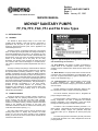
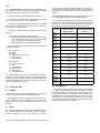
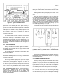
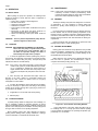
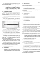
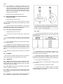
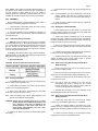
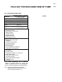
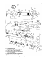
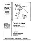
TABLE OF CONTENTS
Page
1-1. INTRODUCTION .................................................1
1-2. GENERAL.........................................................1
1-3. NAMEPLATE DATA .........................................1
1-4. Pump Rotation ...............................................1
1-5. Model Number ...............................................1
1-6. Frame Designation ........................................1
1-7. Type Designation...........................................2
1-8. Trim Code ......................................................2
2-1. INSTALLATION ..................................................2
2-2. GENERAL.........................................................2
2-3. PIPING..............................................................2
2-4. Suction Piping................................................2
2-5. Discharge Piping............................................2
2-6. FOUNDATION ..................................................2
2-7. SHAFT ALIGNMENT ........................................3
2-8. On Coupling Connected Units .......................3
2-9. On Belt Drive Units ........................................3
2-10. WATER FLUSH OF PACKING.......................3
2-11. SHAFT BEARING...........................................3
2-12. CLEAN-IN-PLACE (CIP) OPTION..................3
3-1. OPERATION .......................................................4
3-2. INITIAL CHECK ................................................4
3-3. STARTUP .........................................................4
3-4. PACKING LEAKAGE........................................4
4-1. MAINTENANCE ..................................................4
4-2. GENERAL.........................................................4
4-3. PACKING ADJUSTMENT ................................4
4-4. PACKING REPLACEMENT .............................5
4-5. DISASSEMBLY ................................................5
4-6. Disconnect Pump...........................................5
4-7. Packing Removal...........................................5
4-8. Stator Removal ..............................................5
4-9. Rotor and/or Drive Train Removal.................5
Page
4-10. Rotor, Connecting Rod and
Intermediate Drive Shaft Disassembly ......... 6
4-11. Drive shaft and Bearings Removal ......... 6
4-12. CLEANING .................................................. 6
4-13. INSPECTION .............................................. 6
4-14. Bearings .................................................. 6
4-15.DriveShaft................................................. 6
4-16. Seals ....................................................... 6
4-17. Packing.................................................... 6
4-18. Rotor........................................................ 6
4-19. Stator
4-20. ASSEMBLY ................................................. 7
4-21. Lubrication During Assembly .................. 7
4-22. Packing Installation ................................. 7
4-23. Bearing-Drive Shaft Assembly ................ 7
4-24. Rotor, Connecting Rod and
Intermediate Drive Shaft Assembly......... 7
4-25. Rotor, Connecting Rod and
Intermediate Drive Shaft Installation ....... 7
4-26. Stator Installation .................................... 8
4-27. Reconnect Pump..................................... 8
4-28. Mechanical Seal Installation.................... 8
4-29. STORAGE................................................... 8
4-30. Short-Term Storage ................................ 8
4-31. Long-Term Storage ................................. 8
4-32. VARIATIONS OF STANDARD PARTS ...... 8
4-33. Trim Code................................................ 8
4-34. Packing.................................................... 9
4-35. Rotors...................................................... 9
4-36. Intermediate Drive Shaft ......................... 9
4-37. STANDARD HARDWARE ........................ 10
4-38. PARTS LIST...........................................10, 12
4-39. TROUBLESHOOTING CHART................. 11
Section:
MOYNO SANITARY PUMPS
Page: 1
Date: January 30, 1990
SERVICE MANUAL
MOYNO® SANITARY PUMPS
FF, FG, FFC, FGC, FFJ and FGJ Frame Types
1-1. INTRODUCTION
1-2. GENERAL
The Robbins & Myers Moyno Pump is one of the most
versatile pumps available, It has been proven in thousands of
applications over the past 50 years and is backed by the
experience gained during these years, both in application and
manufacturing know-how.
The Moyno Pump is a progressing cavity pump. The pumping
action is created by the single helical rotor rolling eccentrically in
the double threaded helix of the stator. In its revolution, the rotor
forms in conjunction with the stator a series of sealed cavities 180
degrees apart. As the rotor turns, the cavities progress from the
suction to the discharge end of the pump. As one cavity
diminishes, the opposing cavity increases at exactly the same
rate. Thus the sum of the two discharges is a constant volume.
The result is a pulsation-free positive displacement flow with no
valves.
The Moyno Sanitary Pump design, combined with the effective
progressing cavity pumping principle, enables the food, chemical
and pharmaceutical processing industries to comply with 3A
sanitation requirements and FDA, USDA and BISSC sanitation
standards (mechanical seal required; pumps with packing do not
meet 3A approval). The standard sanitary flanged and gasketed
clamp-style connections on the suction and discharge ports and
the open throat design permit the Moyno Sanitary Pump to pump
fluids with diverse handling characteristics. Easy disassembly of
pumping elements, accomplished in a few short minutes,
provides for quick cleanup between “lot” processing, line
changeovers and shutdowns. An optional clean-in-place (CIP)
capability enables the Moyno Sanitary Pump to be cleaned
without being disassembled.
1-3. NAMEPLATE DATA
The Moyno Sanitary Pump is modular in design, consisting of
two separate units: the pumping elements (rotor, stator and
suction housing) and the drive end (drive shaft, bearings,
housing, connecting rod and other parts). The pump nameplate,
located on the bearing housing, contains important information
relating to the operation and servicing of the pump. This
information includes the direction of rotation arrow and the pump
model and serial numbers (see Fig. 1-1).
The pump model number must be used for reference when
ordering spare parts. To simplify this procedure, the model
number for your pump has been recorded on the nameplate
drawing on the front cover of this manual. Please carefully file this
manual for further reference.
Figure 1-1. Typical nameplate showing rotation arrow, model
and manufacturing serial numbers.
1-4. Pump Rotation. The direction of rotation is indicated by a
rotation arrow on the nameplate. Normal rotation of Moyno
Sanitary Pumps is clockwise when viewed from the driven end of
the pump.
1-5. Model Number. The pump model number consists of three
component parts: frame designations, type designations and a
trim code. A typical model number might be 1FG3 SSE FAA, as
shown on the nameplate in Fig. 1-1.
1-6. Frame Designation. The frame designation consists of four
to seven characters (e.g., 1FG3) sequenced to provide
identification of the number of stages, type of frame and element
size of the pump.
The first character in the frame designation, always a number, indicates the number of stages of the pumping elements.
The second character, always the letter F, designates the
pump as being the sanitary type.
The third character, either the letter F or G, designates the
bearing configuration. The letter F designates the standard
bearings configuration, and G designates a frame size larger
bearings and bearing housing to handle increased loads.
The letter F or G is sometimes followed by the letter J or C.
When present, J designates the open-throat hopper instead of
the standard sanitary flanged and gasketed clamp-style
connection suction port. C designates the clean-in-place (CIP)
option.
The fourth through seventh characters (as used), all numeric
or numeric with the letter H as a suffix, designate the size of the
pumping elements.
Page 2
1-7. Type DesIgnatIon. Following the frame designation is the
type designation, a series of three letters describing the materials
from which the pump is constructed (e.g., 1FG3-SSE).
The first letter identifies the material of the body casting.
The second letter identifies the material used in the drive
shaft, connecting rod, rotor and other wettable parts.
The third letter identifies the material of the stator. It identifies
only the stator material and not the tube in which the stator is
placed; the tube is stainless steel.
A typical type designation such as SSE would result in the
following:
S = Stainless steel, type #304 suction housing
S = Stainless steel, type #316 internals including drive shaft,
pins, connecting rod, rotor, and other minor metallic
parts in contact with the material being pumped
E = Nitrile rubber stator (70 durometer; food grade)
The following letters identify the actual materials that are used
in standard construction:
• FDA food grade
B— EPDM
E— Nitrile
S — Stainless steel (316 or 304)
T — Teflon* (PTFE)
V — Fluoroelastomer
• Non-food grade
J — 17-4 stainless steel
Q— Nitrile
F — Fluoroelastomer
A — Natural rubber
Z — Nitrile (white)
G — 416 stainless steel
1-8. Trim Code. Also included in the nameplate is the threecharacter trim code designation. The first letter identifies sealing
methods, the second character identifies internal variations and
the third letter identifies rotor variations. Consult Section 4-33 for
a further explanation of trim code.
2-1. INSTALLATION
2-2. GENERAL
Moyno Pumps are lubricated and tested at the factory prior to
shipment and require minimum pre-startup maintenance.
Accessibility to the pump and adequate clearance should be a
prime consideration in any installation. Enough space should
surround the unit so that pump maintenance can be carried out
with ease.
2-3. PIPING
2-4. Suction piping should be as short as possible. Normally,
the suction line should be the same size as the pump suction.
However, conditions such as high viscosity or required
* Teflon is a registered trademark of E.I. duPont de Nemours & Co. Inc.
minimum flow velocities may dictate otherwise. Long-sweep 90degree elbows or 45-degree elbows should be used instead of
the standard elbow. Suction piping loops which trap air should be
avoided.
2-5. Discharge piping diameter should generally be as large as
the pump port unless fluids conditions indicate otherwise.
An easily removable section of piping one to two times longer
than the stator (see the following chart) should be mated to the
discharge port. This will allow the rotor and stator to be removed
without having to completely remove the pump from the base.
Pump
Suggested Discharge
Piping Lengths
and/or Clearance
1FG3
1FGJ3
2FG3
2FGJ3
3FG3
3FGJ3
1FF4
1FFJ4
2FG4
2FGJ4
4FG4
4FGJ4
1FF6
1FFJ6
2FG6
2FGJ6
3FG6
3FGJ6
1FF8
1 FFJ8
2FG8
2FGJ8
3FG8
3FGJ8
1FF1O
1FFJ1 0
1FF10H
1FFJ1OH
1FF66
1FFJ66
Minimum Discharge
Piping Lengths and/or
Clearance
8 in.
2 in.
13 in.
2 in.
19 in.
2 in.
11 in.
2 in.
18 in.
2 in.
32 in.
2 in.
16 in.
2 in.
27 in.
2 in.
38 in.
2 in.
20 in.
2 in.
33 in.
2 in.
45 in.
2 in.
25 in.
2 in.
25 in.
2 in.
31 in.
2 in.
2-6. FOUNDATION
For maximum pump-driver life, each unit should be mounted
on a strong, fabricated-steel base plate which can be ordered
from Robbins & Myers. The base plate should be mounted on a
concrete foundation built on a solid base. The foundation should
be approximately 4” longer and wider than the base on which it is
built (see Fig. 2-1) and should be an overall size of 4” to 8” larger
than the base plate once it is mounted. Anchor bolts for the base
plate should be located in the foundation.
Page 3
2-10.
WATER FLUSH OF PACKING
The packing may be either grease lubricated through a grease
fitting in the packing retainer or have plumbing connected to the
housing to allow a water flush.
When the material being pumped is abrasive in nature, it may
be advantageous to flush the packing to prevent excessive shaft
wear.
Figure 2-1. Typical Foundation Example
Check the base plate surface with a carpenter’s level and
place shims under the base plate at the places necessary to
make it level. Then check the pump driver shafts and the pump
ports to ensure that they are level. Complete base mounted units
supplied by Robbins & Myers, including pump driver, are leveled
with respect to the base at the factory. Shifting may occur during
shipment. The pump and driver should be realigned. Care should
be exercised to ensure that all components are level and
mounted in a direct line.
Clean water can be injected through a 1/8” NPT tapped hole
that normally houses the grease fitting for lubricating the packing.
The water can be permitted to leak axially along the shaft and be
removed from the second tapped hole in the packing retainer.
The discharge from the packing retainer should be throttled
slightly to maintain a 10 to 15 psi higher pressure in the packing
retainer than is present in the suction housing (see Fig. 2-2). Flow
rate should be approximately 1/2 to 2 gpm.
If mechanical seals are to be used on the unit, consult the seal
manufacturer’s instructions for seal flush requirements.
For maximum rigidity and lower noise levels, the base plate
should be grouted to the foundation after the anchor bolts have
been evenly tightened. A good grade of nonshrink grout is
recommended. The spaces between the base plate and the
foundation around the shims and inside the bushings for the
anchor bolts should also be filled with grout. Allow the grout to dry
according to manufacturer’s instructions. Then fully tighten the
anchor bolts.
2-7. SHAFT ALIGNMENT
Although the base mounted units supplied by Robbins &
Myers are leveled with respect to the base before shipping, most
of the larger pump and driver units are shipped with the flexible
coupling disconnected.
Figure 2-2. Typical water flush arrangement includes
strainer valve (1), sight flow indicator (2), pressure
regulating valve (3), solenoid valve (4), pressure gauge
(5) and needle valve (6).
After the base has been bolted down to the foundation, check
the following conditions:
2-11. SHAFT BEARING
2-8. On coupling connected units, be sure that the pump and
driver shafts are realigned before the coupling is connected. Care
should be exercised to ensure that all components are level and
mounted in a direct line.
Check the gap between coupling halves (refer to the coupling
manufacturer’s recommendations). Adjustment can usually be
accomplished by loosening the mounting bolts on either the pump
or driver and moving the loosened component into alignment with
the fixed component. On couplings with equal diameter hubs, it
may be helpful to lay a straightedge axially across the coupling
halves to check the alignment.
2-9.
On belt drive units, check to ensure that sheaves or
sprockets are in alignment. Check belts for proper tension.
Tension requirements will vary with the type of belt, center
distances and belt speeds. Consult the belt manufacturer for
specific recommendations.
The bearings are lubricated at the factory and will only need to
be relubricated when the shaft/bearing assembly is completely
removed from the pump.
2-12. CLEAN-IN-PLACE (CIP) OPTION
The Moyno Sanitary Pump can be customized with a suction
housing and reducer equipped for clean-in-place (CIP)
operations. On a pump with the CIP option, additional ports in the
suction housing and reducer permit a CIP bypass hookup. This
bypass allows an extremely high rate of water to be supplied to
the pump to create a turbulent condition which cleans pump parts
such as flexible joints. Excess water passes through the bypass.
Two close-coupled valves should be installed in the bypass
line, one at each end of the line, to close off the bypass during
normal pumping operations. One of the valves should be a threeway valve so that one port is open to the atmosphere for drainage
when the valves are closed.
Page 4
4-1. MAINTENANCE
3-1. OPERATION
3-2. INITIAL CHECK
Before putting the pump into operation, the following items
should be checked to ensure that each piece of equipment is
installed correctly:
— Pump, driver, coupling or sheave alignment
— Electrical connections
— Gauges and other instruments
— Water flush connection
— Pump rotation (normal rotation is indicated on the pump
drive end)
— Belt tension on belt driven units (there should be no
appreciable deflection when first starting up)
— Suction and discharge valves (both valves should be
open)
CAUTION: This is a positive displacement pump. Do not
operate it against a closed valve.
3-3. STARTUP
CAUTION: DRY OPERATION IS HARMFUL TO THE PUMP!
Never allow the pump to operate without liquid
as dry operation will cause premature wear of
the stator and possible damage. The stator Is
lubricated by the liquid which is pumped.
1. In suction lift applications: Before operating the pump for
the first time, fill it with liquid. If the liquid to be pumped is highly
viscous, dilute it before filling the pump. The liquid fill-up will
lubricate the stator for the initial startup.
Note: In this section, the first reference to each pump part will be
followed by a number or a letter in parentheses (). These
numbers and letters identify the pump parts and hardware
items in the foldout exploded view (Fig. 4-4).
4-2. GENERAL
The Moyno Sanitary Pump has been designed for a minimum
of maintenance. It is only necessary to routinely adjust and
lubricate the packing. Shaft bearings do not require periodic
lubrication.
It is good practice to periodically touch the bearing housing to
become familiar with the normal operating temperature of the
bearings. If there is a sudden, rapid rise in operating temperature,
remove the intermediate drive shaft and shaft bearings from the
bearing housing and either clean and relubricate the bearings or
replace them.
Inspect and either clean and relubricate or replace the shaft
bearings every 8,000 to 10,000 operating hours.
4.3. PACKING ADJUSTMENT
Packing gland nuts should be evenly adjusted so they are little
more than fingertight. Overtightening of the packing gland may
result in premature packing failure and possible damage to the
intermediate drive shaft and gland.
When packing is new, frequent minor adjustments during the
first few hours of operation are recommended in order to
compress and seat the packing (see Fig. 4-1).
Note: If the pump is shut down temporarily, enough liquid will
remain in the system to provide lubrication upon restarting. it is advisable to maintain the suction piping at a
higher elevation than the center line of the pump in order
to contain some liquid in the pump at the time of the shutdown.
2. Once the pump has been filled with liquid, check the
direction of the pump rotation by momentarily starting and
stopping the drive. Check the rotation arrow on the pump
nameplate for correct rotation.
3. In suction lift applications: When water flush is not utilized,
it may be necessary to replace the zerk fitting at the packing
retainer (in the suction housing) with a pipe plug to prevent loss
of prime due to air leakage.
4. If applicable, turn on the seal water to the packing.
5. Start the pump.
3-4. PACKING LEAKAGE
A packed packing retainer is designed to control leakage, not
stop it completely. Leakage is generally necessary to reduce
friction and dissipate heat. The amount of leakage necessary will
depend on the fluid pumped, the installation, and the pump speed
and type. Refer to Section 4-3 for packing adjustment.
Moyno Sanitary Pumps have been designed for minimum
packing retainer leakage when properly maintained. If leakage
cannot be tolerated, a mechanical seal should be used.
Figure 4-1. Cross Section of Packing Retainer
1. Upon initial startup of the pump, adjust the gland nuts (A)
for a leakage rate of 1 to 2 drops per second until the packing
(14) has seated and adjusted to the operating temperature (approximately 10 to 15 minutes).
Page 5
2. If there is excessive leakage from the packing retainer (15)
after 15 minutes of operation, tighten the gland nuts until a
desired leakage rate is obtained.
CAUTION: Do not tighten until zero leakage is obtained.
Overtightening of the packing gland may result In
accelerated wear on the packing and damage to
the shaft. In those situations where no packing
leakage can be tolerated, consult your Moyno
authorized service representative.
4-6. DIsconnect Pump
1. Operate the pump (preferably with clean water) to ensure
that the rotor and stator are not dry.
2. Shut off the pump.
3. Close the suction and discharge valves.
4. If applicable, turn off the flush water to the packing (14) or
mechanical seal.
4-4. PACKING REPLACEMENT
5. Disconnect the power source.
When leakage can no longer be regulated by tightening the
gland nuts, remove and replace the packing. The entire pump
need not be disassembled to replace the packing. Briefly, replace
the packing as follows:
1. Remove the gland nuts (A) and packing gland (13) from the
packing retainer (15).
4-7. Packing Removal
1. Stop the pump.
2. Complete Section 4-6, steps 3 through 5.
3. Complete Section 4-4, steps 1 through 3.
2. Use a pair of packing extractors (Fig. 4-2) to remove the
first three packing rings (14), the lantern rings (19) and the last
three packing rings.
4-8. Stator Removal
1. Complete Section 4-6.
2. If applicable and necessary, remove the clean-in-place
(CIP) pipe and valves.
3. Remove the section of discharge pipe attached to the reducer (3).
4. Loosen the wing nut (26) and swing the eyebolt (27) free
from the stator clamp (4); then remove the stator clamp.
Figure 4-2. Packing Removal Tool
3. Inspect the surface of the intermediate drive shaft (7) for
excessive wear or grooves due to packing rub, If the shaft is
worn, or is badly scored or grooved, it should be replaced.
4. If the intermediate drive shaft is not worn, lubricate the six
new packing rings with a good grade of packing grease (see
Section 4-21).
5. Insert three rings of packing, the lantern ring halves (with
flat sides facing packing) and the remaining three packing rings
onto the shaft. Tamp each ring into the packing retainer with the
packing gland. Be sure to stagger the packing ring joints at 90degree increments (see Section 4-22).
5. Loosen the two clamp nut assemblies (32) sufficiently to
free the clamp studs (25); then remove the clamp studs.
6. Pull the reducer from the end of the stator (33) and pull the
stator from the rotor (34); then remove the O-rings (28) from the
stator.
Note: To assist with the removal of the stator on larger pumps,
slide the pull-out sleeve (30) over the end of the stator.
Align the threaded holes in the sleeve with the pilot holes
in the stator and insert the two pull-out rods (31). With the
rod tips seated in the pilot holes in the stator, grip the rods
to twist and pull the stator from the rotor.
7. Inspect the stator for wear (see Section 4-19).
All but one packing ring may fit into the packing retainer. As
the pump operates, the packing will compress and the last
packing ring can be added.
4-9. Rotor and/or Drive Train Removal
6. Position the packing gland on the gland studs (17) and
secure with the gland nuts. Tighten the nuts evenly but only tight
enough to seat packing and provide a good seal. Over-tightening
will cause failure of the packing and shaft by overheating.
Note: Skip step 2 and proceed with step 3 if the Sanitary Pump
is equipped with a mechanical seal.
7. Adjust the packing per Section 4-3.
2. Loosen the packing gland nuts (A) on the gland studs (17).
3. At the drive shaft (6) end of the pump, unseat the snap
ring (24) and slide the snap ring and pin retainer (18) toward the
pump driver.
4-5. DISASSEMBLY
Note: The following instructions cover one procedure
assembling all pump components. Major pump
nents can be disassembled in various ways since
installation location limitations will determine the
of component removal.
1. Complete Sections 4-6 and 4-8.
for discompospecific
method
4. Remove the pin (16) from the drive shaft, using a small
punch, if necessary.
5. Pull the rotor (34), connecting rod (5) and intermediate
drive shaft (7) as a unit from the housings.
Page 6
Note: If end clearance is not available to pull this unit in one
piece, disconnect the suction piping so that the suction
housing (2) and the packing retainer (15) can be removed
with the rotor/intermediate drive shaft assembly and then
separated. Note that the packing retainer must be rotated
before it can be removed so the zerk fitting will pass
through the groove provided.
6. Inspect the rotor for wear (see Section 4-18).
4-10. Rotor, Connecting Rod and Intermediate Drive
Shaft Disassembly
1. Complete Sections 4-6, 4-8 and 4-9.
2. Unseat the snap rings (24) at each end of the connecting
rod (5) and slide the snap rings and pin retainers (18) onto the
connecting rod.
3. Remove the pins (16) and separate the rotor (34) and
intermediate drive shaft (7) from the connecting rod. Remove the
snap rings and pin retainers from the connecting rod.
4-11. Drive Shaft and Bearings Removal
1. Complete Sections 4-6, 4-8 and 4-9.
2. Disconnect and remove the pump driver and the drive
coupling.
Figure 4-3. Measuring Rotor Dimension
4-18. Rotor
1. To check for excessive wear of the rotor (34), measure the
rotor crest-to-crest diameter (see Fig. 4-3) and compare it with
the following chart.
3.
Unbolt the bearing cover plate (11) from the bearing
housing (1) and remove the cover plate and thrust grease seal
(23).
4. Pull or press the bearings (8 and 9) and drive shaft (6)
from the bearing housing.
5. Straighten the tab of the lockwasher (21) and remove the
bearing locknut (20), lockwasher, radial bail bearing (8), spacer
(10) and thrust ball bearing (9) from the drive shaft, It will be
necessary to use a hydraulic press to remove bearings from drive
shaft.
6.
Remove the radial grease seal (22) from the bearing
housing.
4-12. CLEANING
Clean all parts in a suitable cleaning solvent, being careful to
observe all safety precautions regarding the use of solvent.
4-13. INSPECTION
4-14. Bearings. After cleaning, rotate the bearings (8 and 9)
slowly, feeling for smoothness and even action. Check for cracks,
galling, pitting, burrs, etc. Replace bearings if there is any doubt
concerning complete serviceability.
4-15. Drive Shaft. Inspect the drive shaft (6) for scoring, burrs,
cracks, etc. Replace as necessary.
4-16. Seals. It is good practice to always replace grease seals
(22 and 23) whenever the drive shaft (6) and the bearings (8 and
9) are removed.
4-17. Packing. It is good practice to always replace packing
(14) whenever the pump bearing housing (1) is disassembled.
* These dimensions are applicable for FAA and SAA trim codes
only.
2. If the measured crest-to-crest diameter is within 0.010* of
the standard value and is free of deep nicks, gouges or other
surface defects, the rotor is reusable.
3. Rotors with crest-to-crest values 0.011” to 0.050” under
the standard values should be replaced. These rotors can be
renewed by chrome plating to standard dimensions provided that:
a. the pin holes are not excessively worn.
b. the rotor surface is not cracked, pitted or deeply grooved
(1/32” or more).
c. the base metal surface is not pitted or corroded.
4. Rotors may be sent to Robbins & Myers or any other
competent plating shop. Rotors should be stripped and replated
to standard dimensions, then buffed.
Page 7
4-19. Stator. A worn stator may appear pitted and gouged, or it
may appear smooth similar to when it was new. Performance is
the best measure of rotor-to-stator fit. If you are unable to
measure performance adequately, suspected stator wear can be
evaluated by a Robbins & Myers sales or factory representative.
c. Install the final three packing rings, firmly pushing each ring
into place.
4-20. ASSEMBLY
Note: On initial assembly, one ring of packing may not fit into the
packing retainer. This final ring of packing should be
installed after the pump has been started and packing is
seated.
Moyno Sanitary Pumps are reassembled in reverse order of
dismantling. The following suggestions are offered:
3. Install the packing gland and gland nuts (A). Tighten the
nuts finger tight at this time.
1. While the pump is dismantled, check all O-rings, packing
and snap rings. Replace all worn parts.
4.23. Bearing-Drive Shaft Assembly
2. During the assembly process, cleanliness is important. To
avoid premature failure, all components must be handled with
care and kept clean.
4-21. Lubrication During Assembly
1. Bearings. Pack the bearings (8 and 9) prior to assembly
into the bearing housing (1). After pressing bearings and spacer
(10) on drive shaft (6) and tightening the bearing lock nut (20), fill
the area between the two bearings with lubricant. Lubricant
should be packed around all of the balls and should completely
cover the faces of the bearing races.
2. Packing. Lubricate the packing rings (14) during assembly.
Additional grease can be added after assembly through the zerk
fitting (G) in the packing retainer (15).
3. Approved lubricants:
CAUTION: Do not mix different brands of lubricants.
1. Press bearings (8 and 9) with spacer (10) onto the drive
shaft (6), applying pressure to the inner races only. Make sure
the bearings are seated fully on the shaft.
2. Install a new bearing Iockwasher (21) on the shaft and
bearing locknut (20). Tighten the locknut securely and bend the
tab of the Iockwasher down into the wrenching slot of the bearing
locknut to prevent loosening of the locknut.
3. Install a new radial grease seal (22) in the bearing housing
(1) and a new thrust grease seal (23) in the bearing cover plate
(11).
4. Carefully insert the bearing shaft assembly into the bearing
housing so as not to damage the radial grease seal.
5. Install the bearing cover plate with the thrust grease seal.
Tighten all bearing cover screws (B)(C) evenly to prevent
damage to the cover plate and grease seal.
4-24. Rotor, Connecting Rod and Intermediate Drive
Shaft Assembly
1. Place one snap ring (24) and one pin retainer (18) over
one end of the connecting rod (5).
2. Insert the connecting rod end into the bore of the rotor (34),
aligning the pin holes and inserting a lightly lubricated pin (16).
4-22. Packing Installation
1. The standard packing set (14) consists of six packing rings
and two Teflon lantern ring halves (19).
3. Slide the pin retainer over the pin and seat the snap ring in
the groove on the rotor.
2. Install packing and lantern ring halves into the packing
retainer (15) in the following sequence:
Note: Two sets of holes are provided in the rotor and the
intermediate drive shaft (7). Should one set of holes
become elongated by wear, rotate the parts to align the
connecting rod hole with the unused holes.
a. Wipe a film of lubricant on each packing ring and install
three rings. Push each ring firmly in place.
4. Assemble the connecting rod and rotor assembly to the
intermediate drive shaft in the same manner.
Note: Install the packing rings with the splits staggered at 90
degrees to the adjacent ring of packing.
4-25. Rotor, Connecting Rod and Intermediate Drive
Shaft Installation
CAUTION: Always use the packIng gland (13) or a proper
packing tamper tool to install the packing. Do not
use a pointed or sharp tool, as damage to the
packing material or drive shaft could result. To
assure proper shaft lubrication, never use a onepiece spiral wrap packing.
1. Position the O-ring (29) in the groove on the packing
retainer (15), and install the gland studs (17), if removed.
b. Install the two lantern ring halves with the flat sides against
the packing.
2. Position the packing retainer in the support ring of the
bearing housing (1), sliding the packing gland (13) onto the gland
studs. Rotate the packing retainer so that the zerk fitting (G) is on
top.
3. Position the suction housing (2) on the bearing housing,
engaging the O-ring end of the packing retainer.
Page 8
4. Insert the rotor-rod-shaft assembly through the suction
housing and packing retainer, seating the end of the intermediate
drive shaft (7) into the drive shaft (6). Rotate the shafts to align
the pin holes and insert the pin (16).
5. Slide the pin retainer (18) in place on the drive shaft and
seat the snap ring (24) in the groove provided.
4. Install the stationary component (carbon and O-ring) of
mechanical seal (14a) in seat of seal retainer.
5. Slide the rotating component (spring and ceramic) onto the
intermediate drive shaft (7a) so that the tab of the spring fits into
the slot in the intermediate drive shaft. It may be necessary to
wipe a small amount of lubricant around inside diameter of
rotating component.
4-26. Stator Installation
1. Install the stator O-rings (28) on the ends of the stator (33).
6. Position the suction housing (2) on the bearing housing,
engaging the O-ring end of the seal retainer.
2. Coat the inside of the stator (33) and rotor (34) with
lubricant compatible both with the stator material and the material
to be pumped.
7. Complete Section 4-25, steps 4 and 5, to reinstall the rotor,
connecting rod and intermediate drive shaft. Care should be
taken not to damage carbon stationary component of seal.
3. Thread the stator onto the rotor. Align the suction port of
the suction housing (2) with the intake piping and seat the stator
into the suction housing.
4-29. STORAGE
4. Position the reducer (3) on the end of the stator.
Note: If the pump is equipped with a pull-out sleeve (30) and
pull-out rods (31), they may be used to assist in installing
the stator into the rotor. Install the sleeve and rods as
noted in Disassembly Section 4-8. When the stator is
seated on the rotor, remove the rods and sleeve before
installing the reducer.
5. Position the clamp studs (25) with the loosened clamp nut
assemblies (32) and the eyebolt (27) in the slots of the reducer,
stator support (12) and the bearing housing (1), aligning the
eyebolt between the yokes of the stator support. Tighten the
clamp nut assemblies sufficiently to seat and seal all O-ring
joints.
6. Position the stator clamp (4) over the stator and stator
support, hooking one side on the clamp stud and securing the
other side with the eyebolt and wing nut (26).
7. Install the section of discharge pipe that attaches to the
reducer.
4-27. Reconnect Pump
1. If applicable, close the clean-in-place (CIP) valves.
2. If applicable, turn on the flush water to the packing or
mechanical seal.
3. Open the suction and discharge valves.
4. Reconnect the power source.
4-28. Mechanical Seal Installation
1. Complete Sections 4-20, 4-21,4-23 and 4-24.
2. Position the O-ring (29) in the groove on the seal retainer
(15a).
3. Position the seal retainer in the support ring on the bearing
housing (1).
4-30. Short-Term Storage. Storage of six months or less will
not damage the sanitary type pump. However, to ensure the best
possible protection, the following is advised:
1. Cover the pump with some type of protective covering. Do
not allow moisture to collect around the pump.
2. Disassemble the pumping elements and thoroughly clean
all components. Dry the components completely and reassemble.
3. Loosen the packing gland and inject a liberal amount of
lubricant into the packing retainer. Tighten the packing gland only
hand tight. When water flush systems are used, do not use
grease. A small amount of light oil is recommended, instead.
4. See drive manufacturer’s instructions for motor and/or drive
storage.
5. See OPERATION Sections 3-1 through 3-4 before startup.
Be sure all lubricants are in good condition.
4-31. Long-Term Storage. If the pump is to be in storage for
more than six months, perform the above short-term storage
procedures plus the following:
1. Periodically, rotate the pump manually a few revolutions to
avoid a “set” condition of the rotor in the stator elastomer. This
will prevent hard starting and excessive torque requirements
when the pump is again put in operation.
2. Apply rust inhibitor to all unpainted cast iron surfaces.
3. If applicable, remove drive belts.
4-32. VARIATIONS OF STANDARD PARTS
4-33. Trim Code. Also included on the nameplate is the threepart trim code which is used to identify pump construction. Each
character of the trim code identifies a specific aspect of pump
construction. The first character identifies sealing variations; the
second, internal variations; the third, rotor variations.
Page 9
• Sealing Variations:
D — Double mechanical seal. Optional.
F — Braided Teflon food grade packing
(white). Standard on all sanitary pumps.
S — Single mechanical seal. Optional.
X — Special to application.
• Internal Variations:
A — Standard plated shaft
B — Non-plated shaft
E — Extension tube with extended auger
G — Ceramic coating
X — Special to application
• Rotor Variations:
A — Standard size with chrome plating
B — Non-plated (no plating)
C — Standard undersize
E — Standard oversize
G — Ceramic coating
X — Special to application
The trim code FAA represents a pump with standard features.
Deviations from standard are indicated by substituting the
appropriate character from the list above. For example, the trim
code SAA identifies a pump with a single mechanical seal. The
trim code FBE identifies a pump with non-plated shaft and an
oversized rotor.
When two or more characters are combined to identify a
variation, the three parts of the trim code are separated by
dashes. For example, the trim code F-A-EB identifies a pump
with a non-plated, oversized rotor.
4-34. Packing on all Moyno Sanitary Pump consists of six solid
braided Teflon packing rings and two Teflon lantern rings, with
food grade lubricant or water flush (a pump with packing does not
meet 3A approval). Single or double mechanical seals with or
without water flush are available. Consult your Moyno
representative.
4-35. Rotors identified on parts listing are standard size with
hard chrome plated surface. Other variations of rotor size and
finish may be ordered by selecting the standard rotor part number
and changing the last digit of the rotor number as follows:
1 = Standard size, chrome plated
2 = Standard size, nonplated
3 = Undersize, chrome plated
4 = Undersize, nonplated
Do not change rotor sizes without consulting your Moyno
sales office. These variations are used for certain specialized
pumping conditions only.
4-36. Intermediate drive shaft shown has hard chrome plating
on the packing wear area. If a nonplated intermediate drive shaft
is required, select the standard part number and change the last
digit to the next higher number (e.g., F04281 to F04282).
Page 10
4.37 STANDARD HARDWARE
REF. DESCRIPTION
A
B
C
D
E
F
G
Packing Gland Nut
Brg. Cover Screw (Hex Head)
Brg. Cover Screw (Hex Head)
Brg. Cover Lock Washer
Brg. Cover Lock Washer
Drive Shaft Key
Zerk Fitting
AMT.
FG3,FF4
FGJ3,FFJ4
FG4,FF6
FGJ4,FFJ6
FG6,FF8
FGJ6,FFJ8
FG8,FF10,FF10H,
FF66 FGJ8,FFJ10,
FFJ10H,FFJ66
2
4
5
4
5
1
2
1/4-20
5/16-18x3/4
—
5/16
—
1/4x1/4x2 1/4
1/8 NPT
1/4-20
318-16x1 ¼
—
3/8
—
1/4x1/4x2 1/4
1/8 NPT
1/2-13
½-13x1 1/2
—
1/2
—
3/8x3/8x2 1/8
1/8 NPT
1/2-13
—
1/2-13x1 1/2
—
1/2
1/2x1/2x3 3/4
1/8 NPT
4.38 PARTS LIST
REF.
NO. DESCRIPTION
1
Bearing Housing
2
Suction Housing
FG
FGJ
FF
FFJ
2a
3
3a
4
5
6
7
7a
8
9
10
11
12
13
14
14a
15
15a
16
17
Suction Housing — CIP Option
FGC
FFC
Reducer
FGJ/FG
FFJ/FF
Reducer — CIP Option
FGC
FFC
Stator Clamp
FG/FGJ
FF/FFJ
Connecting Rod
FG/FF
FGJ/FFJ
Drive Shaft
Intermediate Drive Shaft
Intermediate Drive Shaft Mechanical Seal
Ball Bearing Radial
Ball Bearing Thrust
Bearing Spacer
Bearing Cover Plate
Stator Support
FG/FGJ
FF/FFJ
Packing Gland
Packing
Mechanical Seal (FAQ) Single
Seal-Nitrite
Packing Retainer
Seal Retainer
Rotor Pin
Gland Stud
FG3/FF4
FGJ3/FFJ4
PART NO.
F04011
FG4/FF6
FGJ4/FFJ6
PART NO.
F06011
FG6/FF8
FGJ6/FFJ8
PART NO.
F08011
FG8/FF10
FGJ8/FFJ10
PART NO.
F10011
FF10H
FFJ10H
PART NO.
F10011
FF66
FFJ66
PART NO.
F10011
F04121
F04022
F04123
F04024
F06121
F06022
F06121
F06022
F08121
F08022
F08123
F08024
F10121
F10022
F10123
F10024
—
—
F10123
F10024
—
—
F10123
F10024
F04126
F04127
F06126
F06126
F08126
F08127
F10126
F10127
F10126
F10127
F10126
F10127
F04191
F04192
F06191
F06191
F08191
F08192
F10191
F10192
—
F10192
—
F10192
F04193
F04194
F06192
F06192
F08193
F08194
F10193
F10194
F10193
F10194
F10193
F10194
F04201
F04202
F06201
F06201
F08201
F08202
F10201
F10202
—
F10202
—
F10202
F0425S
F0425J
F04261
F04281
F04283
F0625S
F0625J
F06261
F06281
F06283
F0825S
F0825J
F08261
F08281
F08283
F1025S
F1025J
F10261
F10281
F10283
F1025S
F1025J
F10261
F01281
F10283
F1025S
F1025J
F10261
F01281
F10283
A03291
A04301
F04331
F04341
A06291
F06301
F06331
F06341
F08291
F08301
F08331
F08341
A10291
F10301
F1033l
F10341
A10291
F10301
F10331
F10341
A10291
F10301
F10331
F10341
F04381
F04382
F0441S
F04425
F0448E
F06381
F06381
F0641S
F06425
F0648E
F08381
F08382
F0841S
F08425
F0848E
F10381
F10382
F1041S
F10425
F1048E
—
F10382
F1041S
F10425
F1048E
—
F10382
F1041S
F10425
F1048E
F04431
F04432
F0445S
F04471
F06431
F06432
F0645S
F04471
F08431
F08432
F0845S
F08471
F10431
F10432
F1045S
F08471
F10431
F10432
F1045S
F08471
F10431
F10432
F1045S
F08471
Page 11
FOLD OUT FOR EXPLODED VIEW OF PUMP
4-39. TROUBLESHOOTING CHART
SYMPTOMS
1
POSSIBLE CAUSE OF TROUBLE
(Each Number is Defined
In the List Below)
Pump fails to discharge: 1, 2, 3, 4, 5, 6, 8, 9, 16
Pump is noisy:
6,10,11,17,18,19
Pump wears rapidly:
11, 12, 13,20,24
Pump not up to capacity: 3,5,6, 7, 9, 16,21,22
Pump starts, then loses
suction:
1,2,6,7,10
Pump takes excessive
power:
14, 15, 17, 20, 23
Suction Troubles:
1. Not properly primed
2. Suction pipe not submerged
3. Strainer clogged
4. Leaking foot valve
5. Suction lift too high
6. Air leaks in suction
7. Suction pipe too small
System Problems:
8. Wrong direction of rotation
9. Low speed
10. Insufficient liquid supply
11. Excessive pressure
12. Grit or dirt in liquid
13. Pump runs dry
14. Viscosity higher than specified
15. Obstruction in discharge line
Mechanical Troubles:
16. Pump worn
17. Bent drive shaft
18. Coupling out of balance or alignment
19. Relief valve chatter
20. Pipe strain on pump casing
21. Air leak at packing
22. Relief valve improperly seated
23. Packing too tight
24. Corrosion
1
From PUMP HANDBOOK, Igor J. Karassik,
William C. Krutzsch, Warren H. Fraser, and
Joseph P. Messina, editors, © 1976 by McGrawHill, Inc. Used with permission from the publisher.
Note: If further troubleshooting procedural
information is needed, contact Technical
Service at Robbins & Myers, Inc.
NOTES
V
Page 12
PARTS LIST (CONT.)
REF.
NO.
18
19
20
21
22
23
24
25
26
27
28
29
30
31
32
33
34
DESCRIPTION
Pin Retainer
Lantern Ring
Bearing Locknut
Bearing Lockwasher
Radial Grease Seal
Thrust Grease Seal
Snap Ring
Clamp Stud
1FG/FGJ3
2FG/FGJ3
3FG/FGJ3
1FF/FFJ4
2FG/FGJ4
4FG/FGJ4
1FF/FFJ6
1FF/FFJ8
2FG/FGJ6
3FG/FGJ6
2FG/FGJ8
3FG/FGJ8
1FF/FFJ10
1FF/FFJ66
Wing Nut
Eye Bolt
Stator O-ring
FG
FF
O-ring
Pull-out Sleeve
FF
FG
Pull-out Rod
FF
PG
Clamp Nut Assembly
Stator
1FG/FGJ: SSB,SSV,
SSG,SSE,SSR,SST,SSZ
2FG/FGJ: SSB,SSV,
SSG,SSE,SSR,SST,SSZ
3FG/FGJ: SSB,SSV,
SSG,SSE,SSR,SST,SSZ
4FG/FGJ:
SSB,SSV,SSE,SSR,SSZ
1 FF/FFJ: SSB,SSV,
SSG,SSE,SSR,SST,SSZ
Rotor
1 FG/FGJ†
1FF/FFJ†
2FG/FGJ†
3FG/FGJ†
4FG/FGJ†
FG3/FF4
FGJ3/FFJ4
PART NO.
F04501
F04571
A04581
A04591
A02611
F04621
F04661
FG4/FF6
FGJ4/FFJ6
PART NO.
F06501
F06571
F06581
F06591
F06611
F06621
F06661
FG6/FF8
FGJ6/FFJ8
PART NO.
F08501
F08571
F08581
F08591
F08611
F08621
F08661
FG8/FF10
FGJ8/FFJ10
PART NO.
F10501
F10571
A10581
A10591
A10611
F10621
F10661
FF10H
FFJ10H
PART NO.
F10501
F10571
A10581
A10591
A10611
F10621
F10661
FF66
FFJ66
PART NO.
F10501
F10571
A10581
A10591
F10611
F10621
F10661
F04131
F04132
F04133
F04134
—
—
—
—
—
—
—
—
—
—
F04741
F04801
—
—
—
—
F06131
F06132
F06133
—
—
—
—
—
—
—
F08741
F06801
—
—
—
—
—
—
—
F08131
F08132
F08133
—
—
—
—
F08741
F08801
—
—
—
—
—
—
—
—
—
—
F10131
F10132
F10133
—
F10741
F10801
—
—
—
—
—
—
—
—
—
—
—
—
F10133
—
F10741
F10801
—
—
—
—
—
—
—
—
—
—
—
—
—
F66131
F10741
F10801
F04111
F04112
F04111
F06111
F06111
F06111
F08111
F08113
F08113
F08113
F10111
F10112
—
F10111
F10112
—
F10111
F10112
—
—
F06391
F06391
F08392
F06391
F10391
F08392
F10391
—
F10391
—
—
—
F04141
F06401
F06401
F06141
F06401
F06401
F08141
F10401
F06401
F10141
F10401
—
F10141
F10401
—
F10141
F5l03*
—
—
—
—
—
F5203*
F5204
F5206
F5208*
—
—
F5303
—
F5306*
F5308*
—
—
—
F5404*
—
—
—
—
F5104
F5106*
F5108
F5110*
F5111*
F5166*
F8103†
F8104†
F8203†
F8303†
—
—
F8106†
F8204†
—
F8404†
—
F8110†
F8208†
F8308†
—
—
F8111†
—
—
—
—
F8166†
—
—
—
—
F8108†
F8206†
F8306†
—
*Add the third letter of the type designation to complete the part number (e.g., for a type SSE pump, add E to the basic number of the stator).
† See page 9 for variations.
Page 13
Figure 4-4. Pump Exploded View
Double The Length Of Your
Moyno Pump Warranty For FREE!
For your free pump warranty extension, choose from one of the three options below:
1. Go to www.moyno.com and fill out the registration form online
2. Mail this form by placing it in an envelope and sending it to: Moyno, Inc.
Attn: Tish Wilson
P. O. Box 960
3. Fax this form to 937-327-3177
Springfield, OH 45501-0960
U.S.A.
Thank you for choosing a Moyno Pump. Please take the time to complete this warranty registration form.Upon receipt
of your form, your standard limited warranty on defective material and workmanship will be extended to twice the standard
period of time at no additional cost to you. We appreciate your business and look forward to serving you in the future.
MOYNO
™
Always Insist on Genuine Moyno Replacement Parts!
Moyno® Pump Warranty Registration
Pump Model #
Pump Serial #
Purchased From
Date Purchased
Your Name
Your Title
Your Company Name
Address
City/State (Province)/Zip Code
Phone Number
Fax Number
E-mail
Application for Which This Pump Was Purchased
Material
Flow Rate
Process Temperature
Operating Speed
Viscosity
pH Value
Hours Operated per Day
Continuous
Intermittent
Discharge Pressure
Suction Pressure
NPSH Available
Percent of Solids
Particle Size
Abrasion Rating
How Did You First Hear of Moyno Pumps?
❑ Advertisement
❑ Distributor Salesperson
Thank You!
❑ Postcard
❑ Trade Show
❑ Previous Experience With Moyno Pumps
❑ Referral
❑ Other – Explain Below
Your Moyno® Authorized Service Representative is:
© 1990 by Moyno, Inc.
® Moyno is a registered trademark of Moyno, Inc.
Moyno, Inc. is a unit of Robbins & Myers, Inc.