1
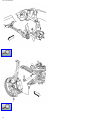
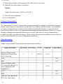
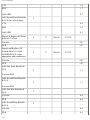
Service Information
<- Back
Forward ->
Document ID# 1564228
2004 Cadillac CTS
Print
Product Safety - Lower Control Arm Washer
#04043B - (Nov 11, 2004)
04043B - Lower Control Arm Washer
2004 Cadillac CTS, SRX, XLR
2004 Chevrolet Corvette
THIS BULLETIN IS BEING REVISED TO ADVISE DEALERS TO ORDER LOWER CONTROL
ARMS AND KNUCKLES, IF NECESSARY, FROM GMSPO RATHER THAN THE PQC.
THIS BULLETIN CANCELS AND REPLACES BULLETIN 04043A ISSUED SEPTEMBER 2004.
PLEASE DISCARD ALL COPIES OF BULLETIN 04043A.
Condition
General Motors has decided that a defect which relates to motor vehicle safety exists in certain 2004
Cadillac CTS, SRX and XLR, and Chevrolet Corvette vehicles. Washers that are used along with nuts to
attach the lower control arms were made of the wrong steel material. These washers may fracture and
become loose or fall away from the vehicle, making it possible for the control arm to separate. If this
were to occur on the front of the vehicle, the affected corner of the vehicle will drop and the affected
wheel could tilt outward, creating a dragging action that would tend to slow the vehicle and turn it in the
direction of the affected corner. The driver could maintain some steering control with the unaffected
wheel, but the vehicle control would be diminished. If the separation occurs at the rear of the vehicle
(XLR and Corvette only), it could cause unexpected right or left lateral forces at the rear of the vehicle.
Although steering of the front wheels would be unaffected, control of vehicle direction would be
impaired.
Front or rear control arm separation may also reduce brake system performance and increase stopping
distance.
If these events occur and the driver is unable to react in time, a crash could occur.
Correction
:57:51 PM
Service Information
Dealers are to install a new nut and washer, and if required, replace the ball stud and/or steering knuckle.
Vehicles Involved
Involved are certain 2004 model year Cadillac CTS, SRX, XLR and Chevrolet Corvette vehicles built
within these VIN breakpoints:
Year
Division
Model
From
Through
2004
Cadillac
CTS
40148760
40183479
2004
Cadillac
SRX
40148762
40183477
2004
Cadillac
XLR
45601754
45603310
2004
Chevrolet
Corvette
45118579
45127798
Important: Dealers should confirm vehicle eligibility through GMVIS (GM Vehicle Inquiry System)
before beginning recall repairs. [Not all vehicles within the above breakpoints may be involved.]
For US
For dealers with involved vehicles, a Campaign Initiation Detail Report containing the complete Vehicle
Identification Number, customer name and address data has been prepared and will be loaded to the GM
DealerWorld, Recall Information website. Dealers that have no involved vehicles currently assigned will
not have a report available in GM DealerWorld.
For Canada
For dealers with involved vehicles, a Campaign Initiation Detail Report containing the complete Vehicle
Identification Number, customer name and address data has been prepared and is being furnished to
involved dealers. Dealers that have no involved vehicles currently assigned will not receive a report with
the recall bulletin.
For IPC
For dealers with involved vehicles, a Campaign Initiation Detail Report containing the complete Vehicle
Identification Number, customer name and address data has been prepared and is being furnished to
involved dealers. Dealers that have no involved vehicles currently assigned will not receive a report with
M
Service Information
the recall bulletin.
The Campaign Initiation Detail Report may contain customer names and addresses obtained from Motor
Vehicle Registration Records. The use of such motor vehicle registration data for any other purpose
other than follow-up necessary to complete this recall is a violation of law in several states/provinces/
countries. Accordingly, you are urged to limit the use of this report to the follow-up necessary to
complete this program.
Parts Information
Parts Pre-Ship Information - For US and Canada
Important: An initial supply of nuts required to complete this recall will be pre-shipped to involved
dealers of record. This pre-shipment is scheduled to begin the week of August 9, 2004 and will be
approximately 20& of each dealer's involved vehicles. Pre-shipped parts will be charged to dealer's open
parts account.
Additional parts, if required, are to be obtained from General Motors Service Parts Operations
(GMSPO). Please refer to your "involved vehicles listing" before ordering parts. Normal orders should
be placed on a DRO=Daily Replenishment Order. In an emergency situation, parts should be ordered on
a CSO=Customer Special Order.
Important: Less than 1% of the population is expected to require replacement of the lower control arm
and knuckle. If the inspection indicates that replacement is required, please order the appropriate part(s)
through GMSPO.
Part Number
Description
Qty
10282253
Nut
2 or 4
Service Procedure
The following procedure provides instructions for inspecting and replacing the nut that attaches the
lower ball joint stud to the knuckle. In a few instances, the results of the inspection may determine that
the lower control arm and knuckle need replacement.
PM
Service Information
M
Service Information
LOWER CONTROL ARM NUTS THAT NEED TO BE INSPECTED
MODEL
INSPECTION
2004 Cadillac CTS and SRX
Both left and right FRONT lower ball joint stud to the
steering knuckle.
2004 Cadillac XLR and Chevrolet
Corvette
Both left and right FRONT AND REAR lower ball joint
stud to the steering knuckle.
Front Lower Ball Joint to Knuckle Retaining Nut Inspection
See the appropriate Service Manual sections for additional information, illustrations and required tool
usage.
1.
2.
3.
4.
5.
Turn the ignition switch to the OFF position so that front wheels can be steered.
Raise the vehicle on a suitable hoist and support as necessary.
On SRX models, remove both front wheel and tire assemblies.
Place a suitable support under the front lower control arm.
Check the torque of the lower ball joint stud to knuckle retaining nut.
A. Was the ball stud nut torque less than 30 N·m (22 lb ft)? If no, nut must be replaced.
Remove the original nut and continue to Step B to determine the corret tightening
specification of the new nut. If yes, the lower control arm (which includes the ball stud),
knuckle, and retaining nut must be replaced. Contact a representative at the PQC to order
parts. Refer to the Parts section in this bulletin for ordering information. Proceed to the
Front Lower Control Arm and Knuckle Replacement Procedure when parts are received.
B. Did the ball stud assembly separate from the knuckle when the nut was removed? If yes,
replace only the nut.
Tighten
Tighten the NEW nut to 30 N·m (22 lb ft), and then an additional 180 degrees.
C. If no, replace only the nut.
Tighten
• CTS/SRX: Tighten the NEW nut to 100 N·m
(74 lb ft).
• XLR/Corvette: Tighten the NEW nut to 75 N·m
(55 lb ft).
6. Remove the support from the lower control arm.
7. Repeat the inspection on the opposite side.
8. On SRX models, install the wheel and tire assemblies.
51 PM
Service Information
Tighten
Tighten the wheel nuts to 140 N·m (103 lb ft).
9. On SRX and CTS models, remove the supports and lower the vehicle.
10. On XLR and Corvette models, proceed to the Rear Lower Ball Joint to Knuckle Retaining Nut
Procedure.
Rear Lower Ball Joint to Knuckle Retaining Nut Inspection - XLR and Corvette Only
See the appropriate Service Manual sections for additional information, illustrations, and required tool
usage.
1.
2.
3.
4.
5.
6.
7.
8.
9.
10.
11.
12.
13.
14.
15.
16.
17.
18.
19.
20.
21.
PM
The vehicle should still be on a hoist with the supports in place as necessary.
Remove both rear wheel and tire assemblies.
Disconnect the linkage attaching the height sensor to the control arm.
Remove the bolts attaching the brake caliper bracket to the knuckle and remove the caliper/
bracket assembly. Support the caliper/bracket assembly as necessary.
Mark the position of the brake rotor on the bearing hub assembly.
Remove the brake rotor.
Remove the outer tie rod and separate the tie rod stud from the knuckle.
Disconnect the wheel speed sensor electrical connector from the bearing hub.
Remove the two bolts attaching the park brake cable to the knuckle and unhook the cable from
the adjuster.
On Corvette models, remove the nuts and stabilizer bar from the lower control arm.
Support the lower control arm as necessary.
Remove the lower shock mounting bolt from the lower control arm.
Remove the large nut attaching the drive axle to the bearing hub.
On Corvette models, remove the snap ring from the leaf spring height adjuster.
On Corvette models, count and record the number of exposed threads between the top of the nut
and the snap ring groove on the height adjuster.
On Corvette models, remove the nut from the height adjuster.
Carefully lower the lower control arm until it is unloaded from the leaf spring.
Remove the upper control arm ball joint stud to knuckle retaining nut.
Separate the upper control arm ball joint stud from the knuckle.
Remove the drive axle from the bearing hub.
Check the torque of the lower ball joint stud to knuckle retaining nut.
A. Was the ball stud nut torque less than 30 N·m (22 lb ft)? If no, the nut must be replaced.
Remove the original nut and continue to Step B to determine the correct tightening
specification of the new nut. If yes, the lower control arm (which includes the ball stud),
knuckle, and retaining nut must be replaced. Proceed to Rear Lower Control Arm and
Service Information
Knuckle Replacement Procedure.
B. Did the ball stud assembly separate from the knuckle when the nut was removed? If yes,
replace only the nut.
Tighten
Tighten the NEW nut to 30 N·m (22 lb ft), and then an additional 180 degrees.
C. If no, replace only the nut.
Tighten
Tighten the NEW nut to 75 N·m (55 lb ft).
22. Install the drive axle into the bearing hub.
23. Install the upper ball joint stud to the knuckle, and install the retaining nut.
Tighten
Tighten the nut to 30 N·m (22 lb ft), and then an additional 180 degrees.
24. Carefully raise the lower control arm.
25. On Corvette models, install the height adjuster bolt and nut.
Tighten
Tighten the nut until the correct amount of threads (recorded earlier) are visible. Install the snap
ring.
26. Install the large nut on the drive axle.
Tighten
Tighten the nut to 160 N·m (118 lb ft).
27. Position the lower shock mount to the lower control arm and install the fasteners.
Tighten
Tighten the bolt (not the nut) to 220 N·m (162 lb ft).
28. On Corvette models, position the stabilizer bar to the lower control arm and install the nut.
Tighten
PM
Service Information
Tighten the nut to 72 N·m (53 lb ft).
29. Position the park brake cable and bracket to the knuckle and install the bolts.
Tighten
Tighten the bolts to 30 N·m (22 lb ft).
30. Connect the outer tie rod to the knuckle and install the nut.
Tighten
Tighten the nut to 20 N·m (15 lb ft), and then an additional 160 degrees.
31. Connect the wheel speed sensor electrical connector to the bearing hub.
32. Using the mark made earlier, align and install the brake rotor to the bearing hub.
33. Position the brake caliper and bracket to the knuckle and install the attaching bolts.
Tighten
Tighten the bolts to 175 N·m (129 lb ft).
34. Connect the height sensor linkage to the control arm.
35. Repeat the inspection procedure on the opposite side of the vehicle.
36. Install the rear wheel and tire assemblies.
Tighten
Tighten the wheel nuts to 140 N·m (103 lb ft).
37. Remove any supports and lower the vehicle.
Front Lower Control Arm and Knuckle Replacement - SRX Models
This procedure should only be performed if the results in the INSPECTION procedure indicate that
replacement of these parts are required.
See the appropriate Service Manual sections for additional information, illustrations, and required tool
usage.
M
Service Information
1. Raise the vehicle on a suitable hoist and support.
2. Remove the front wheel and tire assembly.
3. Remove the bolts attaching the brake caliper bracket to the knuckle and remove the caliper/
bracket assembly. Support the caliper/bracket assembly as necessary.
4. Mark the position of the brake rotor on the bearing hub assembly.
5. Remove the bolt attaching the rotor the bearing hub and remove the rotor.
6. Remove the outer tie rod end nut.
7. Remove the outer tie rod end from the knuckle.
8. Disconnect the ABS wheel speed sensor electrical connector from the bearing hub.
9. Remove the nut attaching the stabilizer bar link to the lower control arm and separate the link
from the arm.
10. Remove the two bolts and remove the bracket that attaches the brake hose and harness to the
knuckle.
11. Place the support under the lower control arm.
12. Remove the nut attaching the upper ball joint stud to the knuckle.
13. Remove the nut attaching the lower ball joint stud to the knuckle.
14. Remove the nut attaching the strut yoke to the lower control arm.
15. On AWD models, remove the large nut attaching the drive axle to the bearing hub.
16. Separate the knuckle from the upper and lower ball studs.
17. On AWD models, remove the knuckle from the drive axle.
18. Disconnect the ABS wiring harness from the lower control arm.
19. Remove the nut attaching the lower control arm to the frame.
20. Remove the bolt attaching the left side of the steering gear to the frame.
21. Loosen, BUT DO NOT REMOVE, the bolt attaching the right side of the steering gear to the
frame.
22. Raise the left side of the steering gear up from the frame to obtain the necessary clearance to
remove the bolt attaching the rear of the lower control arm to the frame.
23. Remove both bolts attaching the lower control arm to the frame.
24. Remove the bolts attaching the bearing hub to the knuckle and remove the bearing hub.
25. Install the hearing hub on the NEW knuckle and install the bolts.
Tighten
Tighten the bolts to 135 N·m (99 lb ft).
26. Position the NEW lower control arm to the frame and install the bolts and nuts. DO NOT tighten
the nuts at this time.
27. Reposition the steering gear into the frame mount and install the left bolt.
Tighten
Tighten both bolts to 120 N·m (88 lb ft).
PM
Service Information
28. Connect the ABS harness to the lower control arm.
29. Install the ball joint stud on the NEW lower control arm to the NEW knuckle and install the nut.
Tighten
Tighten the nut to 20 N·m (15 lb ft), and then an additional 210 degrees.
30. On AWD models, install the drive axle into the bearing hub.
31. Install the ball joint stud on the upper control arm to the NEW knuckle and install the nut.
Tighten
Tighten the nut to 20 N·m (15 lb ft), and then an additional 210 degrees.
32. Install the large nut on the drive axle.
Tighten
Tighten the nut to 160 N·m (118 lb ft).
33. Attach the strut yoke to the lower control arm and install the nut.
Tighten
Tighten the nut to 180 N·m (133 lb ft).
34. Position the bracket for the brake hose to the knuckle and install the bolts.
Tighten
Tighten the NEW nut to 30 N·m (22 lb ft), and then an additional 180 degrees.
35. Connect the stabilizer link to the lower control arm and install the nut.
Tighten
Tighten the nut to 110 N·m (81 lb ft).
36. Connect the ABS electrical connector to the bearing hub.
37. Connect the outer tie rod end to the knuckle and install the nut.
Tighten
PM
Service Information
Tighten the nut to 70 N·m (52 lb ft).
38. Align the rotor to the mark made earlier and install on the hub.
39. Install the bolt attaching the rotor to the hub.
Tighten
Tighten the bolt to 14 N·m (124 lb in).
40. Position the brake caliper/bracket assembly on the knuckle and install the attaching bolts.
Tighten
Tighten the bolts to 130 N·m (96 lb ft).
41. Place supports under the lower control arm to raise the arm to normal curb height position.
Tighten
Tighten the lower control arm attaching bolt and nuts to 135 N·m (99 lb ft).
42. Install the front wheel/tire assembly.
Tighten
Tighten the wheel nuts to 140 N·m (103 lb ft).
43. Repeat the procedure on the opposite side of the vehicle if necessary.
44. Check the wheel alignment.
45. Lower the vehicle.
Front Lower Control Arm and Knuckle Replacement - CTS Models
This procedure should only be performed if the results in the INSPECTION procedure indicate that
replacement of these parts are required.
See the appropriate Service Manual sections for additional information, illustrations, and required tool
usage.
1. Raise the vehicle on a suitable hoist and support.
2. Remove the wheel and tire assembly.
51 PM
Service Information
3. Remove the bolts attaching the brake caliper bracket to the knuckle and remove the caliper/
bracket assembly. Support the caliper/bracket assembly as necessary.
4. Mark the position of the brake rotor on the bearing hub assembly.
5. Remove the bolt attaching the rotor the bearing hub and remove the rotor.
6. Remove the outer tie rod end nut.
7. Separate the outer tie rod end from the knuckle.
8. Remove the three bolts attaching the bearing hub to the knuckle.
9. Remove the bearing hub from the knuckle and disconnect the electrical connector from the
backing plate. Route the electrical connector and harness through the knuckle.
10. Remove the bolts attaching the shock absorber to the lower control arm.
11. Remove the stabilizer link nut and disconnect the link from the lower control arm.
12. Place a support under the lower control arm.
13. Remove the nut attaching the lower ball joint stud to the knuckle.
14. Separate the lower control arm ball stud from the knuckle and carefully lower the lower control
arm.
15. Remove the nut attaching the upper ball joint stud to the knuckle.
16. Separate the upper ball joint stud from the knuckle and remove the knuckle from the vehicle.
17. Remove the three ABS harness clips from the lower control arm.
18. Remove the nuts and bolts that attach the lower control arm to the frame.
19. Install the NEW lower control arm to the frame and install the bolts and nuts. DO NOT tighten
the nuts at this time.
20. Install the three ABS harness clips to the new lower control arms.
21. Install the ball joint stud on the NEW lower control arm to the NEW knuckle and install the nut.
Tighten
Tighten the nut to 20 N·m (15 lb ft), and then an additional 210 degrees.
22. Carefully raise the support under the lower control arm, install the ball joint stud on the upper
control arm to the NEW knuckle, and install the nut.
Tighten
Tighten the nut to 20 N·m (15 lb ft), and then an additional 210 degrees.
23. Position the stabilizer link to the lower control arm and install the nut.
Tighten
Tighten the nut to 50 N·m (37 lb ft).
24. Position the shock absorber to the lower control arm and install the bolts.
1 PM
Service Information
Tighten
Tighten the bolts to 25 N·m (18 lb ft).
25. Route the electrical connector and harness through the knuckle and connect the connector to the
backing plate.
26. Position the bearing hub to the knuckle and install the three bolts.
Tighten
Tighten the bolts to 135 N·m (99 lb ft).
27. Install the outer tie rod end to the knuckle and install the nut.
Tighten
Tighten the nut to 75 N·m (55 lb ft).
28. Using the mark made earlier, align the brake rotor to the bearing hub and install the retaining
screw.
Tighten
Tighten the screw to 14 N·m (124 lb in).
29. Install the brake caliper and bracket assembly to the knuckle and install the two bolts.
Tighten
Tighten the bolts to 136 N·m (100 lb ft).
30. Place supports under the lower control arm to raise the arm to the normal curb height position.
Tighten
Tighten the lower control arm nuts to 135 N·m (99 lb ft).
31. Install the wheel and tire assembly.
Tighten
Tighten the wheel nuts to 140 N·m (103 lb ft).
1 PM
Service Information
32. Repeat the procedure on the opposite side of the vehicle if necessary.
33. Check the wheel alignment.
34. Lower the vehicle.
Front Lower Control Arm and Knuckle Replacement - XLR and Corvette Models
This procedure should only be performed if the results in the INSPECTION procedure indicate that
replacement of these parts are required.
See the appropriate Service Manual sections for additional information, illustrations, and required tool
usage.
1. Raise the vehicle on a suitable hoist and support.
2. Remove the wheel and tire assembly.
3. Remove the bolts attaching the brake caliper bracket to the knuckle and remove the caliper/
bracket assembly. Support the caliper/bracket assembly as necessary.
4. Mark the position of the brake rotor on the bearing hub assembly.
5. Remove the brake rotor.
6. Remove the outer tie rod end nut and separate the stud from the knuckle.
7. Disconnect the wheel speed sensor electrical connector.
8. Remove the stabilizer link nut and disconnect the link from the lower control arm.
9. Disconnect the linkage for the ride height sensor.
10. Remove the bolts attaching the shock absorber to the lower control arm.
11. Place supports under the lower control arm.
12. Remove the nut attaching the upper control arm ball joint stud to the knuckle.
13. Separate the upper control arm ball stud from the knuckle.
14. Remove the nut attaching the lower control arm ball joint stud to the knuckle.
15. Separate the lower control arm ball stud from the vehicle and carefully lower the lower control
arm.
16. Remove the knuckle from the vehicle.
17. Remove the bolts attaching the bearing hub to the knuckle.
18. Transfer the bearing hub to NEW knuckle and install the bolts.
Tighten
Tighten the bolts to 130 N·m (96 lb ft).
19. Remove the screw for the ABS harness mounting bracket and transfer the bracket and screw to
the NEW knuckle.
Tighten
PM
Service Information
Tighten the screw to 3 N·m (27 lb in).
20. Remove the screw for the ABS harness bracket on the lower control arm.
21. Remove the nuts and bolts that attach the lower control arm to the frame and remove the lower
control arm.
22. Install the NEW lower control arm to the frame and install the bolts and nuts. DO NOT tighten at
this time.
23. Install the ABS harness bracket to the NEW lower control arm and install the screw.
Tighten
Tighten the screw to 3 N·m (27 lb in).
24. Install the ball joint stud on the NEW lower control arm to the NEW knuckle and install the nut.
Tighten
Tighten the bolts to 20 N·m (15 lb ft), and then an additional 210 degrees.
25. Carefully raise the support under the lower control arm, install the ball joint stud on the upper
control arm to the NEW knuckle, and install the nut.
Tighten
Tighten the nut to 20 N·m (15 lb ft), then an additional 210 degrees.
26. Position the shock absorber to the lower control arm and install the attaching bolts.
Tighten
Tighten the bolts to 28 N·m (21 lb ft).
27. Connect the ride height sensor linkage.
28. Position the stabilizer bar to the lower control arm and install the nut.
Tighten
Tighten the nut to 72 N·m (53 lb ft).
29. Connect the wheel speed sensor electrical connector.
30. Connect the outer tie rod end to the knuckle and install the nut.
PM
Service Information
Tighten
Tighten the nut to 20 N·m (15 lb ft), then an additional 160 degrees.
31. Using the mark made earlier, align and install the brake rotor.
32. Install the brake caliper and bracket assembly to the knuckle and install the two bolts.
Tighten
Tighten the bolts to 175 N·m (129 lb ft).
33. Place the supports under the lower control arm to raise the arm to the normal curb height
position.
Tighten
Tighten the lower control arm nuts to 175 N·m (129 lb ft).
34. Install the front wheel and tire assembly.
Tighten
Tighten the wheel nuts to 140 N·m (103 lb ft).
35. Repeat the procedure on the opposite side of the vehicle if necessary.
36. Check the wheel alignment.
37. Lower the vehicle.
Rear Lower Control Arm and Knuckle Replacement - XLR and Corvette
2004 Cadillac XLR & Chevrolet Corvette
This procedure should only be performed if the results in the INSPECTION procedure indicate that
replacement of these parts are required.
See the appropriate Service Manual sections for additional information, illustrations, and required tool
usage.
Important: This procedure is based on the vehicle being partially disassembled in the INSPECTION
procedure.
PM
Service Information
1.
2.
3.
4.
Remove the lower ball joint stud to knuckle retaining nut.
Separate the knuckle from the lower control arm.
Remove the bolts attaching the bearing hub and park brake assembly to the knuckle.
Install the bearing hub and park brake assembly and the bolts on the new knuckle.
Tighten
Tighten the bolts to 130 N·m (96 lb ft).
5. Remove the nuts from the bolts that attach the lower control arm to the frame.
Important: On Corvette models, the clearance for removal of the left side front bolt is limited,
however it can be removed.
6. Position the new control arm to the frame and install the bolts and nuts. DO NOT tighten at this
time.
7. Install the lower ball joint stud in the knuckle and install a NEW nut.
Tighten
Tighten the nut to 20 N·m (15 lb ft), and then an additional 210 degrees.
8. Install the drive axle into the bearing hub.
9. Install the upper ball joint stud to the knuckle and install the retaining nut.
Tighten
Tighten the nut to 30 N·m (22 lb ft), and then an additional 180 degrees.
10. Carefully raise the lower control arm.
11. On Corvette models, install the height adjuster bolt and nut.
Tighten
Tighten the nut until the correct amount of threads (recorded earlier) are visible. Install the snap
ring.
12. Install the large nut on the drive axle.
Tighten
Tighten the nut to 160 N·m (118 lb ft).
M
Service Information
13. Position the lower shock mount to the lower control arm and install the fasteners.
Tighten
Tighten the bolt (not the nut) to 220 N·m (162 lb ft).
14. On Corvette models, position the stabilizer bar to the lower control arm and install the nut.
Tighten
Tighten to 72 N·m (53 lb ft).
15. Attach the park brake cable to the adjuster, position the park brake cable bracket to the knuckle,
and install the two bolts.
Tighten
Tighten to 30 N·m (22 lb ft).
16. Connect the outer tie rod to the knuckle and install the nut.
Tighten
Tighten to 20 N·m (15 lb ft), and then an additional 160 degrees.
17. Connect the wheel speed sensor electrical connector to the bearing hub.
18. Using the mark made earlier, align and install the brake rotor.
19. Position the brake caliper and bracket to the knuckle and install the bolts.
Tighten
Tighten to 175 N·m (129 lb ft).
20. Connect the height sensor linkage to the control arm.
21. Place supports under the lower control arm to raise the arm to the normal curb height position.
Tighten
• Tighten the FRONT lower control arm nuts to 145 N·m
(107 lb ft).
• Tighten the REAR lower control arm nuts to 95 N·m
(70 lb ft).
22. Remove the supports from the lower control arm.
PM
Service Information
23. Repeat the procedure on the opposite side of the vehicle if necessary.
24. Install the rear wheel and tire assemblies.
Tighten
Tighten the wheel nuts to 140 N·m (103 lb ft).
25. Check the wheel alignment.
26. Lower the vehicle.
Courtesy Transportation
The General Motors Courtesy Transportation program is intended to minimize customer inconvenience
when a vehicle requires a repair that is covered by the New Vehicle Limited Warranty. The availability
of courtesy transportation to customers whose vehicles are within the warranty coverage period and
involved in a product recall is very important in maintaining customer satisfaction. Dealers are to ensure
that these customers understand that shuttle service or some other form of courtesy transportation is
available and will be provided at no charge. Dealers should refer to the General Motors Service Policies
and Procedures Manual for Courtesy Transportation guidelines.
Claim Information
Submit a Product Recall Claim with the information indicated below:
Repair Performed
Inspect & Replace Both
Front Lower Control Arm
(LCA) Nuts Only
Part Count Parts Allow
2
**
CC-FC
Labor Op
MA-96
V1232
Labor Hours
CTS
0.4*
SRX
0.5*
Inspect & Replace Both
LCA Nuts AND REPLACE
(select appropriate add
condition(s)):
V1233
CTS
0.4*
SRX
0.5*
Add: One Front Knuckle &
LCA (inc. wheel align)
PM
2
Service Information
CTS
1.6
SRX
1.7
Add AWD
0.1
Add: Second Front Knuckles
& LCA (inc. wheel align)
2
CTS
0.9
SRX
1.0
Add AWD
0.1
Inspect & Replace All Front
& Rear LCA Nuts
4
**
MA-96
V1234
Corvette
2.0*
XLR
1.9*
Inspect and Replace All
Front & Rear LCA Nuts
AND REPLACE (select
appropriate add condition(s):
4
**
MA-96
V1235
Corvette
2.0*
XLR
1.9*
Add: One Front Knuckle &
LCA
2
1.1
2
1.1
Corvette/XLR
Add: Second Front Knuckle
& LCA
Corvette/XLR
Add: One Rear Knuckle &
LCA
2
Corvette
0.6
XLR
0.5
Add: Second Rear Knuckle
& LCA
2
Corvette
0.6
XLR
0.5
PM
Service Information
Add: Wheel Alignment
(when replacing control arm/
knuckle)
N/A
Courtesy Transportation
N/A
0.7
N/A
MA-96
***
N/A
* -- For Recall Administrative Allowance, add 0.1 hours to the "Labor Hours".
** -- The "Parts Allowance" should be the sum total of the current GMSPO Dealer net price plus
applicable Mark-Up or Landed Cost Mark-Up (for IPC) for the parts needed to complete the repair.
*** -- Submit courtesy transportation using normal labor operations for courtesy transportation as
indicated in the GM Service Policies and Procedures Manual.
Refer to the General Motors WINS Claims Processing Manual for details on Product Recall Claim
Submission.
Customer Notification -- For US and Canada
General Motors will notify customers of this recall on their vehicle (see copy of customer letter included
with this bulletin).
Customer Notification -- For IPC
Letters will be sent to known owners of record located within areas covered by the US National Traffic
and Motor Vehicle Safety Act. For owners outside these areas, dealers should notify customers using the
attached sample letter.
Dealer Recall Responsibility -- For US and IPC (US States, Territories, and Possessions)
The US National Traffic and Motor Vehicle Safety Act provides that each vehicle which is subject to a
recall of this type must be adequately repaired within a reasonable time after the customer has tendered
it for repair. A failure to repair within sixty days after tender of a vehicle is prima facie evidence of
failure to repair within a reasonable time. If the condition is not adequately repaired within a reasonable
time, the customer may be entitled to an identical or reasonably equivalent vehicle at no charge or to a
refund of the purchase price less a reasonable allowance for depreciation. To avoid having to provide
these burdensome remedies, every effort must be made to promptly schedule an appointment with each
customer and to repair their vehicle as soon as possible. In the recall notification letters, customers are
told how to contact the US National Highway Traffic Safety Administration if the recall is not
completed within a reasonable time.
Dealer Recall Responsibility -- All
PM
Service Information
All unsold new vehicles in dealers' possession and subject to this recall MUST be held and inspected/
repaired per the service procedure of this recall bulletin BEFORE customers take possession of these
vehicles.
Dealers are to service all vehicles subject to this recall at no charge to customers, regardless of mileage,
age of vehicle, or ownership, from this time forward.
Customers who have recently purchased vehicles sold from your vehicle inventory, and for which there
is no customer information indicated on the dealer listing, are to be contacted by the dealer.
Arrangements are to be made to make the required correction according to the instructions contained in
this bulletin. A copy of the customer letter is provided in this bulletin for your use in contacting
customers. Recall follow-up cards should not be used for this purpose, since the customer may not as yet
have received the notification letter.
In summary, whenever a vehicle subject to this recall enters your vehicle inventory, or is in your
dealership for service in the future, please take the steps necessary to be sure the recall correction has
been made before selling or releasing the vehicle.
August 2004
Dear General Motors Customer:
This notice is sent to you in accordance with the requirements of the National Traffic and Motor Vehicle
Safety Act.
Reason For This Recall
General Motors has decided that a defect which relates to motor vehicle safety exists in certain 2004
Cadillac CTS, SRX and XLR, and Chevrolet Corvette vehicles. Washers that are used along with nuts to
attach the lower control arms were made of the wrong steel material. These washers may fracture and
become loose or fall away from the vehicle, making it possible for the control arm to separate. If this
were to occur on the front of the vehicle, the affected corner of the vehicle will drop and the affected
wheel could tilt outward, creating a dragging action that would tend to slow the vehicle and turn it in the
direction of the affected corner. The driver could maintain some steering control with the unaffected
wheel, but the vehicle control would be diminished. If the separation occurs at the rear of the vehicle
(XLR and Corvette only), it could cause unexpected right or left lateral forces at the rear of the vehicle.
Although steering of the front wheels would be unaffected, control of vehicle direction would be
impaired.
Front or rear control arm separation may also reduce brake system performance and increase stopping
distance.
PM
Service Information
If these events occur and the driver is unable to react in time, a crash could occur.
What Will Be Done
Dealers are to install a new nut and washer on the lower control arms, and if required, replace the ball
stud and/or steering knuckle(s). This service will be performed for you at no charge .
How Long Will The Repair Take?
Depending on the service correction required, this inspection and service correction will take
approximately 25
minutes to 2 hours and 10 minutes for CTS and SRX vehicles, and approximately 2 hours to 6-1/2 hours
for Corvette and XLR vehicles. However, due to scheduling requirements, your dealer may need your
vehicle for a longer period of time.
Contacting Your Dealer
To limit any possible inconvenience, we recommend that you contact your GM dealer as soon as
possible to schedule an appointment for this repair. By scheduling an appointment, your dealer can
ensure that the necessary parts will be available on your scheduled appointment date.
Should your dealer be unable to schedule a service date within a reasonable time, you should contact the
appropriate Customer Assistance Center at the number listed below. The Customer Assistance Center
hours of operation are from 8:00 AM - 11:00 PM eastern standard time Monday through Friday.
Division
Number
Text Telephones (TTY)
Cadillac
1-866-982-2339
1-800-833-2622
Chevrolet
1-800-630-2438
1-800-833-2622
Puerto Rico - English
1-800-496-9992
Puerto Rico - Español
1-800-496-9993
Virgin Islands
1-800-496-9994
If, after contacting the appropriate customer assistance center, you are still not satisfied that we have
done our best to remedy this condition without charge and within a reasonable time, you may wish to
write the Administrator, National Highway Traffic Safety Administration, 400 Seventh Street SW,
Washington, DC 20590 or call 1-888-327-4236.
Service Information
Customer Reply Form
The enclosed customer reply form identifies your vehicle. Presentation of this form to your dealer will
assist in making the necessary correction in the shortest possible time. If you no longer own this vehicle,
please let us know by completing the form and mailing it back to us.
Courtesy Transportation
If your vehicle is within the New Vehicle Limited Warranty your dealer may provide you with shuttle
service or some other form of courtesy transportation while your vehicle is at the dealership for this
repair. Please refer to your Owner's Manual and your dealer for details on Courtesy Transportation.
Recall Information Online
More information about this recall (including frequently asked questions) is available online at the
Owner Center at My GMLink. This free online service offers vehicle and ownership-related information
and tools tailored to your specific vehicle. To join, visit www.mygmlink.com and enter your vehicle's 17character vehicle identification number (VIN) shown on the enclosed form to get the most personalized
information for your vehicle.
Federal regulation requires that any vehicle lessor receiving this recall notice must forward a copy of
this notice to the lessee within ten days.
We are sorry to cause you this inconvenience; however, we have taken this action in the interest of your
safety and continued satisfaction with our products.
General Motors Corporation
Enclosure
04043
GM bulletins are intended for use by professional technicians, NOT a "do-it-yourselfer". They
are written to inform these technicians of conditions that may occur on some vehicles, or to
provide information that could assist in the proper service of a vehicle. Properly trained
technicians have the equipment, tools, safety instructions, and know-how to do a job properly
and safely. If a condition is described, DO NOT assume that the bulletin applies to your vehicle,
or that your vehicle will have that condition. See your GM dealer for information on whether
your vehicle may benefit from the information.
© Copyright General Motors Corporation. All Rights Reserved.
WE SUPPORT
VOLUNTARY
TECHNICIAN
CERTIFICATION
Service Information
<- Back
Forward ->
Document ID# 1564228
2004 Cadillac CTS
Print