1
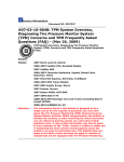
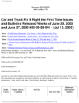
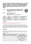
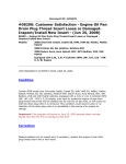
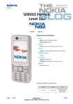
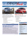
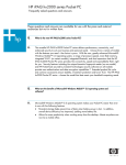
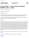
Recall Bulletin
File In Section: Product Recalls
Bulletin No.: 04006C
Date: February 2006
PRODUCT SAFETY RECALL
SUBJECT:
ELECTRONIC COLUMN LOCK SYSTEM
MODELS:
1997-2004 CHEVROLET CORVETTE EQUIPPED WITH A MANUAL
TRANSMISSION
1997-2000 CHEVROLET CORVETTE EQUIPPED WITH AN AUTOMATIC
TRANSMISSION
2001-2004 CHEVROLET CORVETTE EQUIPPED WITH AN AUTOMATIC
TRANSMISSION – EUROPEAN EXPORT ONLY
THIS BULLETIN CANCELS AND REPLACES BULLETIN 04006B, ISSUED
NOVEMBER 2004.
THE SERVICE PROCEDURE FOR U.S. VEHICLES EQUIPPED WITH A MANUAL
TRANSMISSION HAS BEEN REVISED. PLEASE REVIEW THIS NEW INFORMATION
IMMEDIATELY.
ALL COPIES OF BULLETIN 04006B SHOULD BE DESTROYED.
CONDITION
General Motors has decided that a defect, which relates to motor vehicle safety, exists in
certain 1997-2004 model year Chevrolet Corvette vehicles. When you remove the ignition
key, the electronic column lock (ECL) system prevents turning of the steering wheel. When
the vehicle is started, it unlocks the steering. Two conditions can prevent steering while the
vehicle is moving:
1.
2.
The vehicle is designed so that if the column fails to unlock when the vehicle is started,
the fuel supply will be shut off if the driver tries to move the vehicle. If voltage at the
powertrain control module is low or interrupted, however, the fuel shut off may not
occur and the vehicle can be accelerated while the steering is locked.
During quick cranks, the ECL lock pin may not withdraw fully and, in vehicles where
there is abnormally low clearance to the lock plate, there may be contact between the
pin and lock plate. This can cause a noise or ratcheting when the steering wheel is
turned or, if there is insufficient clearance, the steering wheel cannot be turned.
If one of these conditions occurs, a crash could occur without warning.
Copyright 2006 General Motors Corporation. All Rights Reserved.
Page 2
February 2006
Bulletin No.: 04006C
CORRECTION
Dealers are to remove the column lock plate on U.S. and Canadian vehicles equipped with
an automatic transmission and U.S. vehicles equipped with a manual transmission. After
the service correction, the steering column will no longer lock when the key is removed.
On Canadian and export vehicles equipped with a manual transmission, and export
vehicles equipped with an automatic transmission, dealers are to 1) reprogram the PCM,
and 2) verify there is adequate lock plate clearance and, if necessary, replace the lock
plate. After the service correction, the steering column will continue to lock when the key is
removed.
VEHICLES INVOLVED
Involved are certain 1997-2004 Chevrolet Corvettes equipped with a manual transmission,
1997-2000 Chevrolet Corvettes equipped with an automatic transmission, and 2001-2004
Chevrolet Corvette equipped with automatic transmission (European export only), built
within these VIN breakpoints:
YEAR
1997
1998
1999
2000
2001
2002
2003
2004
DIVISION
Chevrolet
Chevrolet
Chevrolet
Chevrolet
Chevrolet
Chevrolet
Chevrolet
Chevrolet
MODEL
Corvette
Corvette
Corvette
Corvette
Corvette
Corvette
Corvette
Corvette
FROM
V5100001
W5100001
X5100001
Y5100001
15100001
25100002
35100003
45100001
THROUGH
V5109707
W5131069
X5133283
Y5133610
15135601
25135762
35135465
45120862
IMPORTANT: Dealers should confirm vehicle eligibility through GMVIS (GM Vehicle
Inquiry System) prior to beginning recall repairs. [Not all vehicles within the
above breakpoints may be involved.]
For US and Canada: For GM dealers, Canadian Saab dealers, and Canadian Saturn
retailers with involved vehicles, a Campaign Initiation Detail Report (CIDR) containing the
complete vehicle identification number, customer name and address data has been
prepared and will be loaded to the GM DealerWorld (US) Recall Information, GMinfoNet
(Canada) Recall Reports. For US Saturn retailers only, the involved vehicles are provided
in a Facility VIN List file sent to you at your current email address. Dealers/retailers will not
have a report available if they have no involved vehicles currently assigned.
For Export: For dealers with involved vehicles, a Campaign Initiation Detail Report
containing the complete vehicle identification number, customer name and address data
has been prepared, and is being furnished to involved dealers. Dealers will not receive a
report with the recall bulletin if they have no involved vehicles currently assigned.
The Campaign Initiation Detail Report may contain customer names and addresses
obtained from Motor Vehicle Registration Records. The use of such motor vehicle
registration data for any purpose other than follow-up necessary to complete this recall is a
violation of law in several states/provinces/countries. Accordingly, you are urged to limit
the use of this report to the follow-up necessary to complete this recall.
Page 3
February 2006
Bulletin No.: 04006C
PARTS INFORMATION
Parts required to complete this recall are to be obtained from General Motors Service Parts
Operations (GMSPO). Please refer to your “involved vehicles listing” before ordering parts.
Normal orders should be placed on a DRO = Daily Replenishment Order. In an emergency
situation, parts should be ordered on a CSO = Customer Special Order.
Part Number
89023816
88952428
26056108
26094767
88964588
05694191
Description
Harness Kit, Strg Whl Theft Dtrnt Lk Shorting
(U.S. manuals and all automatics except export
vehicles)
Wire Kit, Strg Whl Theft Dtrnt Lk
(1998-2000 Canadian and export manuals & export
automatics)
Nut, Strg Whl
Plate, Strg Shf Lk (Canadian manuals)
Plate, Strg Shf Lk (export)
Ring, Strg Shf Lk Plt Ret
Quantity/Vehicle
1
1 (If Req’d)
1 (If Req’d)
1 (If Req’d)
1 (If Req’d)
1 (If Req’d)
SERVICE PROCEDURE
The required repairs vary depending on the model year, build date, and whether Customer
Satisfaction Program 01044 or Technical Service Bulletin 01-02-35-008 has previously
been performed. Refer to the chart below to determine the correct repairs for the vehicle
you are working on. After determining the required repairs for the vehicle you are working
on, proceed to the appropriate service procedure.
Models
1997 – 2000
Automatic
(except export
vehicles)
All
1997-2004 U.S.
Manual
All
PROCEDURE
1A
PROCEDURE
1B
PROCEDURE
2
Install Wire
Kit 89023816
Install Wire
Kit 88952428
Reprogram
PROCEDURE
3
Functional Test
Tech 2
Tech 2
W/SPX Tool
X
X
1997 – All
Canadian
Manual & All
Export
All
Continued on next page
X
X
Page 4
Models
1998 – All
Canadian
Manual & All
Export
Built through
5/25/98
Built on or after
5/26/98 and
CSC 01044 was
performed
(V0743)
Built on or after
5/26/98 and
CSC 01044 was
not performed
(V0743)
1999-2000 – All
Canadian
Manual & All
Export
CSC 01044 or
TSB 01-02-35008 (V0743 or
N8505) was
performed
CSC 01044 or
TSB 01-02-35008 was not
performed
(V0743 or
N8505)
2001-2004 – All
Canadian &
Export Manual &
All European
Export
Automatic
All
February 2006
PROCEDURE
1A
PROCEDURE
1B
PROCEDURE
2
Install Wire
Kit 89023816
Install Wire
Kit 88952428
Reprogram
Bulletin No.: 04006C
PROCEDURE
3
Functional Test
Tech 2
Tech 2
W/SPX Tool
X
X
X
X
X
X
X
X
X
X
X
X
X
X
Page 5
February 2006
Bulletin No.: 04006C
1997-2000 Corvettes Equipped With Automatic Transmission (Excludes Export
Vehicles), and all U.S. Manual Transmission (Procedure 1A)
The following service procedure provides instructions for disconnecting the electric column
lock (ECL) on vehicles equipped with an automatic transmission, and on all U.S. manual
transmissions. DO NOT use this procedure on Canadian vehicles equipped with a manual
transmission or on any export vehicles.
•
•
•
•
Tools Required
J 1859-A Steering Wheel Puller
J 42120 Steering Wheel Puller Legs
J 23653 SIR, Steering Column Lock Plate Compressor
J 42137 Cam Orientation Plate Adaptor
Important: Disregard all instruction sheets that may be in the harness kit, and follow
the instructions provided in this service procedure.
1.
2.
3.
Turn the steering wheel so that the vehicle's front wheels are pointing straight ahead.
Turn the ignition switch to the OFF position.
Open the hood and disconnect the negative battery cable.
71195
4.
5.
6.
Disengage the upper latches on the front floor kick-up panel on the passenger side.
Lift the kick-up panel's lower edge out of the slots in the relay bracket.
Remove the SDM fuse from the IP fuse block located behind the kick-up panel that
was just removed.
Page 6
February 2006
Bulletin No.: 04006C
64671
7.
Using a flat-bladed tool, carefully pry the IP courtesy lamp assembly from the driver's
side lower closeout panel.
95689
8.
9.
Remove the push-on retaining nut from the steering column bracket stud.
Release the driver's side lower closeout panel push-in retainers from the IP lower
support beam.
10. Insert the IP courtesy lamp assembly up through the opening in the closeout panel.
11. Lower and remove the closeout panel. Release the notch, in the right-hand forward
edge of the closeout panel, from the tab on the accelerator pedal bracket.
Page 7
February 2006
Bulletin No.: 04006C
68614
12. Remove the connector position assurance (CPA) from the driver's yellow 2-way air bag
connector located at the base of the steering column and disconnect the connector.
68617
13. Remove the CPA from the passenger yellow 2-way air bag connector, also located at
the base of the steering column, and disconnect the connector.
14. Remove the screws attaching the driver's inflator module to the steering wheel (3) and
pull the module away from the steering wheel.
15. Disconnect the SIR electrical connector (2) from the backside of the module, the horn
wiring harness connector (6) from the steering column, and the ground wire (5) from
the steering column. Remove the module.
16. Remove the nut attaching the steering wheel to the column and discard the nut.
Page 8
February 2006
Bulletin No.: 04006C
70114
17. Using tool J 1859-A, Steering Wheel Puller, and J 42120, Steering Wheel Puller Legs,
remove the steering wheel from the column.
82174
18. Using a small flat-bladed screwdriver, release the locking tab from the tilt lever handle
and pull the lever straight out.
Page 9
February 2006
Bulletin No.: 04006C
158135
19. Using a small flat-bladed screwdriver, pry the lower edge of the combination fog
lamp/trunk release switch to release the locking tab. Disconnect the electrical
connector from the switch. Repeat this step on the inside air temperature grill located
to the right side of the steering column.
95692
Important: When removing the driver's side knee bolster trim panel as described
below, care must be taken not to damage the console trim plate as the knee
bolster trim panel tucks in behind the console trim plate.
20. Remove the driver's side knee bolster trim panel retaining screw, located behind the
area where the combination fog lamp/trunk release switch is installed. Repeat this step
on the screw located in the inside air temperature cavity.
21. Remove the driver's side knee bolster trim panel lower retaining screws.
22. Grasp the trim panel at the side edges and firmly pull rearward to release the locking
tabs and remove the panel.
23. If equipped, disconnect the electrical connector from the inside air temperature sensor.
Page 10
February 2006
Bulletin No.: 04006C
73209
24. Remove the two screws that attach the lower steering column cover (3) to the upper
(1).
25. Remove the one screw that attaches the upper steering column cover to the column
and remove the upper cover.
26. Remove the snap ring and SIR coil from the steering column.
1489425
Notice: Tool J 23653-SIR MUST be used when removing the retaining ring and
lock plate in the next step.
27. Using J 23653-SIR (2), remove the retaining ring and the lock plate (1) and discard
both.
Page 11
February 2006
Bulletin No.: 04006C
1489468
28. Align and position the cam orientation plate (1), included in the kit, on the steering
column shaft.
1489426
Notice: When installing the cam orientation plate in the next step, a NEW
retaining ring must be used. Do not reuse the original retaining ring.
J 23653-SIR and J 42137 MUST be used when installing the cam orientation plate
and new retaining ring in the next step. Failure to use these tools may result in
damage to the cam orientation plate, retaining ring or steering column
components.
29. Using J 23653-SIR (2) and J 42137 (1), install the cam orientation plate and the new
retaining ring included in the recall kit. The cam orientation plate replaces the lock
plate removed in the previous step.
30. Position the SIR coil on the steering column and install the snap ring.
31. Disconnect the electrical connector from the ECL, located on the right lower side of the
steering column.
32. Attach the NEW relay (1) and harness, included in the kit, to the left IP brace as shown
and secure with plastic tie straps.
33. Route the NEW relay harness over the knee bolster.
Page 12
February 2006
Bulletin No.: 04006C
Important: The connectors on the NEW relay harness are specific and MUST be
connected correctly in the next steps. When connected the new connection
becomes J165/P165.
34. Connect one end of the NEW relay harness into the connector on the ECL. Connect
the other end on the NEW relay harness into the connector that was disconnected from
the ECL in Step 31.
35. Install the upper steering column cover and install the attaching screw.
Tighten
Tighten the screw to 1.9 N·m (17 lb in).
36. Install the lower steering column and attaching screws.
Tighten
Tighten the screws to 4 N·m (35 lb in).
37. If equipped, connect the electrical connector to the inside air temperature sensor
located on the knee bolster trim panel.
38. Install the knee bolster trim panel and press firmly to engage the locking tabs.
39. Install the lower retaining screws and the screws located behind the combination fog
lamp/trunk release switch, and the inside air temperature sensor grill.
Tighten
Tighten the screws to 1.8 N·m (16 lb in).
40. Connect the electrical connector to the combination fog lamp/trunk release switch and
install the assembly into the opening in the IP. Press firmly to secure. Repeat this step
on the inside air temperature sensor grill.
41. Slide the tilt lever in the steering column until the locking tab clicks into place.
42. Remove the inflatable restraint module retaining screws from the steering wheel.
43. Position, align, and press the steering wheel onto the steering column shaft.
44. Install a NEW steering wheel set nut on the steering column shaft.
Tighten
Tighten the nut to 41 N·m (30 lb ft).
45. Install the retaining screws removed from the steering wheel into the backside of the
inflatable restraint module.
Tighten
Tighten the screws to 6 N·m (53 lb in).
46. Position the inflatable restraint module to the steering wheel and connect the SIR
electrical connector, the horn wiring harness connector to the steering column, and the
ground wire to the column.
47. Install the inflatable restraint module on the steering wheel by pushing on both the right
and left sides of the module until the retaining screws snap into place.
48. Connect the passenger yellow 2-way air bag connector located at the base of the
steering column, and install the CPA.
Page 13
February 2006
Bulletin No.: 04006C
49. Connect the driver's yellow 2-way air bag connector located at the base of the steering
column, and install the CPA.
50. Position the driver's side lower closeout panel below the IP and install the courtesy
lamp.
51. Raise the closeout panel to the IP and engage the push-in retainers to the IP lower
support beam.
52. Align the right-hand forward edge of the panel to the tab on the accelerator pedal
bracket. Push up to secure.
53. Install the push-on retaining nut to the steering column bracket stud.
54. Install the SDM fuse.
55. Position the kick-up panel to the opening in the floor and insert the lower tabs into the
slots in the multi-use bracket.
56. Close the panel and latches.
57. Connect the negative battery cable and close the hood.
58. Verify that the ECL and relay are synchronized:
Depending on the position of the relay and the ECL bolt, when the key (ignition
switch) is first turned to the ON position, you may receive the message "Pull Key
and Wait 10 Sec."
ο
If you do NOT receive this message, the ECL and relay ARE synchronized. No
further action is required.
ο
If you DO receive this warning message, the ECL and relay are NOT
synchronized. To synchronize, turn the ignition switch to the OFF position and
REMOVE THE KEY from the switch (lock cylinder). Wait a MINIMUM of 10
seconds, re-insert the key, and turn to the ON position. From this point on, the
ECL and relay should be synchronized.
59. Start the engine and verify that the steering column in unlocked.
1997-2004 Canadian & Export Corvettes with manual transmissions and
1997-2000 EXPORT vehicles with automatic transmissions
2001-2004 EUROPEAN EXPORT vehicles with automatic transmissions
The required repairs vary depending on the model year, build date, and what repairs
(Customer Satisfaction Campaign 01044 or Technical Service Bulletin 01-02-35-008) have
been previously performed. Refer to the chart at the beginning of the service procedure in
this bulletin to determine the correct repairs for the vehicle you are working on.
If necessary, check the "Claim History" in the "Summary" section in the GM Vehicle Inquiry
System (GMVIS) to determine whether Customer Satisfaction Campaign (CSC) 01044 or
Technical Service Bulletin (TSB) 01-02-35-008 has been preformed on a vehicle. DO NOT
use the "Required Field Action" section to determine whether Customer Satisfaction
Campaign 01044 has been performed. All vehicles involved in that Campaign were listed
as closed when the campaign was cancelled. If either has been performed, labor operation
V0743 (CSC 1044) or N8505 (TSB 01-02-35-008) will be listed.
After determining the required repairs for the vehicle you are working on, proceed to the
appropriate Service Procedures in this bulletin for instructions.
Page 14
February 2006
Bulletin No.: 04006C
Important: If the vehicle requires the installation of a "Wire/Relay Kit", that must be
done first, followed by the "Reprogram", followed by the "Functional Test". If the
vehicle does not require the "Wire/Relay Kit", then you should first perform the
"Reprogram" followed by the "Functional Test". Remember, you must complete "all"
repairs listed for the vehicle being worked on in order to complete this recall.
Installing Wire And Relay Kit, P/N 88952428 (Procedure 1B)
This procedure should ONLY be done if the vehicle you are working on has NOT had
Customer Satisfaction Campaign (CSC) 01044 or Technical Service Bulletin (TSB) 01-0235-008 performed. See information above.
1. Turn the steering wheel so that the vehicle's front wheels are pointing straight ahead.
2. Turn the ignition switch to the OFF position.
3. Open the hood and disconnect the negative battery cable.
71195
4.
5.
Disengage the upper latches on the front kick-up panel on the passenger side.
Lift the kick-up panel's lower edge out of the slots in the relay bracket.
Important: The Electric Column Lock (ECL) relay described in the next step can
be identified by the four wires that connect to it. Prior to the modification being
done, there should be two ORANGE wires, one DARK GREEN, and one WHITE
wire. If there is also a purple wire (a total of five wires) then the Wire and Relay
Kit has already been installed and you should proceed to the section titled,
"Service Reprogramming".
6.
7.
8.
Locate the ECL relay, which is above the body control module (BCM).
Remove the connector position assurance (CPA) clip from the back of the ECL relay
connector.
Remove the ECL relay harness from the backside of the relay assembly.
Page 15
February 2006
Bulletin No.: 04006C
Important: The relay being removed in the next step is a single pole, single
throw design. With the wiring modifications being made in the next steps a
single pole, double throw relay is required. Only the new relay included with the
jumper harness can be used once the wiring modifications have been made.
9. Remove the ECL relay from the connector and discard the relay.
10. Using the appropriate terminal release tool, remove the ORANGE wire from position
C1 on the ECL relay connector.
11. Using the appropriate terminal release tool, remove the WHITE wire from position A2
on the ECL relay connector.
12. Swap the two terminal positions and re-insert them so that the ORANGE wire is now in
position A2 and the WHITE wire is now in position C1.
13. Connect the remaining purple wire and terminal on the jumper harness into position B2
in the ECL relay connector.
14. Install the NEW single pole, double throw relay, included with the jumper harness kit, to
the ECL connector.
15. Release the retainer holding the BCM and reposition the module for access to the
electrical connectors.
802246
16. Disconnect the green 16-way connector from the BCM. The above illustration is
rotated approximately 90 degrees.
17. Using the appropriate terminal release tool, remove the purple wire and terminal from
cavity A6 of the BCM connector.
18. Slide the piece of heat shrink tubing on the jumper harness, included in kit P/N
88952428.
19. Connect the female terminal and wire removed from the BCM connector to the male
terminal on the jumper harness.
20. Slide the heat shrink tubing over the two terminals that you just connected together and
apply heat as necessary to shrink/seal the tubing.
21. Install the female terminal on the jumper harness into cavity A6 in the BCM connector.
22. Reconnect the green 16-way connector to the BCM.
23. Position the BCM to the electrical panel and secure with the retainer.
24. Attach the new purple wire to other wires in the harness using black electrical tape.
25. Connect the negative battery cable to the battery.
Page 16
February 2006
Bulletin No.: 04006C
26. Proceed to the section titled "Service Reprogramming. After reprogramming has been
completed, install the lower edge of the kick-up panel in the slots in the relay bracket
and engage the upper latches or hook and loop fasteners.
Service Reprogramming (Procedure 2)
Important: In order to perform the following powertrain control module (PCM)
reprogramming procedure, your Tech 2 must be updated with software version
24.008 or later. Please note that vehicles repaired previously using software version
24.008 or later, do not need to be reprogrammed again. If your Tech 2 does not have
the necessary software, you will need to update it before proceeding. Also, you
must review Service Bulletin # 02-06-04-022A (Info-PCM Reprogramming and Data
Line Diagnosis Using J-42236-A) before beginning to reprogram the PCM
1.
2.
3.
4.
Turn the ignition switch to the ON position.
Connect the Tech 2 to the vehicle's diagnostic link connector (DLC), power it up, and
press ENTER.
Select SERVICE PROGRAMMING for the PCM.
Follow the on-screen instructions and prompts. If necessary, refer to up-to-date
Techline equipment user instructions.
Important: If the vehicle is a 1997 or 1998 built before 5/26/98, do not reassemble
the body control module (BCM) area of the vehicle until after the “Functional
Test of ECL” has been completed. Access to this area will be required when
installing EL 47728, electronic column lock tester.
5.
After completion of the reprogramming proceed to the next section titled "Functional
Test of ECL".
Functional Test of ECL (Procedure 3)
Tools Required
• EL 47728 Electronic Column Lock Tester (for 1997 and 1998 models built before
5/26/98)
Important: Depending on conditions that may occur during the functional test the
Tech 2 may display various messages (Sequence Number). Definitions for the
different sequence messages are at the end of the functional test procedure in this
bulletin.
Important: In order to perform the following procedure, your Tech 2 must be
updated with software version 24.008 or later. If your Tech 2 does not have the
necessary software, you will need to update it before proceeding.
1.
2.
Raise the vehicle on a suitable lift so that the front wheels are off the ground by a few
inches.
Position the front tires/wheels in the straight-ahead position.
Page 17
3.
4.
February 2006
Bulletin No.: 04006C
Open the hood and connect a battery charger to the vehicle. Operate the charger at a
Low or Medium charge rate.
Turn the ignition switch to the ON position.
Important: In order to hear a possible interference between the ECL and lock
plate in the steering column during the functional test, the area in and around
the vehicle must be as quiet as possible in the next few steps.
5.
6.
Close both windows and turn off all accessories (radio, HVAC) and lighting.
While listening carefully, slowly turn the steering wheel to the full left and then back to
the full right. Then return the front tires/wheels to the straight-ahead position.
ο
ο
If you heard any ratcheting, ticking, scraping, or other type sounds coming from the
steering column, locate the source and correct before proceeding.
If you did NOT hear any ratcheting, ticking, scraping, or other type sounds, continue
to the next step.
Important: The ignition key must be removed from the ignition switch in the next
step.
7.
8.
Turn the ignition switch to the OFF position and REMOVE THE KEY.
Verify that the steering column LOCKED and that no ECL related messages are
displayed on the Driver Information Center. It may be necessary to turn the steering
wheel slightly in order for the ECL to engage in one of the openings in the lock plate.
ο
ο
ο
If the column did not lock, inspect for installation of a Cam Orientation Plate and the
related wiring harness that are to be used only on Non-Export vehicles with
AUTOMATIC transmissions.
Inspect for installation of aftermarket wiring/relay that override the operation of the
steering column lock.
Repair the ECL system per Service Manual procedures before proceeding with this
functional test.
Important: On 1997 models and 1998 models built BEFORE 5/26/98, EL 47728,
electronic column lock tester must be installed in the vehicle in the next step,
9.
If the vehicle is a 1997 or 1998 built before 5/26/98, disconnect the upper pink 32-way
connector (C2) and the lower green 16-way connector (C3) from the BCM. Attach the
tester to the BCM and to the vehicle’s wiring harness pink and green connectors.
10. Connect the Tech 2 to the vehicle's DLC, power it up, and press ENTER. If necessary,
refer to up-to-date Techline equipment user instructions.
11. Select DIAGNOSTICS.
12. Enter MODEL YEAR followed by PASSENGER CAR, followed by BODY.
13. Select "Y" for the product line followed by the appropriate body style (coupe, convert,
etc.)
Page 18
February 2006
Bulletin No.: 04006C
Important: The test is only for vehicles with manual transmissions and EXPORT
vehicles with automatic transmissions. Do NOT use this test on Non-Export
vehicles with automatic transmissions.
14. Select BODY CONTROL MODULE, followed by SPECIAL FUNCTIONS, followed by
OUTPUT CONTROL followed by MISCELLANEOUS TESTS.
15. Select STEERING COL. LOCK FUNCTIONAL TEST.
Important: The battery voltage must be maintained between 13.0 and 15.0 volts
when performing the functional test in the next steps. Because the engine is
NOT to be running during the test, a battery charger must be connected to the
vehicle in the next step. The battery charger should be operated at a Low or
Medium charge rate. Do NOT operate the charger on a "Fast Charge" or "HIGH"
charge rate. Doing so may exceed the 15.0-volt limit for the test.
16. Follow the on-screen instructions.
17. Results of Functional Test:
ο
If you could hear or feel any type of ratcheting, ticking, or scraping sound (that
wasn’t heard earlier) when turning the steering wheel, the steering column lock
plate, retaining ring, and steering wheel retaining nut must be replaced. Proceed to
the section in this bulletin titled, “Lock Plate, Retaining Ring, and Nut Replacement.”
ο
If you could NOT hear or feel any type of ratcheting, ticking, or scraping sound when
turning the steering wheel, no further repairs are required. Proceed to the next step.
18. Press the "EXIT" button on the Tech 2 as necessary to return to the diagnostic code
inquiry screen.
19. Disconnect the battery charger from the vehicle and close the hood.
Important: On 1997 models and 1998 models built BEFORE 5/26/98, EL 47728,
electronic column lock tester must be removed from the vehicle in the next
step. If it is not removed, the ECL and starter will not operate with the ignition
key.
20. If the vehicle is a 1997 or 1998 built before 5/26/98, disconnect the EL 47728 from the
BCM and the vehicle’s wiring harness. Then reconnect the vehicle’s wiring harness to
the BCM. Also, reassemble the BCM area of the vehicle at this time.
Important: When using EL 47728, some codes may be set in the BCM. These
codes must be cleared in the next step.
21. Using the Tech 2, check and erase any current and history codes that may be stored in
the BCM.
Page 19
February 2006
Bulletin No.: 04006C
Tech 2 Message Definitions
Test Won't Start "Battery voltage needs to be between 13.0 and 15.0 in order to run
test."
•
Connect the battery charger to the battery and operate the charger at a Low
or Medium rate. DO NOT operate the charger on High or Fast Charge.
Test Terminated Sequence 1 "Make sure steering is not side loaded"
•
The front tires are turned tightly left or right causing the steering column to be
under load and the ECL pin to bind in lock plate. To correct, turn the steering
wheel so that the tires are straight ahead and restart the test.
Test Terminated Sequence 2 "Remove key from ignition switch"
•
The test cannot run with the key in the ignition switch. To correct, remove the
key and restart the test.
Test Terminated Sequence 3 Not applicable.
Depending on the condition, different messages may be displayed in Sequence 4.
Test Terminated Sequence 4 "Test Terminated" or "Check for automatic
transmission (Non-Export) steering wheel theft deterrent lock shorting harness" being
installed.
•
The harness is only for use on Non-Export vehicles with automatic
transmissions. It is NOT for use on manual transmission vehicles or
EXPORT automatic transmission vehicles. If the harness has been installed
it must be removed. If the harness is not there, replace the ECL.
Test Terminated Sequence 5 "Test Terminated"
•
Check for the automatic transmission (Non-Export) steering wheel theft
deterrent lock shorting harness being installed. The harness is only for use
on Non-Export vehicles with automatic transmissions. It is NOT for use on
manual transmission vehicles or EXPORT automatic transmission vehicles. If
the harness has been installed it must be removed. If the harness is not
there, replace the ECL.
Page 20
February 2006
Bulletin No.: 04006C
Lock Plate, Retaining Ring, and Nut Replacement
The following procedure should only be performed if the results of the Functional Test
direct you to this section.
Tools Required
• J 1859-A, Steering Wheel Puller
• J 42120, Steering Wheel Puller Legs
• J 23653-SIR, Steering Column Lock Plate Compressor
1.
2.
Turn the ignition switch to the OFF position.
Disconnect the negative battery cable.
71195
3.
4.
5.
Disengage the upper latches or hook and loop fasteners on the front floor kick-up panel
on the passenger side.
Lift the kick-up panel's lower edge out of the slots in the relay bracket.
Remove the SDM fuse from the IP fuse block located behind the kick-up panel that
was just removed.
64671
6.
Using a flat-bladed tool, carefully pry the IP courtesy lamp assembly from the driver's
side lower closeout.
Page 21
February 2006
Bulletin No.: 04006C
95689
7.
8.
Remove the push-on retaining nut from the steering column bracket stud.
Release the driver's side lower closeout panel push-in retainers from the IP lower
support beam.
9. Insert the IP courtesy lamp assembly up through the opening in the closeout panel.
10. Lower and remove the closeout panel. Release the notch in the right-hand forward
edge of the closeout panel from the tab on the accelerator pedal bracket.
68614
11. Remove the connector position assurance (CPA) from the driver's yellow 2-way air bag
connector located at the base of the steering column and disconnect the connector.
12. Remove the CPA from the passenger yellow 2-way air bag connector, also located at
the base of the steering column, and disconnect the connector.
13. Remove the screws attaching the driver's inflator module to the steering wheel and pull
the module away from the steering wheel.
14. Disconnect the SIR electrical connector from the backside of the module, the horn
wiring harness connector from the steering column, and the ground wire from the
steering column. Remove the module.
15. Remove the nut attaching the steering wheel to the column and discard the nut.
Page 22
February 2006
Bulletin No.: 04006C
70114
16. Using tool J 1859-A, Steering Wheel Puller, and J 42120, Steering Wheel Puller Legs,
remove the steering wheel from the column.
82174
17. Using a small flat-bladed screwdriver, release the locking tab from the tilt lever handle
and pull the lever straight out.
Page 23
February 2006
Bulletin No.: 04006C
158135
18. Using a small flat-bladed screwdriver, pry the lower edge of the combination fog
lamp/trunk release switch to release the locking tab. Disconnect the electrical
connector from the switch. Repeat this step on the inside air temperature sensor grill
located to the right side of the steering column.
95692
Important: When removing the driver's side knee bolster trim panel as described
below, care must be taken not to damage the console trim plate as the knee
bolster trim panel tucks in behind the console trim plate.
19. Remove the driver's side knee bolster trim panel retaining screw, located behind the
area where the combination fog lamp/trunk release switch is installed. Repeat this step
on the screw located in the inside air temperature sensor cavity.
20. Remove the driver's side knee bolster trim panel lower retaining screws.
21. Grasp the trim panel at the side edges and firmly pull rearward to release the locking
tabs and remove the panel.
22. If equipped, disconnect the electrical connector from the inside air temperature sensor.
Page 24
February 2006
Bulletin No.: 04006C
73209
23. Remove the two screws that attach the lower steering column cover (3) to the upper
(1).
24. Remove the one screw that attaches the upper steering column cover to the column
and remove the upper cover.
25. Remove the snap ring and SIR coil from the steering column.
Notice: Only tool J 23653-SIR can be used for removing and installing the
retaining ring and lock plate in the next steps. Use of any other tool, including J
23653-D, may result in the lock plate and retaining ring not being properly
positioned on the steering column shaft. Failure to properly position the
retaining ring and lock plate on the steering column shaft may result in the ECL
not functioning properly when tested later in this procedure.
26. Using J 23653-SIR, (2) remove the retaining ring and the lock plate (1) and discard
both.
27. Position the new lock plate and retaining ring on the steering column shaft.
28. Using J 23653-SIR and J 42137 (included with J 23653-SIR), install the new lock plate
and new retaining ring. Use J 42137 to slide the retaining ring into the groove on the
shaft. Make sure the retaining ring is completely seated in the groove all the way
around the shaft.
29. Position the SIR coil on the steering column and install the snap ring.
Page 25
February 2006
Bulletin No.: 04006C
30. Install the upper steering column cover and install the attaching screw.
Tighten
Tighten the screw to 1.9 N·m (17 lb in).
31. Install the lower steering column and attaching screws.
Tighten the screws to 4 N·m (35 lb in).
32. If equipped, connect the electrical connector to the inside air temperature sensor
located on the knee bolster trim panel.
33. Install the knee bolster trim panel and press firmly to engage the locking tabs.
34. Install the lower retaining screws and the screws located behind the combination fog
lamp/trunk release switch, and the inside air temperature sensor grill.
Tighten
Tighten the screws to 1.8 N·m (16 lb in).
35. Connect the electrical connector to the combination fog lamp/trunk release switch and
install the assembly into the opening in the IP. Press firmly to secure. Repeat this step
on the inside air temperature sensor grill.
36. Slide the tilt lever in the steering column until the locking tab clicks into place.
37. Remove (pull) the two inflatable restraint module retaining screws from the steering
wheel.
38. Position, align, and press the steering wheel onto the steering column shaft.
39. Install a NEW steering wheel set nut on the steering column shaft.
Tighten
Tighten the nut to 41 N·m (30 lb ft).
40. Install the two retaining screws removed from the steering wheel into the backside of
the inflatable restraint module.
Tighten
Tighten the screws to 6 N·m (53 lb in).
41. Position the inflatable restraint module to the steering wheel and connect the SIR
electrical connector, the horn wiring harness connector to the steering column, and the
ground wire to the column.
42. Install the inflatable restraint module on the steering wheel by pushing on both the right
and left sides of the module until the retaining screws snap into place.
43. Connect the passenger yellow 2-way air bag connector located at the base of the
steering column, and install the CPA.
44. Connect the driver's side yellow 2-way air bag connector located at the base of the
steering column, and install the CPA.
45. Position the driver's side lower closeout panel below the IP and install the courtesy
lamp.
46. Raise the closeout panel to the IP and engage the push-in retainers to the IP lower
support beam.
47. Align the right-hand forward edge of the panel to the tab on the accelerator pedal
bracket. Push up to secure.
Page 26
February 2006
Bulletin No.: 04006C
48. Install the push-on retaining nut to the steering column bracket stud.
49. Install the SDM fuse.
50. Position the kick-up panel to the opening in the floor and insert the lower tabs into the
slots in the multi-use bracket.
51. Close the panel and engage the latches or hook and loop fasteners.
52. Connect the negative battery cable.
53. Return to the section titled "Functional Test of ECL and rerun the test.
ο
If the Functional Test fails again (you still can hear a ratcheting, ticking or scraping
sound), contact Technical Assistance for additional information.
COURTESY TRANSPORTATION
The General Motors Courtesy Transportation program is intended to minimize customer
inconvenience when a vehicle requires a repair that is covered by the New Vehicle Limited
Warranty. The availability of courtesy transportation to customers whose vehicles are
within the warranty coverage period and involved in a product recall is very important in
maintaining customer satisfaction. Dealers are to ensure that these customers understand
that shuttle service or some other form of courtesy transportation is available and will be
provided at no charge. Dealers should refer to the General Motors Service Policies and
Procedures Manual for Courtesy Transportation guidelines.
CUSTOMER REIMBURSEMENT For US
All customer requests for reimbursement for previous repairs for the recall condition will be
handled by the Customer Assistance Center, not by dealers.
A General Motors Product Recall Customer Reimbursement Procedure Form is included
with the customer letter.
IMPORTANT: Refer to the GM Service Policies and Procedures Manual, section 6.1.12,
for specific procedures regarding customer reimbursement and the form.
CUSTOMER REIMBURSEMENT For Canada
Customer requests for reimbursement of previously paid repairs for this recall condition are
to be submitted to the dealer by September 30, 2005.
All reasonable customer paid receipts should be considered for reimbursement. The
amount to be reimbursed will be limited to the amount the repair would have cost if
completed by an authorized General Motors dealer.
When a customer requests reimbursement, they must provide the following:
•
•
Proof of ownership at time of repair.
Original paid receipt confirming the amount of repair expense(s) that were not
reimbursed, a description of the repair, and the person or entity performing the
repair.
Claims for customer reimbursement on previously paid repairs are to be submitted as
required by WINS.
IMPORTANT: Refer to the GM Service Policies and Procedures Manual, section 1.6.2, for
specific procedures regarding customer reimbursement verification.
Page 27
February 2006
Bulletin No.: 04006C
CLAIM INFORMATION
Submit a Product Recall Claim with the information indicated below:
PART
COUNT
PART NO.
PARTS
ALLOW
CC-FC
LABOR
OP
LABOR
HOURS
Install Wire Kit Only Automatics (Except Export
Auto)
2
---
*
MA-96
V1153
0.8
Install Wire Kit Only - U.S.
Manuals
2
---
*
MA-96
V1409
0.8
Install Wire Kit, Reprogram,
& Perform Functional Test All Canadian & Export
Manuals & Export Auto
1
---
*
MA-96
V1144
1.0
Add: Replace Lock Plate
3
Perform Reprogram &
Functional Test - All
Canadian & Export Manuals
& Export Auto)
Note: Inc. using EL 47728
on 1997 & 1998 models
built before 5/26/98
0
N/A
N/A
Add: Replace Lock Plate
3
---
*
Courtesy Transportation for
vehicles within the New
Vehicle Limited Warranty
(US & Canadian Dealers)
N/A
N/A
N/A
MA-96
**
N/A
Customer Reimbursement
NA
N/A
N/A
MA-96
V1154
0.2
REPAIR PERFORMED
0.6
MA-96
V1145
0.5
0.6
(Canadian & Export
Dealers/US CAC)
*
The "Parts Allowance" should be the sum total of the current GMSPO Dealer net
price plus applicable Mark-Up or Landed Cost Mark-Up (for IPC) for applicable parts
needed to complete the repair.
**
Submit courtesy transportation using normal labor operations for courtesy
transportation as indicated in the GM Service Policies and Procedures Manual for
vehicles within the New Vehicle Limited Warranty.
Refer to the General Motors WINS Claims Processing Manual for details on Product Recall
Claim Submission.
CUSTOMER NOTIFICATION – For US and CANADA
General Motors will notify customers of this recall on their vehicle (see copy of customer
letter included with this bulletin).
CUSTOMER NOTIFICATION – For IPC
Letters will be sent to known owners of record located within areas covered by the US
National Traffic and Motor Vehicle Safety Act. For owners outside these areas, dealers
should notify customers using the attached sample letter.
Page 28
February 2006
Bulletin No.: 04006C
DEALER RECALL RESPONSIBILITY – For US and IPC (US States, Territories,
and Possessions)
The US National Traffic and Motor Vehicle Safety Act provides that each vehicle that is
subject to a recall of this type must be adequately repaired within a reasonable time after
the customer has tendered it for repair. A failure to repair within sixty days after tender of a
vehicle is prima facie evidence of failure to repair within a reasonable time. If the condition
is not adequately repaired within a reasonable time, the customer may be entitled to an
identical or reasonably equivalent vehicle at no charge or to a refund of the purchase price
less a reasonable allowance for depreciation. To avoid having to provide these
burdensome remedies, every effort must be made to promptly schedule an appointment
with each customer and to repair their vehicle as soon as possible. In the recall notification
letters, customers are told how to contact the US National Highway Traffic Safety
Administration if the recall is not completed within a reasonable time.
DEALER RECALL RESPONSIBILITY - ALL
All unsold new vehicles in dealers' possession and subject to this recall must be held and
inspected/repaired per the service procedure of this recall bulletin before customers take
possession of these vehicles.
Dealers are to service all vehicles subject to this recall at no charge to customers,
regardless of mileage, age of vehicle, or ownership, from this time forward.
Customers who have recently purchased vehicles sold from your vehicle inventory, and for
which there is no customer information indicated on the dealer listing, are to be contacted
by the dealer. Arrangements are to be made to make the required correction according to
the instructions contained in this bulletin. A copy of the customer letter is provided in this
bulletin for your use in contacting customers. Recall follow-up cards should not be used for
this purpose, since the customer may not as yet have received the notification letter.
In summary, whenever a vehicle subject to this recall enters your vehicle inventory, or is in
your dealership for service in the future, you must take the steps necessary to be sure the
recall correction has been made before selling or releasing the vehicle.
GM bulletins are intended for use by professional technicians, NOT a "do-it-yourselfer". They are written to inform these technicians of conditions that
may occur on some vehicles, or to provide information that could assist in the proper service of a vehicle. Properly trained technicians have the tools,
equipment, safety instructions, and know-how to do a job properly and safely. If a condition is described, DO NOT assume that the bulletin applies to
your vehicle, or that your vehicle will have that condition. See your dealer/retailer for information on whether your vehicle may benefit from the
information.
We Support
Voluntary
Technician
Certification
Page 29
February 2006
Bulletin No.: 04006C
Dear General Motors Customer:
This notice is sent to you in accordance with the requirements of the National Traffic and
Motor Vehicle Safety Act. Federal regulation requires that any vehicle lessor receiving this
recall notice must forward a copy of this notice to the lessee within ten days.
Reason For This Recall: General Motors has decided that a defect, which relates to
motor vehicle safety, exists in certain 1997-2004 model year Chevrolet Corvette vehicles.
When you remove the ignition key, the electronic column lock (ECL) system prevents
turning of the steering wheel. When the vehicle is started, it unlocks the steering system.
Two conditions can prevent steering while the vehicle is moving:
1. Your vehicle is designed so that if the column fails to unlock when you start
your vehicle, the fuel supply will be shut off if you try to move your vehicle. If
voltage at the powertrain control module (PCM) is low or interrupted,
however, the fuel shut off may not occur and the vehicle can be accelerated
while the steering is locked.
2. During quick cranks, the ECL lock pin may not withdraw fully and, in vehicles
where there is abnormally low clearance to the lock plate, there may be
contact between the pin and lock plate. This can cause a noise or ratcheting
when the steering wheel is turned or, if there is insufficient clearance, the
steering wheel cannot be turned.
If one of these conditions occurs, a crash could occur without warning.
What Will Be Done: Your GM dealer will remove the column lock on U.S. and
Canadian vehicles equipped with an automatic transmission, and U.S. vehicles equipped
with a manual transmission. After this service correction, the steering column will no longer
lock when the key is removed.
On Canadian vehicles equipped with a manual transmission, and all export vehicles, your
dealer will 1) reprogram the PCM and, 2) verify that there is adequate lock plate clearance
and, if necessary, replace the lock plate. After this service correction, the steering column
will continue to lock when the key is removed.
This service correction will be performed for you at no charge.
Until your Corvette is repaired, you can easily verify that the column is unlocked by turning
the steering wheel a full turn before shifting into gear. If you hear a ratcheting noise while
turning the wheel or experience column lock after starting the engine, contact your dealer to
arrange for repair.
How Long Will The Repair Take? It is likely that your dealer will need your vehicle longer
than the actual service correction time of approximately 20 minutes to 1 hour and 40
minutes, depending on the type of transmission you have in your vehicle, because of
service scheduling requirements.
Contacting Your Dealer: To limit any possible inconvenience, we recommend that you
contact your GM dealer as soon as possible to schedule an appointment for this repair. By
scheduling an appointment, your dealer can ensure that the necessary parts will be
Page 30
February 2006
Bulletin No.: 04006C
available on your scheduled appointment date. Should your dealer be unable to schedule a
service date within a reasonable time, you should contact the appropriate Customer
Assistance Center at the listed number below:
Division
Chevrolet
Puerto Rico – English
Puerto Rico – Español
Virgin Islands
Number
1-800-630-2438
1-800-496-9992
1-800-496-9993
1-800-496-9994
Text Telephones (TTY)
1-800-833-2438
If, after contacting the appropriate Customer Assistance Center, you are still not satisfied
that we have done our best to remedy this condition without charge and within a
reasonable time, you may wish to write the Administrator, National Highway Traffic Safety
Administration, 400 Seventh Street, SW, Washington, DC 20590 or call 1-888-327-4236.
Customer Reply Form: The enclosed customer reply form identifies your vehicle.
Presentation of this form to your dealer will assist in making the necessary correction in the
shortest possible time. If you no longer own this vehicle, please let us know by completing
the form and mailing it back to us.
Customer Reimbursement: The enclosed form explains what reimbursement is available
and how to request reimbursement if you have paid for repairs for the recall condition.
Courtesy Transportation: If your vehicle is within the New Vehicle Limited Warranty your
dealer may provide you with shuttle service or some other form of courtesy transportation
while your vehicle is at the dealership for this repair. Please refer to your Owner’s Manual
and your dealer for details on Courtesy Transportation.
We are sorry to cause you this inconvenience; however, we have taken this action in the
interest of your safety and continued satisfaction with our products.
General Motors Corporation
Enclosure
04006