1
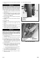
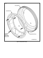
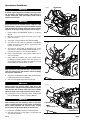
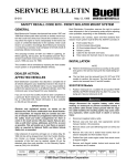
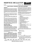
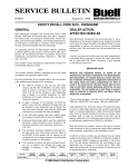
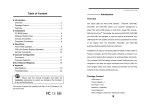
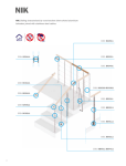
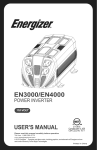
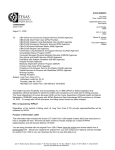
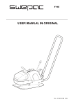
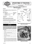
5
SERVICE BULLETIN
B-036
October 23, 2000
SAFETY RECALL CODE 0822 - BLAST REAR SPROCKET
GENERAL
Buell Motorcycle Company has learned that certain 2000
Model Year Buell motorcycles were built with a rear sprocket
that could break. This condition could cause the rider to lose
power, lose control, or be struck by debris. Any of these
occurrences could cause serious injury or death. Accordingly,
Buell Motorcycle Company is voluntarily conducting a recall
campaign to formally recall all potentially affected motorcycles.
Buell Distribution Corporation reserves the right to conduct
wave shipments in lieu of processing orders and/or adjusting
order quantities, depending on the availability of parts.
The Blast Rear Sprocket Recall Kit (Part No. 94019Y) consists of:
●
●
●
●
●
This campaign involves all 2000 P3 Blast model Buell motorcycles manufactured between March 3, 1999 and July 6,
2000.
This condition will be remedied by replacing the rear
sprocket, sprocket cover, drive belt and installing the recalibrator on all potentially affected vehicles.
DEALER ACTION,
AFFECTED VEHICLES
●
●
80 Tooth Rear Sprocket
139 Tooth Drive Belt
Sprocket Cover
(5) Hardened Washers
(5) Bolts
Speedometer Recalibrator
(2) Cable Ties
REPLACEMENT
NOTE
Perform the following procedures according to the guidelines
given in the service manual for the model being serviced.
Drive Belt and Rear Sprocket
Buell Distribution Corporation has attached a complete list of
all vehicles shipped to your dealership involved in this recall. To
ensure the safety of all affected riders, it is your responsibility
to perform the required service on all affected vehicles, even if
the motorcycle was not purchased from your dealership.
If you are not sure that a safety recall has been completed on
a particular Buell motorcycle, contact the recall information
line at 1-800-448-1708. Recall information is also available
on TALON and hd-net.com.
IMPORTANT NOTE
1.
Secure motorcycle on suitable lift that secures the front
wheel.
2.
Remove seat. See appropriate service manual, Section
2 for procedure.
1WARNING
To protect against shock and accidental start-up of vehicle, disconnect the negative battery cable before proceeding. Inadequate safety precautions could result in
death or serious injury.
3.
Disconnect the negative battery cable from the battery.
Because only registered owners, as shown on the
attached list, will receive notification from Buell Distribution Corporation, we request that you contact any owners of vehicles still listed as unregistered. Advise them of
the safety recall and make arrangements for them to
come in for recall service. We also require that you provide us with their names, addresses and V.I.N.s as soon
as possible. This will enable us to mail them an owner’s
letter as required by National Traffic and Motor Vehicle
Safety Act, as amended.
4.
Raise rear wheel off floor using REAR WHEEL SUPPORT STAND (Part No. B-41174).
5.
See Figure 1. Place rod or screwdriver through axle hole.
Loosen rear axle nut (metric).
6.
Remove nut, lockwasher, and flat washer.
7.
Pull axle out. Remove right side spacer.
8.
Slide carrier with caliper off rotor.
9.
Remove left side spacer.
Initial shipment of recall kits will begin on or before October
27, 2000. All kits will be shipped direct from the Franklin Distribution Center, no charge, transportation paid. To order the
remainder of kits that may be needed, please fill out the
attached order form and send/fax it to the Warranty Department at (FAX) 414-343-8346.
10. Move wheel forward, disengage drive belt and remove
rear wheel from motorcycle. Place wheel on clean work
surface, sprocket side up.
ROUTING
SERVICE
MANAGER
SALES
MANAGER
PARTS
MANAGER
LEAD
TECHNICIAN
11. See Figure 2. Remove five sprocket bolts, sprocket cover
and hardened washers from rear wheel. Destroy and discard removed parts.
TECHNICIAN
NO. 1
TECHNICIAN
NO. 2
TECHNICIAN
NO. 3
INITIAL HERE
©2000 Buell Distribution Corporation
TECHNICIAN
NO. 4
RETURN
THIS TO:
12. Remove sprocket from rear wheel. Destroy and discard
sprocket.
29. Lower motorcycle rear wheel.
1WARNING
3
Always wear proper eye protection and gloves when
working with compressed air. Compressed air may eject
debris with enough force to cause injury. Inadequate
safety precautions may result in death or serious injury.
13. Clean residual loctite from threads in wheel sprocket
towers with a suitable non-flammable solvent. Dry with
compressed air.
1
4
14. Remove three TORX bolts, washers and front sprocket
cover from right side of motorcycle. NOTE: It may be
necessary to compress suspension to gain access to
front sprocket cover TORX bolt.
15. Remove two TORX screws and washers from right side
of rear inner fender.
16. Carefully bend rear inner fender upwards and remove
drive belt.
17. Discard drive belt.
1.
2.
3.
4.
2
Axle nut (metric)
Lockwasher
Washer
Axle hole
18. Position new 139-tooth drive belt over transmission drive
sprocket.
19. Install rear inner fender with two TORX screws and
washers.
Figure 1. Rear Sprocket
7701
6
20. Apply LOCTITE THREADLOCKER 243 (Blue) to first few
threads of front sprocket cover TORX screws.
21. Install front sprocket cover with three TORX screws and
washers. Tighten screws to 30-36 in-lbs (3-4 Nm).
4
5
1WARNING
2
Use only new P/N BA0511.2Z hardened washers between
sprocket cover and sprocket. Failure to use hardened
washers could cause sprocket to fail. Drive sprocket failure could lead to loss of control of vehicle which could
result in death or serious injury.
1
6
22. Place sprocket on rear wheel while rear wheel assembly
is lying flat on bench.
23. See Figure 3. Place new hardened washers on sprocket.
24. Install new sprocket cover over washers and sprocket.
25. Install five new sprocket bolts to sprocket, sprocket cover
and rear wheel. Make sure washers are positively
retained by mounting bolts. Tighten sprocket bolts to 2831 ft-lbs (38-42 Nm).
3
7
1.
2.
3.
4.
Axle
Axle nut (metric)
Lockwasher
Washer
5.
6.
7.
Spacer
Sprocket bolts (5)
Sprocket cover
Figure 2. Rear Axle, Right Side
26. Position wheel in mounting position. Slide axle through
washer, swing arm, carrier, left side spacer and wheel
assembly. Position drive belt inboard of sprocket.
a.
See Figure 2. Hold right side spacer in place.
b.
Insert axle through right side spacer and swingarm.
c.
Install flat washer, lockwasher and axle nut.
27. Place screwdriver or rod through axle hole and tighten
rear axle nut to 48-52 ft-lbs (65.1-70.5 Nm).
28. Slide belt on sprocket teeth by rotating rear wheel to
“walk” belt onto teeth.
2 of 5
B-036
a0900x2x
* Rear Sprocket
* Sprocket Cover
* Sprocket
Bolts (5)
28-31 ft-lbs
(38-42 Nm)
* Hardened Washers (5)
* = Included In Kit
Figure 3. Rear Sprocket Assembly
Speedometer Recalibrator
1WARNING
Recalibrator
a0288x7x
To protect against shock and accidental start-up of vehicle, disconnect the negative battery cable before proceeding. Inadequate safety precautions could result in
death or serious injury.
1WARNING
[65A]
[65B]
Always disconnect the negative battery cable first. If the
positive battery should contact ground with the negative
cable installed, the resulting sparks may cause a battery
explosion which could result in death or serious injury.
1.
Remove battery. See BATTERY, Section 7 of Service
Manual.
2.
Disconnect connector [65] located under seat on right
side of motorcycle.
3.
See Figure 4. Plug recalibrator into [65A] and [65B].
4.
See Figure 5. Loop cable over backside of recalibrator
making sure there is some slack in speed sensor wire
harness on sensor end.
5.
See Figure 6. Using cable tie provided in kit, secure
speed sensor connector [65B]/recalibrator bundle to system relay wire harness in front of shock absorber.
6.
Using a long nose pliers, cinch cable tie. Make sure no
wires are pinched.
7.
Using cable tie provided in kit, secure speed sensor/
recalibrator connector [65A] to main wire harness on
right hand side under seat. Make sure cable tie is located
over braided loom and not directly on wires.
Figure 4. Connecting Recalibrator
a0291x7x
CAUTION
Make sure there is adequate free play in positive battery
cable and speed sensor wire harness. Failure to comply
may result in cable failure.
8.
Verify there is adequate free play in both positive battery
cable and speed sensor wire harness.
9.
Tuck connector [65A] under frame on right side.
Figure 5. Looping Wire Harness
1WARNING
a0289x7x
Always connect the positive battery cable first. If the
positive battery should contact ground with the negative
cable installed, the resulting sparks may cause a battery
explosion which could result in death or serious injury.
10. Install battery and connect battery cables, positive cable
first. See BATTERY, Section 7 of Service Manual.
1WARNING
After installing seat, pull upward on front of seat to be
sure it is locked in position. If seat is loose, it could shift
during vehicle operation and startle the rider, causing
loss of control of vehicle and death or serious injury.
11. Install seat. See SEAT, Section 2 of Service Manual.
12. Test ride motorcycle to verify proper rear sprocket and
speedometer operation.
4 of 5
* Recalibrator
* Cable TIes (2)
System Relay
* = Included in Kit
Figure 6. Securing Wire Harnesses
B-036
CREDIT PROCEDURES VEHICLE REPAIR
CREDIT PROCEDURES DEALER STOCK PARTS
For each vehicle serviced, place a “C” in the letter box on the
Buell Dealer Service Card. Send the properly completed
dealer service cards to Buell Distribution Corporation, 3700
W. Juneau Ave., Milwaukee, WI 53208. Upon receipt and processing of your properly completed dealer service cards, you
will be credited for 1.9 hours for labor for Domestic vehicle
repair and 2.0 hours labor for Canadian vehicle repair. Time
includes appropriate administrative time and LOCTITE products. No credit will be issued for the kits as they were sent no
charge, transportation paid.
Remove all affected sprockets, sprocket covers and drive
belts (Part Nos. listed below) from your inventory. To receive
credit, complete a regular warranty claim referencing Service
Bulletin B-036 in the “Description of Repair” section. Fill in the
rest of the claim as follows.
Table 1. Credit for Parts
Claim Type
Quantity
BDS
See Note Below
Event 1,
Problem Part No.
G0400.T
Part Description
Rear Sprocket
Event 2,
Problem Part No.
G0556.T
Part Description
Sprocket Cover
Event 4,
Problem Part No.
G0500.T
Part Description
135-Tooth Drive Belt
Customer Concern
Code
9205
Condition Code
9111
NOTE
“Quantity” may vary depending upon what you have in stock.
Upon receipt of properly completed claim for parts in dealer
stock, you will receive the appropriate credit for parts. Buell
Distribution Corporation advises ordering standard 2001
Model Year belts, rear sprockets and sprocket covers to
replenish your stock. Do not order the recall kits to restock
your inventory!
B-036
5 of 5
BUELL DISTRIBUTION CORPORATION
TYPE
CODE
R
P
P.O. BOX 594, MILWAUKEE, WI U.S.A 53201
PARTS & ACCESSORY ORDER
D
W
B-036
ORDER TYPE
REGULAR
POLICE
DOWN VEHICLE
WARRANTY
DEALER
ORDER
VEHICLE
IDENTIFICATION
NUMBER
ORDER
DATE
DEALER
NO.
ORDER
TYPE
D-W
WARRANTY CLAIM NO.
S
O
L
D
T
O
S
H
I
P
NAME
ADDRESS
T
O
CITY/STATE/ZIP
QUANTITY
NAME
ADDRESS
FOR OFFICE USE ONLY
SAME
ACCT.
FRT.
ACCT.
CITY/STATE/ZIP
111-632.5
111-632.5
PART NUMBER
94019Y
Code 0822: BLAST REAR SPROCKET KIT
NOTE: All orders subject to approval. You may not receive the total quantity of
kits ordered, due to parts a availability. If this happens, please submit another
ordered for the balance.
822
0
DE
O
C
Y
T
N
A
R
R
WA
PLEASE USE PART NUMBERS
DO NOT USE FOR
CORRESPONDENCE
F-1040
PLEASE USE PART NUMBERS
DO NOT USE FOR
CORRESPONDENCE
ALL ORDERS SUBJECT TO ACCEPTANCE AT MILWAUKEE, WI 53201
All goods covered by this order, including goods back-ordered, will be billed at prices current at the time of shipment. Goods are purchased for resale and delivery is made to purchaser F.O.B. factory, Milwaukee,
Wisconsin or other point of origin. If accepted, this order as accepted shall be subject to availability of goods to seller for delivery to purchaser. Any delay in shipment shall not relieve purchaser of responsibility for his
accepted order and seller shall not be liable for any loss or damage due to delay in shipment or failure to deliver. Any request for cancellation of this order or any part thereof must be received by seller prior to the date
of shipment, and in case of reconsignment or return of goods to seller, purchaser shall pay the entire cost connected therewith, plus zero, ten or twenty-five percent of selling price, as determined by Company policy
from time to time, as liquidated damages for loss of sale. Purchaser will be responsible for collection and payment of all Federal, State and local taxes that apply on the retail sales.
PRINTED
IN U.S.A