1
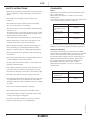
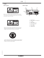
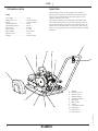
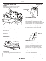
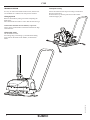
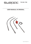
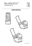
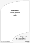
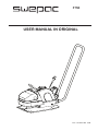
F75E
USER MANUAL IN ORIGINAL
Doc: 101491A-GB 1308
Doc: 101491A-GB 1308
F75E
F 50
2
F75E F 50
USE
SWEPAC F75E
is used to pack gravel and sand in connection with minor
construction work such as the basis for concrete blocks or
paving stones for gardens. The machine’s compact design
ensures good accessibility in tight spaces.
CONTENTS
Doc: 101491A-GB 1308
USE........................................................................... 3
SAFETY INSTRUCTIONS...................................... 4
STANDARDS........................................................... 4
SIGNS....................................................................... 5
TECHNICAL DATA................................................. 6
FUNCTION.............................................................. 6
TECHNICAL DESCRIPTION................................. 6
V-BELT DRIVE ..................................................... 7
POLYURETAN PAD................................................7
OPERATING INSTRUCTIONS.............................. 7
IMPORTANT............................................................ 7
TRANSPORTATIONS............................................. 8
EC-DECLARATION OF CONFORMITY............... 9
3
F75E
F 50
SAFETY INSTRUCTIONS
• Before using the machine, the operator must be informed
of the manufacturer’s safety instructions and instructions
for use.
• The machine is intended for use both indoors and
outdoors.
• The machine may not be used if protection and safety
devices are not present or not working.
• The operator may not leave the machine unattended when
the motor is on.
When the vibrator is connected, the operator must be able
to control the movement of the machine using the control
handle and the start/stop controls.
The machine may be operated only by a trained operator.
• During maintenance work or other interventions in the
machine, the electricity must be disconnected.
• Before lifting the machine, check that the lifting device
and its mounting are not damaged and that the rubber
dampers on the base plate are undamaged and tightened.
• The operator must use ear protectors when working with
the machine.
• The operator must ensure that no unauthorized persons are
in the immediate vicinity of the machine.
• Protect yourself from electric shocks. Avoid contact with
lightning conductors/metal.
STANDARDS
Noise
Measurement in accordance with the standard EN 500-4
Rev. 1:1998, Annex C:
Measurement uncertainty ± 0.5 dB (A) in 95% of the
measurements.
In accordance with the conditions in Directive 2000/14/EC,
Annex VI, the following values are reported:
Sound pressure level
at the operator’s ears, LpA
90 dB (A)
Permitted sound
power level, L WA
105 dB (A)
Guaranteed sound
power level, L WA
103 dB (A)
As the sound pressure level at the operator’s ears exceeds
80 dB (A), ear protectors must be used during operation!
Hand/arm vibrations
The vibration acceleration was measured in accordance
with the ISO 5349 standard during operation on a graveled
surface. The measurement values were translated into
the maximum daily exposure time for regular usage. For
additional information about vibrations, please confer
the regulation AFS 2005:15 from the Swedish Work
Environment Authority, effective July 1st 2005.
Measurement uncertainty ± 0.3 m/s2 in 95% of the
measurements
• Never pull the machine by means of the cable and never
pull on the cable to disconnect the plug. Keep all cables
and extension cables away from water, oil and sharp edges.
• Ensure that the cable does not get caught in fences etc.
• Check that the cable and the extension cable are intact and
in good condition. Never use the machine if the cable is
damaged, rather put it into an authorised service workshop
for repair.
Hand/armvibrations, m/s2
The maximum daily
exposure time
4,6
2,4 h
• Never use an extension cable that is rolled up.
• The machine must be connected to an earthed socket.
• Check that the mains voltage corresponds with the rated
voltage on the engine’s rating plate.
Doc: 101491A-GB 1308
• Ensure that the cable is behind you when you start the
machine so that there is no risk of damaging it.
4
F75E
F 50
SIGNS
Warning signs
Machine Signs
1
2
3
9
8
4
MACHINERY
5
Before use, carefully read the manual and its safety instructions so that you can handle the machine safely. Ensure that
the manual is always accessible.
7
1.
2.
3.
4.
5.
6.
7.
8.
9.
6
Manufacturer
Place, country of manufacture.
CE mark.
Model name.
Year of manufacture.
Max. engine power.
Max. weight.
Serial number.
Machine type
Belt drive: Keep hands, tools and other objects away from
the belt drive when the machine is on to avoid injury and
damage. See the safety instructions in the manual.
Doc: 101491A-GB 1308
As the sound pressure level at the operator’s ears exceeds 80
dB (A), ear protectors must be used when working with the
machine to prevent hearing damage.
5
F75E
F 50
TECHNICAL DATA
FUNCTION
The machine consists of a base plate with a vibration
element and an upper part cushioned from the base plate.
The power is transmitted from the petrol engine to the
vibration element via a V-belt.
The engine is fitted with an integrated centrifugal clutch.
On account of the direction of rotation and the position of
the vibration element at the front end of the base plate, the
vibrator moves forward under its own power. The moving
parts are well protected by a cover made of impact resistant
polythene.
F75E
Net weight..................................75 kg
Base plate, w x l.........................380 x 530 mm
Speed..........................................appr 25 m/min
Centrifugal force........................11 kN
Vibration frequency...................88 Hz
Drive motor................................Electric
Motor power...............................1,1 kW
Motor RPM................................2810 r/min
Rated current..............................6,45A
Voltage.......................................230V 1-phase
1
10
11
5
8
12
3
2
7
9
4
Doc: 101491A-GB 1308
6
1. Handle
2. Protective cover
3. Electric motor
4. Rubber damper
5. Vibration element
6. Base plate
7. Motor plate
8. V-belt
9. Centrifugal clutch
10. Lifting eye
11. Start switch
12. Strain relief
6
F75E
F 50
TECHNICAL DESCRIPTION
Stopp button (red)
V-belt Drive
Check the tension and condition of the V-belt regularly.
Replace a damaged V-belt with the new type A30.
Start button (red)
Circuit breaker
4
1
2
Adjustment of V-belt tension
Loosen the screws (1, 4 pcs) that hold the engine plate.
Loosen the screws (2, 3 pcs) holding the cover.
Remove the cover.
3
OPERATING INSTRUCTIONS
The machine’s vibration element is started by means of the
green start button on the start switch. Thanks to its compact
design and low weight, the machine’s is very easy to
manoeuvre. The design of the base plate allows the machine
to be pulled backwards without disturbing the packed
surface. The machine’s vibration element stops when the red
stop button on the start switch is pressed. The machine is
intended for use both indoors and outdoors. Work with the
machine in daylight or other adequate lighting.
Ballast must be wetted or naturally damp. When operating
the machine secure the electric cable in the strain relief as in
the illustration below. All other use is discouraged.
Tension the V-belt by pulling the handle (3).
Tighten the screws.
Refit the cover.
Strain relief
Rubber Dampers
Check the condition of the rubber dampers (4, 4 pcs)
regularly. Replace damaged dampers.
Electric cable
IMPORTANT
It is important to consider the following when using
Swepac F75E in single phase version.
Doc: 101491A-GB 1308
In some adverse cases, the machine can consume so
much power in the moment of starting that the circuit
breaker is triggered. Wait 1 minute before resetting.
Low voltage supply to the machine can lead to inferior
performance (lower rotation speed and torque).
Polyuretan Pad
A polyuretan pad is used for stone paving work to protect
against stones and ground clinker.
Among other things, low voltage to the machine can be
due to:
- Low incoming voltage (under 230V)
- Use of cables that are too delicate (at least 2.5 sq mm
conductors are recommended).
- Use of a cable that is longer than 20 m.
7
F75E
F 50
TRANSPORTATION
Transport locking
It is easy to remove the handle without tools, and the boot
of a standard car is sufficient to transport the machine.
Secure the machine with straps according to illustration
during transportation
Note! Secure it by the base plate and not the rubbercushioned upper part.
Lifting by hand
Remove the handle by tilting it forward and pulling the
shafts apart.
Move the handle from side to side so that the dowels let go.
Caution!The machine must be lifted by 2 persons!
Lift by means of the handle on the back and the front edge
of the machine.
Doc: 101491A-GB 1308
Lifting with crane
Tilt the handle forward.
Fit a lifting sling to the lifting eye and thread the lifting
sling between the shafts of the handle, see illustration
below.
8
F75E
F 50
EC-declaration of conformity
Manufacturer
Swepac AB
Blockvägen 3
34132 Ljungby
1. Category: Vibratory plate
2. Type: F75E
3. Motor power: 1,1kW
The product complies with the following directives:
2006 / 42 / EG
2004 / 14 / EG
2000 / 108 / EG
EN500-1
EN500-4
2006 / 95 / EG
Technical documentation held by:
Doc: 101491A-GB 1308
Swepac AB, Blockvägen 3 34132 Ljungby SE
Tomas Johansson / Product Engineer
9
Doc: 101491A-GB 1308
F75E
F 50
10
Doc: 101491A-GB 1308
F75E
F 50
11
SWEPAC AB
Address Blockvägen 3, 341 32 Ljungby, Sweden, tel. +46 (0)372-156 00, fax +46 (0)372-837 41, E-mail [email protected],
Internet www.swepac.se