1
Service Manual
ZIRCONIA OXYGEN
ANALYZER CONVERTER
transmission specification
(MODBUS)
TYPE: ZKM
INZ-TN5A0506a-E
CONTENTS
1.
COMMUNICATION FUNCTION.................................................................................................. 1
1.1
2.
SPECIFICATIONS .......................................................................................................................... 2
2.1
3.
Outline.....................................................................................................................................................7
Composition of Message.........................................................................................................................8
Response of Slave Station.......................................................................................................................9
Function Code.......................................................................................................................................10
Calculation of Error Check Code (CRC-16).........................................................................................11
Transmission Control Procedure...........................................................................................................13
DETAILS OF MESSAGE ............................................................................................................. 15
6.1
6.2
6.3
6.4
7.
Setting item .............................................................................................................................................6
Setting operation .....................................................................................................................................6
MODBUS COMMUNICATION PROTOCOL............................................................................... 7
5.1
5.2
5.3
5.4
5.5
5.6
6.
Setting of jumper pin ..............................................................................................................................3
Terminal allocation (TM2)......................................................................................................................3
Connection ..............................................................................................................................................4
SETTING OF COMMUNICATION CONDITION ........................................................................ 6
4.1
4.2
5.
Communication specifications................................................................................................................2
CONNECTION................................................................................................................................ 3
3.1
3.2
3.3
4.
Outline.....................................................................................................................................................1
Word data readout [Function code: 03H]...............................................................................................15
Reading Read-Only Word Data [Function Code: 04H] .........................................................................16
Writing Word Data (unit of 1word) [function code: 06H] .....................................................................17
Writing Continuous Word Data [Function code: 10H] ..........................................................................18
ADDRESS MAP AND DATA FORMAT .................................................................................... 19
7.1
Data format ...........................................................................................................................................19
7.1.1 Transmission data format............................................................................................................19
7.1.2 Handling of decimal point position and measurement unit ........................................................19
7.1.3 Handling at measurement data over-range..................................................................................19
7.2 Address map..........................................................................................................................................20
INZ-TN5A0506-E
i
1. COMMUNICATION FUNCTION
1.1 Outline
• This instrument provides a communication function through RS232-C and RS-485 which allows data
transmit to or receive from the host computer and other devices.
• The communication system is composed of a master and slave relationship.
Up to 31 of slave station (present instrument) can be connected per master station (host computer,
programmable controller, graphic display panel, etc.) through RS485 interface.
One slave station (this instrument) can be connected to one master station.
• Because the master station can communicate with only one slave station at a time, the destination can be
identified by the “Station No.” set for each slave station.
• In order that the master station and slave station can communicate, the format of the transmit/receive data
must coincide. For the PXR, the format of the communication data is determined by the MODBUS
protocol.
INZ-TN5A0506-E
1
2. SPECIFICATIONS
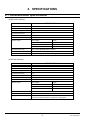
2.1 Communication specifications
(a) RS-232C Interface
Item
Electrical specification
Communication method
Synchronizing method
Connection format
Number connectable units
Baud rate
Data Format
Transmission code
Error detection
Isolation
SPECIFICATIONS
Communication standard: RS-232C
2-wire, semi-duplicate
Start-stop synchronous system
1:1
1 unit
38400 bps
Data length
8 bits
Stop bit
1 bits
Parity
None
X flow control
None
HEX value (MODBUS RTU mode)
CRC-16
Not isolated against communication part and other parts.
(b) RS-485 interface
Item
Electrical specification
Communication method
Synchronizing method
Connection format
Number connectable units
Communication distance
Baud rate
Data Format
Transmission code
Error detection
Isolation
SPECIFICATIONS
Based on EIA RS-485
2-wire, semi-duplicate
Start-stop synchronous system
1:N
31 units
Maximum 500m (total extansion)
38400 bps
Data length
8 bits
Stop bit
1 bits
Parity
None
X flow control
None
HEX value (MODBUS RTU mode)
CRC-16
Isolation from internal circuit
Functional isolation between signal line and ground
2
INZ-TN5A0506-E
3. CONNECTION
WARNING
Do not turn on the power supply until all wiring have been completed to avoid electric shock
and malfunctions.
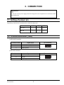
3.1 Setting of jumper pin
Depending on the kind of communication, switch the jumper pin.
Communication
RS 232C
RS 485
JP1
JP2
3-5
4-6
1-3
2-4
3-5
4-6
1-3
2-4
JP5
2-3
1-2
3.2 Terminal allocation (TM2)
(a) RS-232C Interface
Terminal number
1
2
3
Signal name
Transmission data (TXD)
Receive Data (RXD)
Signal ground
Pin connection
1
2
3
(b) RS-485 Interface
Terminal number
1
2
3
INZ-TN5A0506-E
Signal name
RTxD+
RTxDSingnal ground
Pin connection
1
3
2
3
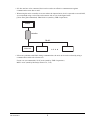
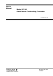
3.3 Connection
(a) RS-232C Interface
Master
RXD
Twisted pair cable
with shield
Slave (ZKM)
TXD
TXD
RXD
SG
SG
FG
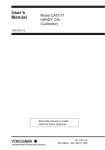
(b) RS-485 interface
• Please use a shielded twist pair cable.
(Recommended cable: KPEV-SB (made by The Furukawa Electric Co., Ltd.))
• The total extension length of the cable is up to 500 m. One master and up to thirty-one micro
controllers (slaves) can be connected per circuit.
• Both ends of the cable should be terminate with terminating resistors 100Ω (1/2W or more).
• Ground the shielded cable once towards the master side.
4
INZ-TN5A0506-E
• SG does not have to be connected, but it can be used as an effective countermeasure against
communication errors due to noise.
• When using the micro controller in an area where the imposed noise level is expected to exceed 500V,
we recommend using a noise filter on the master side as seen in the figure below.
[Noise filter] (Recommended): ZRAC2203-11 (made by TDK Corporation)
Master
Noise filter
RS-485
Main unit
• If there are problems with EMC during communication, the noise level can be reduced by using a
communication cable with a ferrite core.
Ferrite core (recommended): ZCAT series (made by TDK Corporation)
MSFC series (made by Morimiya Electric Co., Ltd.)
INZ-TN5A0506-E
5
4. SETTING OF COMMUNICATION CONDITION
In order that the master station and instrument (this instrument) can correctly communicate, following settings
are required.
• All communication condition settings of the master station are the same as those of instruments (this
instrument).
• All instruments (this instrument) connected on a line are set to “Station No.” which are different from each
other. (Any “Station No.” is not shared by more than one instrument.)
4.1 Setting item
The parameters to be set are shown in the following table.
Set them by operating keys on the screen.
Item
Factory shipment
default
Baud rate
Data length
Stop bit
Parity setting
38400 bps
8 bits
1 bits
None
Station No.
1
Settable range
Fixed (can not be changed)
Fixed (can not be changed)
Fixed (can not be changed)
Fixed (can not be changed)
0 to 31
(0: Communication function stops )
Remarks
Set the same communication
condition to the master station
and all slave stations.
Set a different value to each
station.
4.2 Setting operation
Set the station No. on the parameter screen. (Refer to the instruction manual)
6
INZ-TN5A0506-E
5. MODBUS COMMUNICATION PROTOCOL
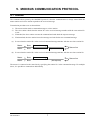
5.1 Outline
The communication system by the MODBUS protocol is that the communication is always started from the
master station and a slave station responds to the received message.
Transmission procedures are as shown below.
1) The master station sends a command message to a slave station.
2) The slave station checks that the station No. in the received message matches with the own station No.
or not.
3) If matched, the slave station executes the command and sends back the response message.
4) If mismatched, the slave station leaves the message and wait for the next command message.
(a) In case when the station No. in the received command message matches with the own slave station No.
Master
Slave
Master
Slave
Command message
Data on line
Response message
(b) In case when the station No. in the received command message matches with the own slave station No.
Master
Slave
Master
Slave
Command message
Data on line
(No response)
The master is connected to the same line by specifying the station No. in the command message. For multiple
slaves, it is possible to communicate individually.
INZ-TN5A0506-E
7
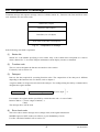
5.2 Composition of Message
Command message and response message consist of 4 fields; Station No., Function code, Data and Error check
code. And these are sent in this order.
Station No. (1 Byte)
Function Code (1 Byte)
Data Part (2 to 133 Bytes)
Error check code (CRC-16) (2 Bytes)
Fig. 5-1
Composition of message
In the following, each field is explained.
(1)
Station No.
Station No. is the number specifying a slave station. Only a slave station that corresponds to a value to
which “Station No.” is set on the analyzer maintenance mode display executes a command.
(2)
Function code
This is a code to designate the function executed at a slave station.
For details, refer to section 5.4.
(3)
Data part
Data are the data required for executing function codes. The composition of the data part is different
depending on the function code. For details, refer to chapter 6.
A register number is assigned to each data in the analyzer. For reading/writing the data by communication,
designate the register number.
Relative address = Coil number or register number of last 4 digits. – 1
For example, the register number specified by certain function code = in case of 4003
Relative address = (Lower 4 digits of 40003) – 1
= 0002
The message above will be used.
(4)
Error check code
This is the code to detect message errors (change in bit) in the signal transmission.
MODBUS protocol (RTU mode) uses CRC16 (Cyclic Redundancy Check).
For CRC calculation method, refer to section 5.5.
8
INZ-TN5A0506-E
5.3 Response of Slave Station
(1)
Response for normal command
To a relevant message, the slave station creates and sends back a response message which corresponds to
the command message. The composition of message in this case is the same as in Section 5.2.
Contents of the data field depend on the function code. For details, refer to chapter 6.
(2)
Response for abnormal command
If there are problems (such as specification of a nonexistent function code) with the contents of the
command message other than transmission error, the slave creates and replies with an error response
message without following the command.
The composition of response message at error detection is as shown in Fig. 5-2 the value used for function
code field is function code of command message plus 80H.
Table 5-1 gives error codes.
Station No. (1 byte)
Function code + 80H (1 byte)
Error code (1 byte)
Error check code (CRC-16) (2 bytes)
Fig. 5-2
Response message at error detection
Table 5-1 Error Code
Error code
Contents
01H
Illegal function code
02H
Faulty address for coil or register
03H
Illegal data value
(3)
Explanation
Non-actual function code is designated.
Check for the function code.
A relative address of a coil number or resister
number to which the designated function
code can not be used.
Because the designation of number is too
much, the area where resister numbers do not
exist is designated.
No response
Under any of the following items, the slave station takes no action of the command message and sends
back no response.
• A station number transmitted in the command message differs from the station number specified to
the slave station.
• An error check code is not matched, or a transmission error (parity error, etc.) is detected.
• The time interval between the composition data of the message becomes longer than the time
corresponding to 24 bits. (Refer to Section 5.6 Transmission Control Procedure)
INZ-TN5A0506-E
9
5.4 Function Code
According to MODBUS protocol, register numbers are assigned by function codes. Each function code acts on
specific register number.
This correspondence is shown in Table 5-2, and the message length by function is shown in Table 5-3.
Table 5-2 Correspondence between function codes and objective address
No.
03H
04H
06H
10H
Function Code
Function
Remedy
reading (continuance) Holding register
reading (continuance) Input register
Writing
Holding register
Writing (continuance) Holding register
No.
4xxxx
3xxxx
4xxxx
4xxxx
Register No.
Contents
Reading/writing Word data
Reading
Word data
Reading/writing Word data
Reading/writing Word data
Table 5-3 Function code and message length
Function Code
03H
04H
06H
10H
Contents
Read word data
Read word (Read only)
Write word data
Write continuous word data
Designated
data
64 words
64 words
1 word
64 words
10
Command
message
Mini.
Max.
8
8
8
8
8
8
11
137
[UNIT: byte]
Response
message
Mini.
Max.
7
133
7
133
8
8
8
8
INZ-TN5A0506-E
5.5 Calculation of Error Check Code (CRC-16)
CRC-16 is the 2-byte (16-bits) error check code. From the top of the message (station No.) to the end of the
data field are calculated.
The slave calculates the CRC of the received message and ignores the message if this value is not the same as
the received CRC code.
The following shows the calculation procedure for CRC-16.
(a) Store FFFFH into 16 bits register (CRC register)
(b) Subject the 1st byte (8 bits) of transmit message and CRC register contents to an exclusive logical
summation (XOR), and store the result into the CRC register.
(c) Shift the CRC register contents 1 bit to the right. Store 0 at MSB.
(d) If LSB before shifting is 0, do nothing.
If LSB before shifting is 1, subject it and A001H to XOR, and store the result into the CRC register.
(e) Repeat the steps (c) and (d) 8 times (shift by 8 bits).
(f) Execute steps (b) to (e) for the next byte of the transmit message.
Likewise, successively repeat the steps to each byte of the transmit message.
(g) The CRC code that is retained is the value of CRC register that stands when the processing has ended
for latest byte (latest data except error code) of the transmit message.
(h) As error check code of the transmit message, store this CRC value in the order of lower 8 bits and upper
8 bits.
Transmit message (ex.)
01H
06H
00H
05H
03H
E8H
99H
75H
Calculate the date between these
numbers in order, figure out CRC.
In this case, CRC=75 99H
Attach the error check code to
message upon interchanging the
upper CRC and lower orders.
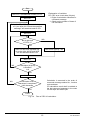
Fig. 5-3 Shows the flow of the CRC-16 calculation system.
INZ-TN5A0506-E
11
Start
Set FFFFH (hexadecimal number) in CR.
Set 1 to I
*Explanation of variables
CR : CRC error check data (2 bytes)
I : Digits of calculation characters in
command message
J : Check on the number of times of
CR calculation
Exclusive-OR (XOR) runs on each character
of J (one byte) for CR and the specified
message, and sets that result to CR.
Set 1 to J
NO
Bit at right end
of CR is 1?
YES
Shift CR to right by 1 bit.
After CR has been adjusted one
bit to the right, A001H and XOR
run and set that result to CR.
Add 1 to J
NO
Calculation (8 times)
is finished?
J>8
YES
Add 1 to I
NO
Calculation is executed in the order of
command message station No., function
code and data.
CR calculation result shall be added to
the last command message in the order
of LOW byte and HIGH byte.
Calculation of all
characters is completed?
I>All characters
YES
Close
Fig. 5-4
Flow of CRC-16 calculation
12
INZ-TN5A0506-E
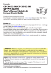
5.6 Transmission Control Procedure
(1)
Transmission procedure of master station
The master station must proceed to a communication upon conforming to the following items.
(1-1) The command message, must be sent after an empty space of at least 48 bit time.
(1-2) Interval between bytes of 1 command message is smaller than 24 bits time.
(1-3) After sending a command message, for less than 24 bit time the master will enter receiving
standby.
(1-4) After receiving the response message, the next command message must be sent after at least 48
bit time. [Same as in (1-1)]
(1-5) For safety reasons, create a framework where the master checks the response message, and if
there is no response or an error occurs, retry at least three times.
Note) The definitions written above are for the minimum required value. For safety reasons, we
recommend creating a master side program that keeps margins two to three times as large.
Concretely, it is advised to arrange the program for 38400 bps with 5ms or more for vacant statues
(1-1), and within 1ms for byte interval (1-2) and changeover from sending to receiving (1-3).
INZ-TN5A0506-E
13
(2)
Explanation
1)
Frame detection
The status on the line of the communication system is one of the 2 below.
(a) Vacant status (no data on line)
(b) Communication status (data is existing)
The units connected on the circuit start in receiving state and monitor the circuit. When a blank state
appears on the circuit for at least 24 bit time, the unit detects the end of the previous frame, and within
the next 24 bit time, enters receiving standby. When data appears on the circuit, the unit begins
receiving data, and once another blank state of at least 24 bit time is detected, that frame is ended. In
other words, the data on the circuit from the first time that a 24 bit time blank state appears to the
second time one appears is loaded as one frame (a bundle of data).
Therefore, one frame (command message) must be sent while following the rules below.
(1-1) The command message must be sent after an empty space of at least 48 bit time.
(1-2) Interval between bytes of 1 command message is smaller than 24 bits time.
2)
Response of this instrument
After the PUM detects the frame (detects blank states at least 24 bit times long), that frame is used to
send a command message. If the command message is destined to the own station, a response message
is returned. Its processing time is 1 to 30 ms (The time may change depending on the contents of the
command message.)
Therefore, one frame (command message) must be sent while following the rules below.
(1-3) After sending a command message, for less than 24 bit time the master will enter receiving
standby.
Space time of longer than 25 ms
is needed.
(5ms or more is recommendable)
Control
Station → Main unit
POL1
POL2
1 to 30msec
Control
Station ← Main unit
POL1 Response data
Data on line
POL1
POL1 Response data
14
POL2
INZ-TN5A0506-E
6. DETAILS OF MESSAGE
6.1 Word data readout [Function code: 03H]
Function code
03H
(1)
Max. number of words
to read in one message
64 words
Relative address
{Register No.
0000 to 0081
40001 to 40082
Contents
Setting data
Composition of Message
Command message composition (byte)
Response message composition (byte)
Station No.
Station No.
Function code
Function code
Readout byte number
Readout word number × 2
Readout start number Upper
(Relative address) Lower
Contents of the first Upper
word data
Upper
Lower
1 to 60
Readout Word number
Lower
Contents of the next Upper
word data
Upper
Lower
CRC data
~
~
Lower
Contents of the last Upper
word data
Lower
Upper
CRC data
Lower
Arrangement of read-out word data
MSB
LSB
Upper byte of contents of the first word data
Lower byte of contents of the first word data
Upper byte of contents of the next word data
Lower byte of contents of the next word data
~
~
Upper byte of contents of the last word data
Lower byte of contents of the last word data
(2)
Explanation of Function
Word data of continuous word numbers from the read-out start No. can be read. Read-out word data are
transmitted from the slave station in the order of upper and lower bytes.
INZ-TN5A0506-E
15
6.2 Reading Read-Only Word Data [Function Code: 04H]
Function code
04H
(1)
Max. number of words
to read in one message
Relative address
{Register No.
64 words
0000 to 0081
1000 to 1049
2000 to 2049
3000 to 3049
30001 to 30079
31001 to 31044
32001 to 32044
33001 to 33044
Contents
Internal data
Error history data
Alarm history data
Operation history data
Composition of message
Command message composition (byte)
Response message composition (byte)
Station No.
Station No.
Function code
Function code
Readout byte number
Readout word number × 2
Readout start number Upper
(Relative address) Lower
Contents of the first Upper
word data
Upper
Lower
1 to 60
Readout Word number
Lower
Contents of the next Upper
word data
Upper
Lower
CRC data
~
~
Lower
Contents of the last Upper
word data
Lower
Upper
CRC data
Lower
Arrangement of read-out word data
MSB
LSB
Upper byte of contents of the first word data
Lower byte of contents of the first word data
Upper byte of contents of the next word data
Lower byte of contents of the next word data
~
~
Upper byte of contents of the last word data
Lower byte of contents of the last word data
(2)
Description of functions
Word data of continuous word numbers from the read-out start No. can be read. Read-out word data are
transmitted from the slave station in the order of upper and lower bytes.
16
INZ-TN5A0506-E
6.3 Writing Word Data (unit of 1word) [function code: 06H]
Function code
06H
(1)
Max. number of words
to read in one message
1 words
Relative address
{Register No.
0000 to 0081
40001 to 40082
Setting data
Composition of message
Command message composition (byte)
Station No.
Function code
Write in designation Upper
No. (Relative address) Lower
Upper
Write in word data
Lower
Upper
CRC data
Lower
(2)
Contents
Response message composition (byte)
Station No.
Function code
Write in designation Upper
No. (Relative address) Lower
Upper
Write in word data
Lower
Upper
CRC data
Lower
Description of function
Designated word data is written in write-in designate No. The master sends the data to be written from
the upper number of bytes to the lower number.
INZ-TN5A0506-E
17
6.4 Writing Continuous Word Data [Function code: 10H]
Function code
10H
(1)
Max. number of words
to read in one message
64 words
Relative address
{Register No.
0000 to 0081
40001 to 40082
Contents
Setting data
Composition of message
Command message composition (byte)
Station No.
Function code
Upper
Write in start No.
(Relative address) Lower
Upper
Write in word
1 to 60
number
Lower
Response message composition (byte)
Station No.
Function code
Write in start number Upper
(Relative address ) Lower
Upper
Write in word
number
Lower
Upper
Write in word number × 2
CRC data
Lower
Write in byte number
First write in word
data
Next write in word
data
Upper
Lower
Upper
Lower
~
~
Last write in word
data
CRC data
Upper
Lower
Upper
Lower
Arrangement of write in word data
MSB
LSB
Upper byte of contents of the first word data
Lower byte of contents of the first word data
Upper byte of contents of the next word data
Lower byte of contents of the next word data
~
~
Upper byte of contents of the last word data
Lower byte of contents of the last word data
(2)
Description of functions
Word data of continuous word number is written from write-in start address. The master sends the data
to be written from the upper number of bytes to the lower number.
18
INZ-TN5A0506-E
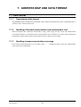
7. ADDRESS MAP AND DATA FORMAT
7.1 Data format
7.1.1
Transmission data format
The MODBUS protocol used in this instrument is RTU (Remote Terminal Unit) mode. Transmitted data is
“numeric value” and not ASCII code.
7.1.2
Handling of decimal point position and measurement unit
When transmitted, the calibration concentration setting, alarm's high and low limits and measurement
concentration data have no decimal point nor measurement unit. Calculate exact values of data upon point
positioning as shown below. Refer to the contents of each “read out/ write in data”.
7.1.3
Handling at measurement data over-range
Even if the measurement data is at over-range, with “ ” displayed on the screen, the measurement
value at the time is transmitted.
INZ-TN5A0506-E
19
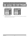
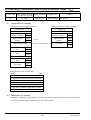
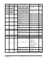
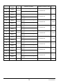
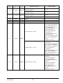
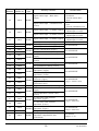
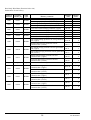
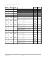
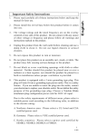
7.2 Address map
Word data [read-out/write-in]: Function code [03H, 06H, 10H]
Relative Registrarion
adderess
number
Data
type
Memory contents
0
40001
Unit {Upper}
WORD Decimal point position of range
{Lower}
1
40002
WORD Range
2
40003
Unit {Upper}
WORD Decimal position of range
{Lower}
3
40004
WORD Range
4
40005
WORD
5
40006
WORD
6
40007
WORD
7
8
9
10
40008
40009
40010
WORD
WORD
WORD
40011
DWORD
11
40012
12
40013
DWORD
13
40014
Read out /weite in data
0: vol%
0: <0.000>
1: <00.00>
0 to 9999
(When the decimal point
position “00.00” is 0200 to
5000, when “0.000” is 2000
to 9999)
0: vol%
0: <0.000>
1: <00.00>
0 to 9999
(When the decimal point
position “00.00” is 0200 to
5000, when “0.000” is 2000
to 9999)
Max.value/Mini.value calculation
0 to 240
time [time]
2 bits: Inhabitation of all
Setting flag
calibration (0: enable, 1:
unenable)
Year of automatic calibration star
00 to 99
{Upper}
Month of automatic calibration
1 to 12
start {Lower}
Date of automatic calibration
1 to 31
start {Upper}
Time of automatic calibration
0 to 23
start{Lower}
Minute of automatic calibration
0 to 59
start {Upper}
Unused
0
Auto calibration cycle (Date)
0 to 99
{Upper}
Auto calibration cycle (Time)
0 to 99
{Lower}
Calibration span gas
concentration {Upper} (Range 1) 00010 to 50000
(1 digit = 0.001 vol%)
Calibration span gas
concentration {Lower} (Range 1)
Calibration span gas
concentration {Upper} (Range 1) 00010 to 25000
(1 digit = 0.001 vol%)
Calibration zero gas
concentration {Lower} (Range 1)
20
Default
value
0
1
2500
0
1
2500
24
0
99
1
1
0
0
0
7
0
206000
20000
INZ-TN5A0506-E
Relative Registrarion
adderess
number
14
Data
type
40015
DWORD
15
40016
16
40017
DWORD
17
40018
18
40019
19
20
21
22
23
40020
40021
40022
40023
40024
WORD
WORD
WORD
WORD
WORD
WORD
24
40025
WORD
25
40026
WORD
26
40027
WORD
Memory contents
Calibration span gas
concentration {Upper} (Range 2)
Calibration span gas
concentration {Lower} (Range 2)
Calibration zero gas
concentration {Upper} (Range 2)
Calibration zero gas
concentration {Lower} (Range 2)
Year of automatic blow back start
{Upper}
Month of automatic blow back
start {Lower}
Date of automatic blow back start
{Upper}
Time of automatic blow back
start {Lower}
Minute of automatic blow back
start {Upper}
Unused
Automatic blow cycle (time)
{Upper}
Automatic blow cycle (minute)
{Lower}
Blow time [second]
Sensor diagnostic execution flag
during calibration {Upper}
restored sensor execution
processing flag during calibration
{Lower}
Restored sensor type
Unused
Unused
Digital input 1 Setting value
Digital input 2 Setting value
27
40028
WORD
Digital input 3 Setting value
Unused
INZ-TN5A0506-E
21
Read out /weite in data
Default
value
00010 to 50000
(1 digit = 0.001 vol%)
206000
00010 to 25000
(1 digit = 0.001 vol%)
20000
00 to 99
99
1 to 12
1
1 to 31
1
0 to 23
0
0 to 59
0
0
0
0 to 99
24
0 to 99
0
0 to 999
30
1: Validated, 0: Invalidated
0
1: validated , 0: Invalidated
0
0: AC Impressed current
0
0
0: Unused
1: Blow down
2: Heater off
3: Inhabitation of
calibration
4: Remote calibration
5: Remote AO hold
6: Maximum & Minimum
calculation reset
7: Range selection
Same as digital input 1
setting value
Same as digital input 1
setting value
0
0
0
0
0
0
0
0
Relative Registrarion
adderess
number
28
29
30
40029
40030
Data
type
WORD
WORD
40031
DWORD
31
40032
32
40033
DWORD
33
40034
34
40035
DWORD
35
40036
36
40037
DWORD
37
40038
38
40039
39
40040
WORD
DWORD
40
40041
41
40042
DWORD
42
40043
43
40044
DWORD
44
40045
Memory contents
Alarm contact output setting
value
Error conditions of heater
temperature [°C] {Upper}
Hysteresis width of heater
temperature error condition [%]
{Lower}
O2 concentration alarm upper
limit [vol%] {Upper} (Range 1)
O2 concentration alarm upper
limit [vol%] {Lower} (Range 1)
O2concentration alarm lower
limit [vol%] {Upper} (Range 1)
O2 concentration alarm lower
limit [vol%] {Lower} (Range 1)
O2 concentration alarm upper2
limit [vol%] {Upper} (Range 1)
O2 concentration alarm upper2
limit [vol%] {Lower} (Range 1)
O2 concentration alarm lower2
limit [vol%] {Upper} (Range 1)
O2 concentration alarm lower2
limit [vol%] {Lower} (Range 1)
O2 hysteresis width of
concentration alarm condition
[%] (Range 1)
O2 concentration alarm upper
limit value [vol%] {Upper}
(Range 2)
O2 concentration alarm upper
limit value [vol%] {Lower}
(Range 2)
O2 concentration alarm lower
limit[vol%]{Upper}(Range 2)
O2 concentration alarm lower
limit [vol%]{Lower}(Range 2)
O2 concentration alarm upper2
limit value [vol%] {Upper}
(Range 2)
O2 concentration alarm upper2
limit value [vol%] {Lower}
(Range 2)
22
Read out /weite in data
Default
value
0: Unused
1: Upper limit alarm
2: Lower limit alarm
3: Upper2 limit alarm
4: Lower2 limit alarm
5: Upper Lower limit alarm
6: Upper2/ Lower2 limit
alarm
0
0 to 100
70
0 to 20
1
1 to 550000
(1digit = 0.0001 vol%)
550000
1 to 550000
(1digit = 0.0001 vol%)
500000
1 to 550000
(1digit = 0.0001 vol%)
1 to 550000
(1digit = 0.0001 vol%)
0 to 20
200
100
10
1 to 550000
(1digit = 0.0001 vol%)
550000
1 to 550000
(1digit = 0.0001 vol%)
500000
1 to 550000
(1digit = 0.0001 vol%)
200
INZ-TN5A0506-E
Relative Registrarion
adderess
number
45
40046
46
40047
47
40048
Data
type
Memory contents
O2 concentration alarm lower2
limit value [vol%] {Upper}
(Range 2)
DWORD
O2 concentration alarm lower
limit alarm value [vol%]
{Lower} (Range 2)
Hysteresis width of O2
WORD concentration alarm condition
[%] (Range 2)
AO Hold setting type [Upper]
48
40049
WORD AO Hold selection value
{Lower}
49
40050
50
40051
WORD AO Hold setting value
Measurement return time
WORD
[Second]
51
40052
WORD Factory default setting flag
52
40053
WORD
53
40054
WORD
54
40055
WORD
55
40056
WORD
56
40057
WORD
57
40058
WORD
58
40059
WORD
59
40060
WORD
60
40061
WORD
61
40062
DWORD
62
40063
63
40064
64
40065
65
40066
66
40067
DWORD
DWORD
INZ-TN5A0506-E
LCD Automatic OFF time of the
backlight [Minute]
Warm-up operation monitoring
time [Minute]
Average time of movement
[Seconds]
Heater control system setting
(Controlled temperature)
Heater control system setting
(cryogenic thermometry)
Heater control system setting
(cryogenic temperature)
Unused
4mA (0V) Adjustment value
(Analog output)
20mA(1V) Adjustment value
(Analog output)
Zero coefficient {Upper} (Range
1)
Zero coefficient {Lower} (Range
1)
Span coefficient {Upper} (Range
1)
Span coefficient {Lower} (Range
1)
Zero coefficient {Upper} (Range
2)
Zero coefficient {Lower} (Range
2)
23
Read out /weite in data
1 to 550000
(1digit = 0.0001 vol%)
0 to 20
1: Valid, 0: Invalid
0: 0%
1: 100%
2: last time calculated value
3: User specified
0 to 100
0 to 300
8 bits: Key lock (0:Invalid,
1:Valid)
Default
value
100
10
0
0
0
10
0
0 to 99
10
0 to 60
45
0 to 60
2
700 to 900
800
0 to 300
200
0 to 60
0
0 to 65535
5250
0 to 65535
27000
0 to 4294967295
(1digit = 0.001)
1000
0 to 4294967295
0
0 to 4294967295
(1digit = 0.001)
1000
Relative Registrarion
adderess
number
67
Data
type
40068
DWORD
68
40069
69
40070
DWORD
70
40071
71
40072
DWORD
72
40073
73
40074
DWORD
74
40075
75
40076
DWORD
76
40077
77
40078
DWORD
78
40079
79
40080
DWORD
80
40081
81
40082
DWORD
82
40083
83
40084
DWORD
84
40085
85
40086
WORD
Memory contents
Span coefficient {Upper} (Range
2)
Span coefficient {Lower} (Range
2)
AD1 adjustment value (Low)
{Upper}
AD1 adjustment value (Low)
{Lower}
AD1 adjustment value (High)
{Upper}
AD1 adjustment value (High)
{Lower}
AD2 adjustment value (Low)
{Upper}
AD2 adjustment value (Low)
{Lower}
AD2 adjustment value (High)
{Upper}
AD2 adjustment value (High)
{Lower}
AD3 adjustment value (Low)
{Upper}
AD3 adjustment value (Low)
{Lower}
AD3 adjustment value (High)
{Upper}
AD3 adjustment value (High)
{Lower}
AD4 adjustment value (Low)
{Upper}
AD4 adjustment value (Low)
{Lower}
AD4 adjustment value (High)
{Upper}
AD4 adjustment value (High)
{Lower}
Brightness value
24
Read out /weite in data
Default
value
0 to 4294967295
0
0 to 4294967295
7700
0 to 4294967295
25000
0 to 4294967295
2000
0 to 4294967295
32000
0 to 4294967295
2000
0 to 4294967295
32000
0 to 4294967295
2000
0 to 4294967295
32000
0 to 65535
150
INZ-TN5A0506-E
Relative Registrarion
adderess
number
Data
type
Memory contents
Contact AB setting {Upper}
86
40087
WORD
Contact AB setting {Lower}
Waiting time of calibration
[Seconds]
PID control parameter: P
PID control parameter: I
PID control parameter: D
AC voltage applied time (Minute)
Unused
Unused
impedance value of sensor
diagnostics (Ω)
Sensor impedance
Station number {Upper}
{Lower}is Unused
87
40088
WORD
88
89
90
91
92
93
40089
40090
40091
40092
40093
40094
WORD
WORD
WORD
WORD
WORD
WORD
94
40095
WORD
95
40096
WORD
96
40097
WORD
97
40098
WORD Communication configuration
98
40099
WORD
99
40100
WORD
100
40101
WORD
101
40102
WORD
102
40103
WORD
INZ-TN5A0506-E
Combustion efficiency display
function
secure judgment time (Second)
Monitoring time of calibration
factor determination (Second)
Range flag
Calibration range of interlock
flag
25
Read out /weite in data
0 bit: Zero valve contact
(DO)
1 bit: Span valve contact
(DO)
2 bits: Blow down contact
(DO)
3 bit: Output contact during
maintenance (DO)
4 bits: Error contact
(FAULT) (DO)
5 bits: Alarm contact
(ALARM) (DO)
(0:A 1:B)
0 bit: DI1 contact (DI)
1 bit: DI2 contact (DI)
2 bits: DI3 contact (DI)
(0:A 1:B)
0 to 60
0 to 65535
0 to 65535
0 to 65535
0 to 65535
-
Default
value
0
10
20
3000
600
20
-
0 to 999
0 to 65535
0 to 99
0:RS232C
1:RS485
0
0 to 199
70
0 to 600
420
0 to 600
32
0/1: Range 1/ Rnage2
0/1: Interlock range/ range
display
0
0
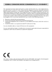
Read-Only Word Data: Function code [04H]
Relative
Register
address number (H)
Data
type
Oxygen concentration (%) after moving
avarage {Upper}
DWORD
Oxygen concentration (%) after moving
avarage {Lower}
mV corresponding value of Oxygen
{Upper}
DWORD
mV corresponding value of Oxygen
{Lower}
0
30001
1
30002
2
30003
3
30004
4
30005
5
30006
6
30007
7
30008
8
30009
9
30010
10
30011
11
30012
12
30013
WORD
13
30014
WORD
14
15
16
17
30015
30016
30017
30018
Memory contents
WORD Heater temperature (°C)
Combustion efficiency display function
(%)
Maximum value of Oxygen concentration
{Upper}
DWORD
Maximum value of Oxygen concentration
{Lower}
Minimum value of Oxygen concentration
{Upper}
DWORD
Minimum value of Oxygen
concentration{Lower}
Second of corrent date {Upper}
WORD
Minute of corrent date {Lower}
Time of corrent date
{Upper}
WORD
Day of corrent date{Lower}
WORD
WORD
WORD
WORD
WORD
Date of corrent date{Upper}
Month of corrent date{Lower}
Year of corrent date{Upper}
Unused
Year of starting date for next time auto
calibration {Upper}
Month of starting date for next time auto
calibration {Lower}
Date of starting date for next time auto
calibration {Upper}
Time of starting date for next time auto
calibration {Lower}
Minute of starting date for next time auto
calibration {Upper}
Unused
Year of starting date for next time auto
blowdown {Upper}
Month of starting date for next time auto
blowdown{Lower}
26
Readout data
0 to 0xFFFFFFFF
(1 digit = 0.0001 vol%)
0 to 0xFFFFFFFF
(1digit = 0.001 mV)
0 to 0xFFFF
(1digit = 0.1 °C)
0 to 0xFFFF
(1digit = 0.1 %)
0 to 0xFFFFFFFF
(1digit = 0.0001 vol%)
0 to 0xFFFFFFFF
(1digit = 0.0001 vol%)
0 to 59
0 to 59
0 to 23
1:Sun, 2:Mon, 4:Tue, 8:Wed,
16:Thu, 32:Fri, 64:Sat
1 to 31
1 to 12
00 to 99
0
00 to 99
1 to 12
1 to 31
0 to 23
0 to 59
0
00 to 99
1 to 12
INZ-TN5A0506-E
Relative
Register
address number (H)
18
19
20
21
22
30019
30020
30021
30022
30023
Data
type
WORD
WORD
WORD
WORD
WORD
Memory contents
Day of starting date for next time auto
blowdown {Upper}
Time of starting date for next time auto
blowdown {Lower}
Minute of starting date for next time auto
blowdown {Upper}
Unused
Unused
Unused
Unused
Event parameter {Upper}
23
30024
WORD
Event parameter {Lower}
24
INZ-TN5A0506-E
30025
WORD Event parameter {Upper}
27
Readout data
1 to 31
0 to 23
0 to 59
0
0 bit: Zero input adjustment
1 bit: Span input adjustment
2 bits: input adjustment of
zero temperature
3 bits: input adjustment of
temperature span
4 bits: input adjustment
auxiliary zero
5 bits: input adjustment of
auxiliary span
6 bits: 4 mA adjustment flag
7 bits: 20 mA adjustment
flag
(0: None, 1: Active)
0 bit: Manual span
calibration
1 bit: Auto span calibration
2 bits: Auto zero calibration
3 bits: Auto zero calibration
4 bits: Manual batch
calibration
5 bits: Auto calibration start
6 bits: Auto blowdown
7 bits: Manual blowdown
(0: None, 1: Active)
0 bit: Manual sensor
diagnosis
1 bit: Sensor diagnosis
(during calibration)
3 bits: Manual reactivated
sensor
4 bits: Activated sensor
(during calibration)
6 bits: Applied AC
7 bits: High-temperature
sensor
(0: None, 1: Active)
Relative
Register
address number (H)
24
30025
Data
type
Memory contents
WORD Event parameter {Lower}
Event parameter {Upper}
25
30026
WORD
Event parameter {Lower}
28
Readout data
0 bit :Write calibration factor
to EEPROM
1 bit :Span valve switching
(1: Open, 0: Close)
2 bits:Zero valve switching
(1: Open, 0: Close)
4 bits:Calculation reset
5 bits:Monitoring flag for
backlight off time
6 bits:Keylock status
7 bits:Inhibitation of
calibration status
(0: None 1: Active)
0 bit:Heater control
1 bit:Hold signal
2 bits:Warm up operation
HOLD
4 bits:Key input for
backlight off
5 bits:Restored sonsor to
wait high-temperature
6 bits:Auto blow start
7 bits:Manual batch
calibration
(0: None 1: Active)
0 bit: During remote heater
OFF
1 bit: Holding remote analog
output
2 bits: Excute sensor
dignausis during manual
ZERO calibration
3 bits: Excute sensor
dignausis during auto
calibration
4 bits: Number of execution
of restored sensor during
auto calibration
5 bits: Low temperature
warm-up opereation
6 bits: Remote calibration
7 bits: Remote blow
(0: None, 1: Active)
INZ-TN5A0506-E
Relative
Register
address number (H)
26
30027
27
30028
28
30029
INZ-TN5A0506-E
Data
type
Memory contents
Readout data
0 bit: Disconnection of
sensor
1 bit: Disconnection of
thermocouple line for
temperature control
2 bits: Disconnection of
thermocouple for
Parameter for alarm control{Upper}
combustion management
3 bits: Impedance setting
error
4 bits: Sensor abnormal
5 bits: O2 scale over
WORD
(0:Normal, 1: Abnormal)
0 bit: Secured error of span
gas calibration
1 bit: Span calibration error
2 bits: Secured error of zero
gas calibration
3 bits: Zero calibration error
Parameter for alarm control{Lower}
4 bits: Calibration error
6 bits: Timeout of hightemperature setting of
heater
(0: Normal, 1: Abnormal)
0 bit: Warm-up operation
error
1 bit: Heater temperature
Parameter for alarm control {Upper}
error
2 bits: A/D saturated error
5 bits: O2 error
(0: Normal 1:Abnormal)
0 bit: O2 upper2 limit value
alarm
WORD
1 bit: O2 upper limit value
alarm
2 bits: O2 lower limit value
alarm
Parameter for alarm control {Lower}
3 bits: O2 lower2 limit value
alarm
4 bits: Alarm information
5 bits: Fault imformation
7 bits: Rich mode
(0: Normal, 1: Abnormal)
0: Unexecute remote
Digital contact input Remote calibration
calibration
start {Upper}
1: Execute remote calibration
WORD
Digital contact input Inhabitation of
0: Calivration valid
calibration {Lower}
1: Inhibitation of calibration
29
Relative
Register
address number (H)
Data
type
Memory contents
0: Unexecute remote
blowdown
1: Execute remote blow
down
0: Unexecute calculation
Digital contact input Calculation reset
reset
{Lower}
1: Execute calcuration reset
0: Digital input 1 is ON
Digital contact input (1) Status {Upper}
1: Digital input 1 is OFF
0: Digital input 2 is ON
Digital contact input (2) Status {Lower}
1: Digital input 2 is OFF
0: Digital input 3 is ON
Digital contact input (3) Status {Upper}
1: Digital input 3 is OFF
Spare
110% of Input value of AO {Upper}
0 to 0xFFFFFFFF
110% of Input value of AO {Lower}
AD1 (O2 concentration) {Upper}
0 to 0xFFFFFFFF
AD1 (O2 concentration) {Lower}
AD2 (Heater temperature control)
{Upper}
0 to 0xFFFFFFFF
AD2 (Heater temperature control)
{Lower}
AD3 (combustion control) {Upper}
0 to 0xFFFFFFFF
AD3 (combustion control) {Lower}
AD4 (Thermocouple ambient
temperature) {Upper}
0 to 0xFFFFFFFF
AD4 (Thermocouple ambient
temperature) {Lower}
Oxygen concentration (%)mv −> % after
conversion {Upper}
0 to 0xFFFFFFFF
Oxygen concentration (%)mv −> % after (1 digit = 0.0001 vol%)
conversion{Lower}
Oxygen concentration (%) for analog out 0 to 0xFFFF
Sensor temperature (counter value)
{Upper}
0 to 0xFFFFFFFF
Sensor temperature (counter value)
{Lower}
mV conversion value of heater
temperature {Upper}
0 to 0xFFFFFFFF
(1 digit = 0.001 mv)
mV conversion value of heater
temperature {Lower}
mV conversion value of heater
0 to 0xFFFFFFFF
temperature {Upper}
(1 digit = 0.001 mv)
Average heater temperature mV {Lower}
Heater temperature (°C) (After
0 to 0xFFFF
temperature compensation, after
(1 digit = 1 °C)
Linearization)
Digital contact input
{Upper}
29
30030
WORD
30
30031
WORD
31
30032
WORD
32
33
34
35
30033
30034
30035
30036
36
30037
DWORD
DWORD
DWORD
37
30038
38
39
30039
30040
40
30041
41
30042
42
30043
DWORD
DWORD
DWORD
43
30044
44
30045
45
30046
WORD
DWORD
46
30047
47
30048
48
30049
49
30050
50
30051
51
30052
DWORD
DWORD
WORD
Readout data
30
Blow down
INZ-TN5A0506-E
Relative
Register
address number (H)
52
30053
53
30054
54
30055
55
30056
56
30057
57
30058
58
30059
59
30060
60
30061
61
62
63
64
65
66
67
30062
30063
30064
30065
30066
30067
30068
68
30069
69
30070
70
30071
71
30072
72
73
30073
30074
74
30075
75
30076
76
77
78
30077
30078
30079
INZ-TN5A0506-E
Data
type
Memory contents
mV conversion value of auxiliary input
temperature {Upper}
DWORD
mV conversion value of auxiliary input
temperature {Lower}
Average of mV combustion control
{Upper}
DWORD
Average of mV combustion control
{Lower}
WORD Combustion efficiency temperature
Thermocouple (RCJ) (AD value) {Upper}
DWORD Thermocouple (RCJ) (AD value)
{Lower}
Average value of thermocouple (RCJ)
{Upper}
DWORD
Average value of thermocouple (RCJ)
{Lower}
Heater temperature input zero {Upper}
DWORD
Heater temperature input zero {Lower}
Heater temperature input span {Upper}
DWORD
Heater temperature input span {Lower}
WORD PWM oncounter
Deviation of heater temperature {Upper}
DWORD
Deviation of heater temperature {Lower}
Previous deviation of heater temperature
{Upper}
DWORD
Previous deviation of heater temperature
{Lower}
Last deviation but one of heater
temperature {Upper}
DWORD
Last deviation but one of heater
temperature {Lower}
Manipulating value (%) {Upper}
DWORD
Manipulating value (%) {Lower}
MAX MIN calculated time (countdown)
{Upper}
DWORD
MAX MIN calculated time (countdown)
{Lower}
WORD Impedance EO
WORD Impedance EC
WORD Impedance Offset
31
Readout data
0 to 0xFFFFFFFF
(1 digit = 0.001 mv)
0 to 0xFFFFFFFF
(1 digit = 0.001 mv)
0 to 0xFFFF
(1 digit = 0.1 °C)
0 to 0xFFFFFFFF
0 to 0xFFFFFFFF
0 to 0xFFFFFFFF
0 to 0xFFFFFFFF
0 to 50
0 to 0xFFFFFFFF
(1 digit = 0.0001 °C)
0 to 0xFFFFFFFF
(1 digit = 0.0001 °C)
0 to 0xFFFFFFFF
(1 digit = 0.0001 °C)
0 to 10000
0 to 0xFFFFFFFF
0 to 0xFFFF
0 to 0xFFFF
0 to 0xFFFF
Read-Only Word Data (Function Code: 04H)
Information of error history
Relative
Register
address number (H)
Data
type
1000
31001
WORD
1001
31002
WORD
1002
31003
WORD
~
~
~
1007
31008
WORD
1008
1009
1010
~
1041
1042
1043
31009
31010
31011
~
31042
31043
31044
WORD
WORD
WORD
~
WORD
WORD
WORD
Memory contents
Stored number of error history {Upper}
Next storage pointer {Lower}
Data storaged of head pointer (Latest) {Upper}
Data storaged of end pointer (Oldest) {Lower}
Error code of data strorage position 0 {Upper}
Error code of data strorage position 1 {Lower}
~
Error code of data strorage position 10 {Upper}
Error code of data strorage position 11 {Lower}
Year of data storage position 0 at error generation
date {Upper}
Month of data storage position 0 at error
generation date {Lower}
Day of data storage position 0 at error generation
date {Upper}
Time of data storage position 0 at error generation
date {Lower}
Minute of data storage position 0 at error
generation date {Upper}
Second of data storage position 0 at error
generation date {Lower}
~
Year of data storage position 11 at error
generation date {Upper}
Month of data storage position 11 at error
generation date {Lower}
Day of data storage position 11 at error
generation date {Upper}
Year of data storage position 11 at error
generation date {Lower}
Minute of data storage position 11 at error
generation date {Upper}
Second of data storage position 11 at error
generation date {Lower}
32
Readout
data
0 to 12
0 to 11
0 to 11
0 to 11
0 to 255
0 to 255
~
0 to 255
0 to 255
Default
value
0
0
0
0
0
0
~
0
0
00 to 99
0
1 to 12
1
1 to 31
1
0 to 23
0
0 to 59
0
0 to 99
0
~
~
00 to 99
0
1 to 12
1
1 to 31
1
0 to 23
0
0 to 59
0
0 to 99
0
INZ-TN5A0506-E
Read-Only Word Data (Function Code: 04H)
Information of alarm history
Relative
Register
address number (H)
Data
type
2000
32001
WORD
2001
32002
WORD
2002
32003
WORD
~
~
~
2007
32008
WORD
2008
2009
2010
~
2041
2042
2043
INZ-TN5A0506-E
32009
32010
32011
~
32042
32043
32044
WORD
WORD
WORD
~
WORD
WORD
WORD
Memory contents
Stored number of alarm history {Upper}
Next storage pointer{Lower}
Data storaged of end pointer (Latest) {Upper}
Data storaged of head pointer (Oldest) {Lower}
Error code of data storage position 0 {Upper}
Error code of data storage position 1 {Lower}
~
Error code of data storage position 10 {Upper}
Error code of data storage position 11 {Lower}
Year of data storage position 0 at alarm
generation date {Upper}
Month of data storage position 0 at alarm
generation date {Lower}
Dayof data storage position 0 at alarm generation
date {Upper}
Time of data storage position 0 at alarm
generation date {Lower}
Minute of data storage position 0 at alarm
generation date {Upper}
Second of data storage position 0 at alarm
generation date {Lower}
~
Year of data storage position 11 at alarm
generation date{Upper}
Month of data storage position 11 at alarm
generation date {Lower}
Day of data storage position 11 at alarm
generation date {Upper}
Time of data storage position 11 at alarm
generation date {Lower}
Minute of data storage position 11 at alarm
generation date {Upper}
Second of data storage position 11 at alarm
generation date {Lower}
33
Readout
data
0 to 12
0 to 11
0 to 11
0 to 11
0 to 255
0 to 255
~
0 to 255
0 to 255
Default
value
0
0
0
0
0
0
~
0
0
00 to 99
0
1 to 12
1
1 to 31
1
0 to 23
0
0 to 59
0
0 to 99
0
~
~
00 to 99
0
1 to 12
1
1 to 31
1
0 to 23
0
0 to 59
0
0 to 99
0
Read-Only Word Data (Function Code: 04H)
Information of operation history
Relative
Register
address number (H)
Data
type
3000
33001
WORD
3001
33002
WORD
3002
33003
WORD
~
~
~
3007
33008
WORD
3008
33009
WORD
3009
3010
33010
33011
WORD
WORD
~
~
~
3041
33042
WORD
3042
3043
33043
33044
WORD
WORD
Memory contents
Stored number of operation history {Upper}
Next storage pointer {Lower}
Data storaged head pointer (Latest) {Upper}
Data storaged end pointer (Oldest) {Lower}
Error code of data storage position 0 {Upper}
Error code of data storage position 1 {Lower}
~
Error code of data storage position 10 {Upper}
Error code of data storage position 11 {Lower}
Year of data storage position 0 at operation
generation date {Upper}
Month of data storage position 0 at operation
generation date {Lower}
Day of data storage position 0 at operation
generation date {Upper}
Time of data storage position 0 at operation
generation date {Upper}
Minute of data storage position 0 at operation
generation date {Upper}
Second of data storage position 0 at operation
generation date {Lower}
~
Year of data storage position 11 at operation
generation date {Upper}
Month of data storage position 11 at operation
generation date {Lower}
Day of data storage position 11 at operation
generation date {Upper}
Time of data storage position 11 at operation
generation date {Lower}
Minute of data storage position 11 at operation
generation date {Upper}
Second of data storage position 11 at operation
generation date {Lower}
34
Readout
data
0 to 12
0 to 11
0 to 11
0 to 11
0 to 255
0 to 255
~
0 to 255
0 to 255
Default
value
0
0
0
0
0
0
~
0
0
00 to 99
0
1 to 12
1
1 to 31
1
0 to 23
0
0 to 59
0
0 to 99
0
~
~
00 to 99
0
1 to 12
1
1 to 31
1
0 to 23
0
0 to 59
0
0 to 99
0
INZ-TN5A0506-E