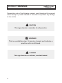
1
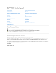
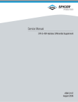
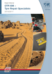
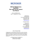
Operator's Handbook Publication No: 2012 Revised June 2000 Sabre - 2012 - 06/00 FOREWORD The purpose of this handbook is to provide drivers with information to help them to operate their vehicles safely and efficiently. Care and attention given at the right time will ensure efficient and satisfactory performance. Periodic attention is necessary, and should help to avoid breakdowns. Never run the vehicle in a doubtful condition always report back to the garage for inspection and attention. Dennis reserve the right to change the procedures, materials, specification, dimensions or design of the vehicle shown, described or referred to herein at any time and without prior notice in accordance with the Company's policy of constant product improvement. It is recommended that this handbook is kept with the vehicle. This handbook is based on the chassis and original equipment fitted at the factory. You should therefore bear in mind that the bodybuilder may have made changes to the vehicle. For this reason, you may find illustrations and / or certain parts of the text in this handbook which do not correspond exactly to the particular situation on your own vehicle. In all communications quote the relevant V.I.N., WPO and engine number. This will ensure prompt attention. DENNIS FIRE Dennis Way Guildford Surrey GU1 1AF England Telephone: Fax: + 44 (0)1483 571271 + 44 (0)1483 301697 3 CONTENTS Page 4 Foreword . . . . . . . . . . . . . . . . . . . . . . . . . . . . . . . 3 Contents . . . . . . . . . . . . . . . . . . . . . . . . . . . . . . . . 4-5 Product Warning Signs . . . . . . . . . . . . . . . . . . . . . 6 General Description . . . . . . . . . . . . . . . . . . . . . . . 7 Vehicle Identification . . . . . . . . . . . . . . . . . . . . . . . 8 Vehicle Identification Sheet . . . . . . . . . . . . . . . . . . 9 Warning Light Panel . . . . . . . . . . . . . . . . . . . . . . . 10 - 17 Instruments . . . . . . . . . . . . . . . . . . . . . . . . . . . . . . 18 - 19 Switches and Controls . . . . . . . . . . . . . . . . . . . . . 20 - 35 Starting and Driving . . . . . . . . . . . . . . . . . . . . . . . . 36 - 42 A.B.S./A.S.R . . . . . . . . . . . . . . . . . . . . . . . . . . . . . 43 - 44 Power Take Off . . . . . . . . . . . . . . . . . . . . . . . . . . . 45 - 48 Cab Tilt Procedure . . . . . . . . . . . . . . . . . . . . . . . . 49 - 52 Towing . . . . . . . . . . . . . . . . . . . . . . . . . . . . . . . . . 53 Service Points Diagram . . . . . . . . . . . . . . . . . . . . . 54 Daily Maintenance Checks . . . . . . . . . . . . . . . . . . 54 - 55 Weekly Maintenance Checks . . . . . . . . . . . . . . . . 56 Lubricants and Fluids . . . . . . . . . . . . . . . . . . . . . . 57 Supplementary Coolant Additive . . . . . . . . . . . . . . 58 Fuses . . . . . . . . . . . . . . . . . . . . . . . . . . . . . . . . . . 59 Tyre Pressures . . . . . . . . . . . . . . . . . . . . . . . . . . . 60 Wheels and Tyres . . . . . . . . . . . . . . . . . . . . . . . . . 60 - 61 Jacking Points . . . . . . . . . . . . . . . . . . . . . . . . . . . . 62 Front Seats Adjustment . . . . . . . . . . . . . . . . . . . . . 63 Safety Belt Anchorages . . . . . . . . . . . . . . . . . . . . . 64 Electric Windows . . . . . . . . . . . . . . . . . . . . . . . . . 65 Cab Interior Lights . . . . . . . . . . . . . . . . . . . . . . . . . 66 CONTENTS Page Optional Fittings Air Conditioning . . . . . . . . . . . . . . . . . . . . . . . . . . 67 Flashing Headlamps . . . . . . . . . . . . . . . . . . . . . . . 67 Central Locking . . . . . . . . . . . . . . . . . . . . . . . . . . . 67 Auto Chassis Lubrication . . . . . . . . . . . . . . . . . . . . 68 Circuit Breakers . . . . . . . . . . . . . . . . . . . . . . . . . . 69 CRT Exhaust . . . . . . . . . . . . . . . . . . . . . . . . . . . . 70 Digital Clock . . . . . . . . . . . . . . . . . . . . . . . . . . . . . 70 Ferry Lift . . . . . . . . . . . . . . . . . . . . . . . . . . . . . . . . 71 Polycarbonate Coated Side Glass . . . . . . . . . . . . . 72 Powermite Alternator . . . . . . . . . . . . . . . . . . . . . . . 72 - 73 Retarder . . . . . . . . . . . . . . . . . . . . . . . . . . . . . . . . 74 Safety Wheel Nuts . . . . . . . . . . . . . . . . . . . . . . . . 75 Towing and Recovery . . . . . . . . . . . . . . . . . . . . . . 76 - 77 Water Heater . . . . . . . . . . . . . . . . . . . . . . . . . . . . 77 5 PRODUCT WARNINGS Please take note of the following symbols, used throughout this manual which identify any health hazards or instructions to prevent any damage to the vehicle. m CAUTION This sign denotes a reminder of safe practice. H WARNING This is a prohibition sign. It denotes a hazard and indicates a practice not to be followed. m DANGER This sign denotes an extreme, constant hazard. 6 GENERAL DESCRIPTION Vehicles covered in this publication are:- Sabre & Sabre HD, fitted with Standard, ML 200, XL or Single cab. The Dennis Sabre is a fire appliance chassis, manufactured to meet the exact requirements of Fire Brigades. It is powered by a 6 cylinder turbo charged, after cooled diesel engine, driving a single reduction hypoid rear axle through a five speed automatic gearbox. The air braking system is charged by a compressor supplying air reservoirs through a dryer. The front brakes are air actuated Reaction Beam Caliper Disc Brakes and the rear brakes are air actuated Fixed Cam Sliding Shoe Brakes. There is also an antilock braking system with optional traction control. Front suspension is multi-leaf, semi-elliptical spring with telescopic damper. Rear suspension is coil or air sprung located by taper leaf springs and also features telescopic dampers. The 24 volt electrical system is charged by an engine driven alternator charging 2 batteries, and is wired negative earth. 7 VEHICLE IDENTIFICATION Vehicle details can be identified from the typical V.I.N. plate shown below. The V.I.N. plate is located in the driver's footwell. Please quote the V.I.N. number with any enquiries concerning the vehicle. DENNIS GUILDFORD, ENGLAND W.P.O. 44355 VEHICLE TYPE SABRE ENGINE TYPE CUMMINS C260 10 CAB TYPE FDHS01ARB A V.I.N. SFD122C12WGS41234 B 14500 Kg 13000 Kg C Kg Kg D 5500 Kg 5500 Kg E 9000 Kg 7500 Kg F Kg G Kg PLATED WEIGHTS DESIGN WEIGHTS Key to V.I.N. Plate SFD World Manufacturers Identity A Type Approval Number 1 Wheelbase B Vehicle Identification Number 1 Engine C Gross Weight 2 Transmission D Train Weight C P.T.O. Type / Ratio E Axle 1 Weight 1 Axle Type / Ratio F Axle 2 Weight 2 Series/mark G Axle 3 Weight W Build/Year G Build Plant S Model 4 Cab 1234 8 Serial Number VEHICLE IDENTIFICATION SHEET CHASSIS V.I.N. No . . . . . . . . . . . . . . . . . . . . . . . . . . . . . . . . . . . . . . . . . . . . . . Model . . . . . . . . . . . . . . . . . . . . . . . . . . . . . . . . . . . . . . . . . . . . . . . . Registration No . . . . . . . . . . . . . . . . . . . . . . . . . . . . . . . . . . . . . . . . . Date into service . . . . . . . . . . . . . . . . . . . . . . . . . . . . . . . . . . . . . . . . Engine Type . . . . . . . . . . . . . . . . . . . . . . . . . . . . . . . . . . . . . . . . . . . . Engine Number . . . . . . . . . . . . . . . . . . . . . . . . . . . . . . . . . . . . . . . . . Gearbox Type . . . . . . . . . . . . . . . . . . . . . . . . . . . . . . . . . . . . . . . . . . Gearbox Number . . . . . . . . . . . . . . . . . . . . . . . . . . . . . . . . . . . . . . . . Wheel Tyre Size . . . . . . . . . . . . . . . . . . . . . . . . . . . . . . . . . . . . . . . . . BODYWORK Bodybuilder . . . . . . . . . . . . . . . . . . . . . . . . . . . . . . . . . . . . . . . . . . . . Body Type . . . . . . . . . . . . . . . . . . . . . . . . . . . . . . . . . . . . . . . . . . . . . Body Number . . . . . . . . . . . . . . . . . . . . . . . . . . . . . . . . . . . . . . . . . . . OPERATOR Company . . . . . . . . . . . . . . . . . . . . . . . . . . . . . . . . . . . . . . . . . . . . . . Address . . . . . . . . . . . . . . . . . . . . . . . . . . . . . . . . . . . . . . . . . . . . . . . Telephone Number . . . . . . . . . . . . . . . . . . . . . . . . . . . . . . . . . . . . . . . Fax Number . . . . . . . . . . . . . . . . . . . . . . . . . . . . . . . . . . . . . . . . . . . . Out of Hours Telephone Number . . . . . . . . . . . . . . . . . . . . . . . . . . . . 9 WARNING LIGHT PANEL 10 WARNING LIGHT PANEL The following section lists some of the warning light options that are available. However each vehicle will carry only the requirements that were specified. Therefore the warning lights should be carefully studied during vehicle familiarisation. 1. Mast in Operation (Option) 2. Mains On (Option) 3. Battery on Charge (Option) 4. Fuel Heater (Option) 5. P.T.O. Engaged 6. Spare Warning Light No. 5 P.T.O. engaged is the only dedicated warning light. The other five positions are optional, you should therefore bear in mind that the body builder may have made changes to the vehicle. 11 WARNING LIGHT PANEL 12 WARNING LIGHT PANEL 7. Direction Indicator (left turn) Flashes in synchronisation with the left hand indicator lights. 8. High Beam Warning Light Comes on when headlights are on main beam. 9. Front Fog Light Indicator Comes on when front fog lights are on. 10. Rear Fog Light Indicator Comes on when rear fog lights are on. 11. Retarder Indicator Light Flashes when retarder is in operation. 12. Traction Control Indicator Light Flashes when traction control is in operation. 13. Oil Temperature (Automatic Gearbox) Comes on when the automatic gearbox temperature is too high. 14. Park Brake Warning Light Flashes when parking brake is applied. 15. Cab Lock Warning Light Illuminates when cab is in the unlocked condition. H WARNING Do not attempt to move the vehicle until the warning light (15) is out. 16. Master Warning Light Flashes when lights 20, 21, 22 & 27 are on. 13 WARNING LIGHT PANEL 14 WARNING LIGHT PANEL 17. Master Warning Light Flashes when indicator lights 20, 21, 22 & 27 are on. 18. Locker Door Open Warning Light Illuminates when a locker door is not correctly closed. 19. A.B.S. Warning Light Illuminates if a fault with the anti lock braking system. 20. Low Air Pressure Warning Light Comes on and a warning buzzer sounds when the air pressure in any system is below 78 psi (5.3 bar). 21. Oil Pressure Warning Light Illuminates if the engine oil pressure is too low. The fault must be found and rectified. 22. High Coolant Temperature Warning Light Comes on when engine coolant temperature rises above 102°C. 23. Transmission Check Light Illumination of this light indicates that a problem has been detected and shifts may be restricted. Operation may continue in order to reach service assistance. 24. Low Fuel Warning Light Comes on when the fuel level is low. 25. No Charge Warning Light Comes on when the alternator is not charging the battery. 26. Direction Indicator (right turn) Flashes in synchronisation with the right hand indicators. 15 WARNING LIGHT PANEL 16 WARNING LIGHT PANEL 27. Low Coolant Level Warning Light Light flashes and a buzzer sounds when the coolant level is low. 28. Power Steering Fluid level Comes on when power steering fluid level is low. 29. Brake Wear Indicator (front) Illuminates to indicate brake pads need renewing. 30. Spare 31. Spare 32. Spare 17 INSTRUMENTS 18 INSTRUMENTS 1. P.T.O. Hourmeter (Option) Records the number of hours that the P.T.O. has been operating. 2. Engine Hourmeter Records the number of hours that the engine has been operating. 3. Ammeter Indicates the charge/discharge rate. 4. Gearbox Oil Temperature Indicates the temperature of the gearbox oil. 5. Coolant Temperature Gauge Indicates the temperature of the engine coolant. 6. Oil Pressure Indicates engine oil pressure. 7. Voltmeter Indicates the voltage condition of the battery. 8. Speedometer Indicates the road speed and also the distance travelled. 9. Tachometer Indicates the speed RPM of the engine. 10. Air Pressure Gauge (Service 1) Indicates the air pressure in the front brake reservoir. 11. Air Pressure Gauge (Service 2) Indicates the air pressure in the rear brake reservoir. Should failure occur in either one of the two brake systems the remaining system will provide secondary braking. 12. Fuel Gauge Indicates the contents of the fuel tank. 19 SWITCHES AND CONTROLS 20 SWITCHES AND CONTROLS The following section lists all of the switch options that are available. However each vehicle will carry only the requirements that were specified. Therefore the switches should be carefully studied during vehicle familiarisation. 1. Hand Throttle Switch When on and locked allows engine speed to be controlled by hand throttle when items such as auxiliary generator are in use. 2. Option For Option SwItches See Page 34 3. OptIon For Option SwItches See Page 34 4. Option For Option SwItches See Page 34 5. Interior Light Switch 6. Locker Light Switch 7. Option 8. Heated Mirror Switch 9. Radio Switch Energises the voltage converter for the radio. 10. Rear Blue Flasher Switch Position 1 - off Position 2 - Rear blue flashers on Position 3 - Rear plus other function 11. Flashing Beacon Switch Position 1 - off Position 2 - Beacons on Position 3 - Beacons and front blue lights on 12. Two Tone Horn Switch 13. Two Tone Changeover 21 SWITCHES AND CONTROLS 0 1 2 22 SWITCHES AND CONTROLS 14. Master Switch 15. Hazard Warning Switch 16. Fog Lights Switch 17. Rear Fog Lights Switch 18. Bulb Test Switch Tests all the dashboard warning lights, and the warning buzzers. 19. Option For Option Switches See Page 34 20. Option For Option Switches See Page 34 21. Headlamp Adjuster Switch For electrically adjustable headlamps (if fitted) 23 SWITCHES AND CONTROLS 24 SWITCHES AND CONTROLS 22. Multi Function Switch Headlights Dipped beam / main beam / headlight flash: A Headlight dip beam B Headlight main beam C Headlight main beam flash Direction Indicators To operate the lane-change mode of the direction indicators, move the switch lightly against spring pressure and hold it in this position. The indicator switch should not be held against the action of the self cancelling mechanism. The direction indicators only work with the ignition switch at Run. D E F G Direction indicator right Direction indicator left Horn Windscreen wash Horn The horn is operated by moving the knob (F) inwards against spring pressure. Windscreen Wipers Position Position Position Position 0 I II J Wipers switched off Low speed High speed Intermittent wipe - in this position the wipers make a single sweep across the windscreen every eight seconds (if fitted). Windscreen Washers Pushing in the ring (G) actuates the screenwash jets pressure. 25 SWITCHES AND CONTROLS 26 SWITCHES AND CONTROLS 23. Parking Brake (handbrake) The parking brake is applied by pulling the lever down until it locks in position. To release the parking brake, the sleeve on the lever must first be pulled, then push the lever fully upwards. In the event that there is not enough air in the service brakes, the parking brake can be used as an emergency brake. H WARNING It is essential to apply the parking brake when leaving the vehicle. 24. Emergency Stop Control This stop control is only for use if failure of main switching device occurs. Under normal operating conditions the engine should be switched off by moving the engine start switch to the off position. 27 SWITCHES AND CONTROLS 28 SWITCHES AND CONTROLS 25. Steering Column Adjustment To release clamp: 1. Pull lever out and allow to engage on splines 2. Turn anti-clockwise to release clamp Repeat operations 1 - 2 until clamp is released sufficiently to move steering column. Column is adjustable for both rake and height. To tighten clamp: 3. Pull lever out and allow to engage on splines 4. Turn clockwise to tighten clamp Repeat operation 3 - 4 until clamp is tight. Ensure steering column is secure before driving vehicle. Under no circumstances should an attempt be made to adjust the steering column whilst the vehicle is in motion. 26. Engine Start Switch (key operated) 0 - Off I - Run II - Ill - Start Rocker Switch Stop Start Control on dashboard (Option) 27. Light Switch Off Sidelights Headlights 29 SWITCHES AND CONTROLS Push button selector 30 Lever selector SWITCHES AND CONTROLS 28. Transmission Shift Selector The fitted transmission shift selector may be of either the push button or lever type. Push Button Selector The function of each position of the keypad pushbutton shifter is as follows: Select Reverse gear by pressing R. Select Neutral by pressing N. The area around the N button is a raised ridge so the driver can orient his hand to the push buttons by touch, without looking at the display. It is not necessary to press this button prior to starting the vehicle. Select Drive range by pressing D. The highest forward gear will appear on the Select display and the transmission will shift to the starting gear. The Upshift and Downshift arrow buttons are used to select a higher (if not in D) or lower (if not in 1) forward range. These buttons are not functional in Neutral or Reverse. One press changes the range selected by one range. If the button is held continuously, the selected range will continue to change up or down until the button is released or until the highest or lowest possible range of gears is selected. Lever Selector (Option) The shift selector is used by the operator to select Neutral (N), Reverse gear (R), or a range of forward gears. When a forward gear range has been selected, the transmission starts in the lowest gear of the range and, as conditions permit, automatically upshifts until the highest gear in the selected range is in use. It is not necessary to select the right moment to upshift or downshift during changing road and traffic conditions. The transmission does it for you. However, knowledge of the gear ranges and when to select them will make vehicle control even easier. Mode Button The lever and keypad push button shift selectors feature a Mode button on the face of the shifter bezel. This button is used to engage the P.T.O. The red LED is illuminated when the function is activated. 31 SWITCHES AND CONTROLS 32 SWITCHES AND CONTROLS 29. Heating and Ventilation Upper Lever - Direction Control Left position - Floor Right position - Windscreen Lower Lever - Heat Control Left position (Blue) - Cold Right position (Red) - Hot Rotary Fan Switch 0 - Fan switched off 123 - Three fan speeds For optimum comfort the fan should be switched onto low speed when driving. m CAUTION To avoid drawing in dangerous fumes while stationary in traffic, it is advisable to switch the fan off and open door windows slightly for ventilation. Air Vents Air can be directed into the cab via vents on the dashboard. The air temperature and flow is controlled by the heater controls. The vents are opened by pushing against the flap, and the direction of flow is controlled by turning the outer bezel of the vent. Summer Ventilation: Open air vents. Slide direction control to midway position. Slide heat control fully to left - cold. Switch on fan. Windshield Demisting and Defrosting: Slide direction control fully to right. Slide heat control fully to right - hot. Close cold air vents. Select fastest speed on rotary fan switch. 33 SWITCHES AND CONTROLS Switch Options The switch lenses bearing the following symbols or words are for optional fittings. They are located on the switch panels. Symbol/Words Colour Option YELLOW Ferry lift- raise GREEN Ferry lift - lower GREEN Flashing headlamps ORANGE Electric cab tilt GREEN Audible reverse MAINS RED Auto electrics off Battery charger warning FUEL FILTER RED Water trap warning REVERSE HORN 34 SWITCHES AND CONTROLS Symbol/Words START HAND THROTTLE Colour Option RED Stop start via switch GREEN Winch GREEN Hand throttle GREEN Marker lights RED Aux. Alternator 35 STARTING AND DRIVING ENGINE Normal Starting Procedure Ensure master switch is on. Put transmission into neutral. If the engine is cold, fully depress the throttle AFTER engaging the starter. The inline pump requires open throttle to position and hold the rack in the maximum fuel position. Turn the ignition switch to start. Release the switch to run. Release accelerator to idle. If the engine is warm, the inline pump delivers sufficient fuel to start the engine with throttle at idle. m CAUTION To prevent damage to the starter, do not operate the starter motor for more than 30 seconds. Wait 2 minutes between each attempt to start. Check that oil pressure is indicating on the gauge within 15 seconds of starting. Check that the battery charge warning light goes out. If the engine is cold, increase the engine speed slowly to ensure adequate lubrication is fed to the bearings and to allow the oil pressure to stabilise. Engine Operation Monitor the oil pressure and coolant temperature gauges frequently. Shut the engine off if the oil pressure light comes on or if the coolant temperature gauge reads below 60°C or above 100°C. Stopping The Engine Allow the engine to idle for 3-5 minutes before shutting it off after a full load operation. 36 Turn engine off. STARTING AND DRIVING Check List Before Moving Off Check that the air pressure gauges are showing the correct operating pressures and low air pressure buzzers are extinguished. Check that no warning lights are on except for the handbrake and the A.B.S. indicator. m CAUTION Continuous operation with low coolant temperature below 60°C or high coolant temperature above 100°C can damage the engine. If an overheating condition starts to occur, reduce engine speed or shift to a lower gear, or both, until the temperature returns to normal operating range. If engine temperature does not return to normal report condition to service department. Most failures give an early warning. Look and listen for changes in performance, sound, or engine appearance that may indicate service or engine repair is needed. Some changes to look for are: Engine misfires Excessive smoke Vibration Loss of power An increase in oil consumption Fuel, oil or coolant leaks An increase in fuel consumption Unusual engine noises Sudden changes in engine operating temperature or pressure m CAUTION Engine overspeed (engine speed exceeds high idle with no load) can damage the engine. 37 STARTING AND DRIVING GEAR SELECTION The vehicle must be completely stopped before shifting from Forward to Reverse or from Reverse to Forward. The Select indicator will display R and the Monitor will display R when Reverse is attained. Use Neutral to start the engine, checking vehicle accessories, or for extended periods of engine idle operation. If the engine starts in any other selected gear, the start circuit should be serviced immediately. Neutral is also used during stationary operation of the power take off. The Select indicator will display Neutral and the Monitor will display Neutral. H WARNING Do not allow your vehicle to coast in Neutral. This can result in transmission damage. Also, no engine braking is available in Neutral. The vehicle will attain first gear when D is selected, and as the speed increases, the transmission will automatically upshift through each gear. As the vehicle slows down, the transmission will automatically down shift. The Monitor will display the current operating gear. 38 4 3 2 Occasionally, the road conditions, load, or traffic conditions will make it desirable to restrict the automatic shifting to a lower gear. These positions also provide progressively greater engine braking for going down grades (the lower the gear, the greater the braking effect). 1 Use this gear when pulling through mud and deep snow, when manoeuvring in tight spaces, or while driving up or down grades. Low gear provides the vehicle with its maximum driving power and maximum engine braking power. STARTING AND DRIVING Push Button Selector The push button selector utilises Arrow Buttons. Push the Up or Down arrow to the desired gear. The Monitor will display the selected gear when it is attained. The transmission incorporates a hold feature to prohibit upshifting above the gear selected during normal driving. For downhill operation, however, the transmission may upshift above the highest selected gear when governed speed is exceeded and damaging the engine by overspeed is a possibility. H WARNING In the event of it becoming necessary to leave the vehicle, even momentarily, while the engine is running, be sure that the transmission is in neutral, parking brake is set and properly engaged. Unexpected and possibly sudden vehicle movement may occur if these precautions are not taken. TRANSMISSION Transmission Check Light The transmission Electronic Control Unit (E.C.U.) is programmed to inform you if operating parameters have been exceeded and automatically take action to protect the operator, vehicle, and transmission. To do this, the E.C.U. turns on the Transmission check light on the instrument panel. A diagnostic code will be registered when the light is active. Illumination of this light will notify the operator that the transmission is not performing as designed. Although the transmission can continue to operate, service advice should be sought promptly. The vehicle may continue to be driven to complete the desired mission if conditions can be negotiated safely. However, in some cases the E.C.U. will take action, such as inhibiting upshifts. The readout digit on the shifter display may be blank. Direction change will not occur. 39 STARTING AND DRIVING TRANSMISSION Accelerator Control The position of the accelerator pedal influences the timing at which automatic shifting occurs. When the pedal is fully depressed, upshifts will occur automatically at high engine speeds. A partially depressed position of the pedal will cause the upshifts to occur at lower engine speeds. Downshift or Reverse Inhibitor Feature Although there is no speed limitation on upshifting, there is on downshifting and shifts to reverse. If a downshift is selected at too high a speed, the ECU will prevent the shift from occurring until a lower speed is reached. If idle speed is too high, shifts to range are inhibited. A continuous beep tone is emitted if reverse is selected during forward movement, or Neutral to a range gear is selected at too high an engine speed. Oil Level Sensor Readout When the oil level sensor is in operation, the transmission selector can be used to indicate oil level as follows: The engine must be at idle and in neutral The vehicle must be stationary and on a level surface The transmission oil must be within the normal operating temperature band (60°C - 104°C) When the above conditions are met a 2 minute waiting period should be allowed for oil to drainback. Using the Keypad Selector Simultaneously press the Upshift and Downshift arrows on the selector. The display will indicate the reading code the display will flash O-L-O-K, L-O-0-1" ,H-l-0-2, etc., where the suffix "0-1" or 0-2 indicate the volume of oil (in litres) low or high. Using the Lever Selector Press the diagnostic button (with the Allison Logo) the readout is as for keypad selector. 40 STARTING AND DRIVING TRANSMISSION Using the Engine to Slow the Vehicle or Equipment To use the engine as a braking force, select the next lower gear. If the vehicle is exceeding the maximum speed for this gear, use the service brakes to slow the vehicle. When a lower speed is reached, the E.C.U. will automatically downshift the transmission. Engine braking provides good speed control for going down hills. When the vehicle is heavily loaded, or the hill is steep, it may be desirable to preselect a lower gear prior to going downhill. Gear Preselection Gear preselection means selection of a lower gear to match driving conditions you encounter or expect to encounter. Learning to take advantage of preselect will give you better control on slick or icy roads and when going up or down hills. Downshifting to lower gears increases engine braking. Selecting a lower gear often prevents cycling between a gear and the next higher gear on a series of short up and down hills. Rocking Out If the vehicle is stuck in deep sand, snow or mud, it may be possible to rock it out. Select drive (D) and apply steady, light throttle (never full throttle). When the vehicle has rocked forward as far as it will go, apply and hold the vehicle service brakes. Allow the engine to return to idle; then select reverse. Release the brakes and apply a steady, light throttle and allow the vehicle to rock in reverse as far as it will go. Again, apply and hold the service brakes and allow the engine to return to idle. This procedure may be repeated in drive and reverse if each directional change continues to move the vehicle a greater distance. Never make neutral-to-drive or directional shift changes when the engine rpm is above idle. m CAUTION Do not make Neutral-to-Drive or directional shift changes when the engine rpm is above idle. If the wheels are stuck and not turning, do not apply full power for more than 30 seconds. 41 STARTING AND DRIVING TRANSMISSION High Oil Temperature If the transmission oil temperature reaches 121°C (250°F) the WARNING light will come on but the E.C.U. will not inhibit operation in higher gear. If the transmission overheats during normal operation, check the oil level in the transmission. If the WARNING light comes on and the engine temperature gauge indicates a high temperature, the transmission is probably overheated. Stop the vehicle and check the cooling system. If it appears to be functioning properly, run the engine at 1200-1500 rpm with the transmission in Neutral. This should reduce the transmission and engine temperatures to normal operating levels in two or three minutes. m CAUTION The engine should never be operated for more than 30 seconds at full throttle with the transmission in gear and the output stalled. Prolonged operation of this type will cause the transmission oil temperature to become excessively high and will result in severe overheat damage to the transmission. If the engine temperature gauge indicates a high temperature and the WARNING light is not on, an engine problem is indicated. If high temperature in either the engine or transmission persists, stop the engine and have the overheating condition investigated by maintenance personnel. If the vehicle continues to be operated with the transmission oil temperature warning light illuminated, retarder performance may be reduced and top gear performance inhibited. 42 A.B.S. / A.S.R. ANTI-LOCK BRAKING SYSTEM (A.B.S.) The anti-lock braking system works in conjunction with the vehicle's air braking system to prevent wheel lock and out of control skidding. During braking, electronic sensors on each wheel evaluate wheel speeds. Wheel performance is fed to a micropressor which senses when a wheel is about to lock. Brake pressure is then adjusted both to prevent the wheel from sliding and to maintain optimum braking. The system is sensed off all four wheels, and all are controlled individually. Once the ignition key is turned on, Amber A.B.S. warning lamp will illuminate. This is normal procedure. A sequence of clicks will also be heard, this is the pulse check initiated by the A.B.S. Electronic Control Unit. It checks that A.B.S. modulator valves are responding. Driving off in the vehicle, notice the A.B.S. warning lamp. It will extinguish once the speed of the vehicle has reached 4 mph (7 km/h). If it remains on, the ECU has detected a fault. The A.B.S. warning lamp will only illuminate in other circumstances if a fault has been detected. Normal braking is available when this occurs. Drive with care. The vehicle should be sent to a service agent at the first opportunity. The ABS system is designed to enable vehicle control to be maintained. Braking distances may increase when the ABS is cycling. TRAFFIC CALMING MEASURES When traffic calming measures (sleeping policemen) are encountered it is recommended that the maximum speed of the vehicle does not exceed 15 mph. 43 A.B.S. / A.S.R. ANTI-SLIP REGULATION A.S.R. (Optional fitment) The anti-slip regulation is an extension of the A.B.S. and prevents wheel spin or loss of traction when accelerating. A.S.R. is effective in slush, ice, snow or mud. The same A.B.S. wheel speed sensing device transmits a signal to the control unit. Control signals are then transmitted to brake control valves to regulate brake applications or to the engine fuel supply to reduce the power. If only one wheel is spinning the brake on that wheel will be applied to transfer drive energy through the differential to the wheel not spinning. If both wheels are spinning the Electronic Control Unit (E.C.U.) will signal a fuel control device to reduce engine power to match the friction available. 44 POWER TAKE OFF POWER TAKE OFF (PTO) To engage Ensure handbrake is applied and engine revs are at idle. Select Neutral. Press Mode on push button control. The display will indicate Mode On when activated. Red warning light will illuminate when PTO is engaged. If the engine is stopped with the PTO engaged the PTO disengages. To Disengage Return engine speed to idle. Press Mode button. Warning light will extinguish when PTO is disengaged. Hand throttle operation is independent of PTO switch on dash. Webster PTO 142% ratio If the above PTO is fitted, ensure that when pumping at Low Pressure the pump revs do not exceed 3150rpm; and when Combined Pumping (Low & High Pressure) the pump revs do not exceed 2750rpm. H WARNING Ensure hand throttle is closed before switching off engine. Power take off interlocks are fitted to prevent accidental engagement of PTO. If the handbrake is released with the PTO engaged a warning buzzer will sound. Do not work underneath the vehicle with the engine running. Do not attempt to work on the PTO with the engine running. 45 POWER TAKE OFF To increase engine speed independent of PTO engagement (for air tool or auxiliary alternator use etc), first ensure the vehicle is in neutral with the handbrake engaged, activate hand throttle switch on dash. m DANGER During extreme cold weather cold weather (32°F - 0°C and under) the PTO can momentarily transmit high torque which can cause output shaft rotation in the disengaged position. This is caused by the oil being extremely cold. Do not engage the PTO until the transmission is warmed up. AUXILIARY POWER TAKE OFF( PTO - if fitted) To Engage Ensure handbrake is applied and engine revs are at idle. Select Neutral (if driveline PTO is already selected, return engine revs to idle). Press Mode on gearchange control. Red warning light will illuminate when PTO is engaged. To Disengage Return engine speed to idle. Press Mode button. Warning light will extinguish when PTO is disengaged. DRIVELINE POWER TAKE OFF (PTO) To Engage Ensure handbrake is applied and engine revs are at idle. Select Neutral on gearchange control. Activate Driveline PTO button on dash. Pump Requested & Pump Engaged warning light will illuminate. Select Drive on gearchange control. Ready to Pump warning light will illuminate. 46 POWER TAKE OFF CHECK GEAR SELECTION IMMEDIATELY IF CONTINUOUS AUDIBLE WARNING SOUNDS. To Disengage Return engine speed to idle. Select Neutral on gearchange control. When N is displayed under Monitor heading, driveline PTO button can be deactivated. Warning lights will extinguish when PTO is disengaged. Warning lights will not extinguish for 4 seconds. PTO WITH LADDER. Engine with stop/start facility. To engage Ensure handbrake is applied and engine revs are at idle. Select Neutral. Press Mode on push button control. The display will indicate Mode On when activated. Red warning light will illuminate when PTO is engaged. If the engine is stopped with the PTO engaged the PTO disengages. To Disengage Return engine speed to idle. Press Mode button. Warning light will extinguish when PTO is disengaged. H WARNING Do not work underneath the vehicle with the engine running. Do not attempt to work on the PTO with the engine running. 47 POWER TAKE OFF PTO INTERLOCK SYSTEM 48 PTO operates from the mode button (Press for engage / Press for disengage). PTO will not engage Unless the transmission is in neutral When the engine revs are above 900 rpm When the handbrake is in the off position. PTO will not disengage When the engine revs are above 820 rpm. Drive cannot be selected When the vehicle is in PTO mode When the engine revs are above idle. Selecting PTO inhibits use of the accelerator pedal. Rear hand throttle cannot be used unless the handbrake is in the on position. The rear hand throttle cannot be operated independently of the PTO, unless the dash switch is activated (dash switch will only operate in neutral). Releasing the handbrake whilst rear hand throttle is activated will sound audible alarm. Electrical failure disengages the PTO. CAB TILT PROCEDURE m CAUTION When raising or lowering the cab it is important to follow the procedures listed to avoid accidents to personnel or damage to the vehicle. PROCEDURE BEFORE TILTING CAB Ensure the vehicle is on level ground before tilting cab. Engine must be off. Apply parking brake or chock the wheels. Fasten or remove all loose items in the cab. It may be necessary to remove the Breathing Apparatus (BA) equipment. Remove the ladder. Close all cab doors. Check that there is sufficient clearance at the front and above the vehicle for the cab to be tilted. Check that personnel are clear of the vehicle. m CAUTION Whenever the cab is raised, ensure the cab support prop is used. Constant observation must be made for possible restrictions and parts fouling while the cab is being raised. Raising Cab (Manual Pump) H WARNING Manually tilting cab can be heavy work. Open the front grille if the vehicle has winch fitted. Turn the pump control to the raise position. 49 CAB TILT PROCEDURE Place the handle into the pump and operate until the cab is fully raised. Release the cab safety prop from its storage bracket and locate it in the support position, ensure security pin is engaged. Lower cab slightly until resting on prop. H WARNING When working under cab it is advisable to wear head protection. Cab Tilt Pump 50 Cab Prop CAB TILT PROCEDURE Lowering Cab (Manual Pump) H WARNING When lowering, cab will drop automatically when 28 cms from fully lowered position. Check all personnel are clear of the vehicle. Check that all tools and equipment have been removed from the chassis. Turn the pump control to the raise position. Place the handle into the pump and operate to raise the cab slightly. Remove the cab prop and replace it in its storage bracket. Engage security pin. Turn pump control to lower position. Operate pump to lower cab fully. Close front grille. m CAUTION Check the dashboard warning light is extinguished. This indicates the cab locks, are engaged. 51 CAB TILT PROCEDURE m CAUTION Whenever the cab is raised, the support prop must be used. Constant observation must be made for possible restrictions and parts fouling while the cab is being raised or lowered. Raising Cab (Electric Pump) Ensure all normal cautions are observed. Open front grille if the vehicle has a winch fitted. Switch on cab tilt master switch in cab. Switch on cab tilt switch. Turn pump control lever to the raise position. Press and hold cab tilt control switch until cab is fully raised. Locate cab prop in position and lower the cab onto the prop. Ensure security pin is engaged. Lowering Cab (Electric Pump) H WARNING When lowering, cab will drop automatically when 28 cms from fully lowered position. Check that all personnel are clear of the vehicle. Check that all tools and equipment have been removed. Remove cab prop security pin. Raise the cab slightly by operating the cab tilt control switch. Lower the cab prop and place it in its storage bracket. Turn pump to lower position. Press and hold the cab tilt control switch until cab is fully lowered and cab latches are engaged. Switch off master switch and cab tilt switch in cab. m CAUTION Check dashboard warning light is extinguished. This ensures the cab security locks are engaged. 52 TOWING TOWING OR PUSHING Before towing or pushing a disabled vehicle, the driveline should be disconnected or the drive wheels lifted off the road. The engine cannot be started by pushing or towing. H WARNING Failure to disconnect the driveline or lift the driving wheels before pushing or towing the vehicle can cause serious transmission damage. There are two towing points located on the front bumper bar, suitable for a towing eyebolts to be screwed into. An air coupling is also situated on the front of the vehicle adjacent to the bumper, as a means of supplying air to the braking system while the vehicle is towed. Where there is no means of supplying air to the vehicle while towing, the parking brake (spring brake) must be released as detailed below. m DANGER In this condition the brakes are completely inoperative. Towing must be carried out with a rigid tow bar. Releasing Spring Brake Place chocks behind and in front of the wheels. Remove the cap from the end of both rear spring actuators. Unscrew the release bolts of both actuators until the brake shoes release from the drums When resetting release bolts, tighten to 35ft lbs (47 Nm) in a clockwise direction. Replace the caps. m CAUTION With the wheels chocked, the release bolts must be reset as soon as repairs have been completed otherwise the parking brake will remain inoperative. 53 DAILY MAINTENANCE CHECKS Service Points IT IS RECOMMENDED THAT THE FOLLOWING DAILY CHECKS ARE CARRIED OUT BEFORE DRIVING THE VEHICLE: 54 Engine oil level Cooling system level Electrical system Air braking system Check the windscreen wipers and washers for correct operation and top up reservoir as required. Reservoir filler pipe is located above near side headlamps assembly. DAILY MAINTENANCE CHECKS ENGINE OIL LEVEL The engine oil dipstick is situated at the front of the vehicle, to the right of the header tank. The correct oil level should register between the High and Low mark. Never operate the engine with the oil level below the line marked add 3.8L or above the full mark. Wait at least five minutes after stopping the engine to check the oil level, this allows the oil to drain into the sump. COOLING SYSTEM The coolant level should be checked when the engine is cold or after 15 minutes if the vehicle has been running. If coolant needs adding, top up with 50/50 mix of soft water/antifreeze solution. Fill the system to the bottom of filler neck. 50% WATER + 50% ANTIFREEZE m CAUTION Allow the system to cool sufficiently before removing the filler cap, as failure to do so can cause personal injury from heated coolant spray. ELECTRICAL SYSTEM Check the operation of all lights, switches, warning lights, direction indicators, stop lights and the horn. Check that the alternator is charging correctly. Check that instruments are working correctly. AIR BRAKING SYSTEM Check that the low air buzzer comes on with the ignition and goes off once the vehicle is started and the air pressure builds up. Check the satisfactory operation of the parking brake. Check that the correct pressure is indicated on the air pressure gauges, not registering in the red sector. 55 WEEKLY MAINTENANCE CHECKS CARRY OUT ALL DAILY MAINTENANCE CHECKS PLUS THE FOLLOWING: Check gearbox oil level Check that the air restriction indicator (located at front of vehicle behind oil filler cap) is not showing red Check all wheel nuts and tighten if necessary (see Road Wheels section). Inspect tyres for damage Check tyre pressures including spare if supplied GEARBOX OIL LEVEL The dipstick and filler is situated on the left of the gearbox. Cold Check Gearbox in neutral, run the engine for 1 minute to clear the oil system of air and check that the level is within the Cold run band. If level is not within Cold run band add or drain as necessary to bring the level to the middle of the Cold run band. Hot Check Operate the transmission in drive range until normal operating temperature is reached. Park vehicle on level surface and shift to neutral. Apply parking brake and allow engine to idle. Check that the level is within the Hot run band on the dipstick. If level is not within this band add or drain oil to bring the level to the top of the Hot run band. Carry out all engine service requirements indicated in the Engine Operators Manual maintenance section. For the complete service schedule see the Dennis Service Manual. 56 LUBRICANTS AND FLUIDS Vehicle Component Cummins Engine Capacity in litres* 23.6 General Specification Recommended Brand AP1:CG-4/SH Texaco URSA Super 15W/40 Premium 15W/40 Automatic Gearbox (retarded) 27.1 General Motors Texaco Texamatic Initial fill 19.1 Specification Dexron III 7045E (non retarded) 26.2 General Motors Texaco Texamatic Initial fill 18.0 Specification Dexron III 7045E Refill after oil change Automatic Gearbox Refill after oil change Rear Axle (std.) 13.5 AP1 GL-5 Geartex (HD) 18.7 SAE 85W/140 EPC 85W/140 3.29 General Motors Texaco Texamatic Specification Dexron III 7045E Hydraulic System - steering Cooling System 40 Water/Antifreeze Texaco Antifreeze 50/50 mix® BS-AFNOR® Cab Tilt (manual) 3.24 General Motors Texaco Texamatic Cab Tilt (electric) 3.76 Specification Dexron III 7045E Step Up Box (option) 1.6 General Motors Texaco Specification Dexron III Driveline PTO (option) 3.51 SAE 75W/90 Texaco High Temperature A/R N.L.G.I. Grade 2 Lithium Hytex EP2 Grease with EP additives * Capacities are approximate ® Supplementary coolant additive is also required. See page 58 and Service Manual for more information. When using products other than those supplied by Texaco, consult your supplier to confirm compatibility. 57 SUPPLEMENTARY COOLANT ADDITIVE SUPPLEMENTARY COOLANT ADDITIVE Supplementary coolant additive is required to protect the engine against corrosion, scale and foaming, because antifreeze alone has insufficient additives for long term protection. The recommended coolant additive is Fleetguard DCA4. RECOMMENDED CONCENTRATION - DCA4 CONCENTRATION DCA4 COOLANT Minimum - 0.33 units per litre 1 unit per 3 litres Maximum - 0.8 units per litre 2.4 units per 3 litres It is important when coolant is topped up, to also add the correct amount of coolant additive. It is not recommended to mix DCA4 and other supplementary coolant additives. 58 FUSES FUSES In the event of an electrical fault causing a fuse to blow, rectify the fault and replace the fuse. Do not replace any fuses with one of a higher rating. CENTRAL ENGINE SIREN AMP BULB DOOR DIGITAL AUX-GEN STOP STEPWELL RELAY TEST LOCKING CLOCK EXCITATION SOLENOID LIGHTS A.B.S. A.B.S. 20A 5A 7.5A 3A 10A 15A 5A 15A 15A VOLTAGE MAST UP & TWO-TONE MAIN BEAM DIP BEAM HAND LAMP RADIO CONVERTER BATR ON CHG LOCKER DOORS OPEN & SWITCH RELAY WRNG LTS LAMPS WRNG LTS 3A 20A 2A 15A 2A OFFICER HORNS HEADLIGHTS HEADLIGHTS LOCKER MAP LAMP 15A 15A 10A 5A MAIN BEAM ROAD HAZARD REAR BLUES FUEL CAB LAMP CAB LAMP FLASH HORNS WARNING SWITCHING HEATER SEARCHLIGHT FRONT REAR BEACONS 5A 15A 10A 3A 15A 15A 3A 3A 15A ELECTRIC ELECTRIC ELECTRIC ELECTRIC HEADLAMPS WATER WINDOW WINDOW WINDOW WINDOW DIM-DIP & LEVEL DRIVER FRONT LH REAR RH REAR LH FLASHING ALARM INDICATORS SPARE A.B.S. 25A 25A 25A 25A 10A 5A 5A 15A 7.5A FRONT BLUE REAR BLUE AIR DRYER FUEL HTR STAT FLASHERS FLASHERS & AUTOLUB CHASSIS JNCTN BOX IGNITION BRAKE LIGHTS HTD MIRRORS & 100A RETARDER ALT INSTRUMENT SIDE & TAIL SIDE & TAIL LIGHTS LIGHTS LHS LIGHTS RHS RELAY 3A 3A 7.5A 7.5A 5A 5A 2A 5A 5A HEATER SCREENWIPERS REAR FOG FRONT FOG STOP REVERSING SWITCH BLOWER SCREENWASH PUMP LIGHTS LIGHTS LIGHTS LIGHTS ILLUMINATION MOTOR & HORN PUSH PANEL P.T.O. 5A 10A 3A 7.5A 10A 15A 7.5A 5A 10A Fuses 59 WHEELS AND TYRES TYRE PRESSURES - Sabre & Sabre HD 275/70R 22.5 Tyre pressures for any vehicle will depend on its laden axle loadings. The table gives the nominal pressures for a range of axle loadings for Sabre and can be used as a basis for determining tyre pressures after laden axle weights have been established. The pressures quoted have been determined to ensure an acceptable compromise between ride comfort, handling, and tyre life. Reduction of pressures below those identified for any given axle load is not permitted unless agreed by the tyre manufacturer. An increase of up to 10% in front tyre pressures may provide improved front tyre life, particularly in urban conditions where sharp corners or roundabouts are frequently encountered. However, this improved wear life may be accompanied by a reduction in ride quality. Front Axle Single Tyre Rear Axle Axle Load (kg) Tyre Tyre Pressure Pressure (Psi) (Bar) Axle Load (kg) 60 Twin Tyre Tyre Tyre Pressure Pressure (Psi) (Bar) 3875 76 5.2 4360 46 3.2 3915 77 5.3 6900 71 4.9 3955 78 5.4 7100 72 5.0 4035 80 5.5 7300 74 5.1 4060 80 5.5 7500 76 5.2 4075 81 5.6 9000 90 6.2 4900 99 6.8 10500 104 7.2 5100 104 7.2 5300 108 7.4 5500 113 7.8 6300 130 9.0 WHEELS AND TYRES Due to the high performance nature of fire appliances, handling is of paramount importance. Whilst the pressures specified are nominal ratings, experience has shown that an increase of approximately 10psi for both front and rear tyre pressures can give improved handling. However, this must only be done after consultation with the tyre manufacturer. In case of doubt, reference should be made to Dennis Engineering Department or the Technical Department of the tyre manufacturer. CHANGING ROAD WHEELS Chock the appropriate wheels. Clean the wheel nuts and and apply a drop of light oil to the exposed screw thread. Position a suitable jack near the wheel to be changed, see next page for recommended locations. Remove the wheel nuts and wheel. Prior to refitting the wheel, clean the mating edges of the hub and the wheel and apply a thin coat of grease. Fit the wheel, refit the wheel nuts and gradually tighten in the correct sequence. Tighten the wheel nuts to a torque of Wheel Nut 646-714Nm (480-530lbft) front & Tightening Sequence rear. Wheel nuts should be re-torqued after the first loaded run. When fitting twin rear wheels, ensure that the tyre valves are positioned 180° apart. REPLACEMENT TYRES Replacement tyres should be of a similar specification. Fitting tyres of a different rating may affect accuracy of speedometer readings, and plated weight ratings. Do not mix crossply and radial tyres. It is recommended that tyres from different manufacturers are not mixed on a vehicle. 61 JACKING POINTS The recommended jacking points are indicated on the following pictures (viewed from underneath the vehicle). Front axle: Position jack under the axle beam, LH or RH side Front axle beam LH side Front axle beam RH side 175 Z Rear axle mount LH side Rear axle mount RH side Rear axle: Position jack under the rear axle mount, taking care to avoid damage to the mounting bolt threads 62 FRONT SEATS ADJUSTMENT SLIDER MECHANISM - MOVES SEAT FORWARD/BACKWARD Lift adjuster bar to release locking mechanism, move seat to required position and release bar to re engage locking mechanism. Always ensure locking mechanism is fully engaged after adjustment. BACKREST ANGLE ADJUSTMENT To adjust backrest angle - pull spring loaded lever to release. Position seat - release lever. SEAT HEIGHT/ANGLE ADJUSTMENT - FRONT Pull up lever to release mechanism. Release lever when required position is achieved. SEAT HEIGHT/ANGLE ADJUSTMENT - REAR Pull up lever to release mechanism. Release lever when required position is achieved. LUMBAR ADJUSTMENT Rotate knob until the desired position is found. HEAD REST This can be tilted forward or backward as required. It can not be adjusted for height. 63 SAFETY BELT ANCHORAGES The safety belt anchorage points in the cab are only authorised to be used with three point (lap and diagonal) safety belts, having a multiple - sensitivity, emergency - locking retractor with higher response threshold (Ar4Nm). FRONT SEATS For right and left-hand front seats, there is an upper anchorage and lower outboard anchorage on the vehicle structure, and a lower inboard anchorage on the seat structure. REAR SEATS For right and left-hand inner and outer seats, there is an upper anchorage, a lower outboard anchorage, and lower inboard anchorage on the vehicle structure only. 64 ELECTRIC WINDOWS ELECTRIC WINDOWS The electric windows are operated by use of rocker switches located in the door handle mouldings. The motor has overload circuit protection and will cut out if overload occurs. This will reset after a short period of time. 65 CAB INTERIOR LIGHTS The front interior light comes on when any door is opened and is turned off when all doors are closed. To turn light on when doors are closed press front interior light switch. The spherical map reading light is lit when turned in a clockwise direction. The rear interior light is only lit by using the on/off switch on the light itself. Additional interior lights (option). These lights will come on once any door is opened and stay on for 20 seconds once all doors are closed. H WARNING To avoid battery drain do not leave doors open unnecessarily. 66 OPTIONAL FITTINGS AIR CONDITIONING Air conditioning is offered as an option and is independent of the normal heating/vent system and will substantially reduce cab temperatures in hot weather. It has a two stage blower operated from a switch on the dash off/on/full. All windows to be closed. The outlet vents are located in the the crew compartment pillars and at the front of the crew seat. The condenser is sited below the crew seat. CENTRAL LOCKING When the vehicle is fitted with central locking the cab door locks can be locked and unlocked by inserting the key into any of the front door locks. To lock turn key in clockwise direction to unlock turn anti clockwise. The locks can also be locked/unlocked from inside the cab by use of the small lever on the internal catch. Push forward to lock and back to unlock. FLASHING HEADLAMPS Turn ignition on. The flashing headlamps are then activated by pressing the rocker switch. Headlamps will flash alternately. The flashing will stop automatically if the side lamps are turned on. 67 OPTIONAL FITTINGS AUTO CHASSIS LUBRICATION Description The system comprises a pumping unit with integral reservoir and distribution pipes which deliver the lubricant to the steering joints and rear brake camshafts. The pump utilises a 24 volt motor which drives a camshaft through an integral reduction gearbox, this in turn operates pump units fitted radially in the pump body. The unit is fitted with two 0.015 ml pumping elements and four 0.040 ml pumping elements. The pump is situated at the front of the chassis on the left hand side. Operation A single rotation of the camshaft produces one lubrication cycle. The lubricant delivered is precisely controlled, the volume delivered to each bearing exactly metered through the positive displacement pumping units. If one distribution line is accidentally damaged, this does not affect the others. Lubricant The system uses soft grease Grade NLGI 000, reservoir filling is via a hinged cap. 68 OPTIONAL FITTINGS CIRCUIT BREAKERS In the event of an electrical fault causing the circuit breaker(s) to trip out, rectify the fault and reset the circuit breaker(s). CENTRAL ENGINE SIREN AMP BULB DOOR DIGITAL AUX-GEN STOP STEPWELL RELAY TEST LOCKING CLOCK EXCITATION SOLENOID LIGHTS A.B.S. A.B.S. 20A 6A 20A 6A 10A 15A 6A 15A 15A VOLTAGE MAST UP & TWO-TONE MAIN BEAM DIP BEAM HAND LAMP RADIO CONVERTER BATR ON CHG LOCKER DOORS OPEN & SWITCH RELAY WRNG LTS LAMPS WRNG LTS 6A 20A 6A 15A 6A OFFICER HORNS HEADLIGHTS HEADLIGHTS LOCKER MAP LAMP 15A 15A 10A 6A MAIN BEAM ROAD HAZARD REAR BLUES FUEL CAB LAMP CAB LAMP FLASH HORNS WARNING SWITCHING HEATER SEARCHLIGHT FRONT REAR BEACONS 6A 15A 10A 6A 15A 15A 6A 6A 15A ELECTRIC ELECTRIC ELECTRIC ELECTRIC HEADLAMPS WATER WINDOW WINDOW WINDOW WINDOW DIM-DIP & LEVEL DRIVER FRONT LH REAR RH REAR LH FLASHING ALARM INDICATORS SPARE A.B.S. 25A 25A 25A 25A 10A 6A 6A 15A 8A FRONT BLUE REAR BLUE AIR DRYER FUEL HTR STAT FLASHERS FLASHERS & AUTOLUB CHASSIS JNCTN BOX IGNITION BRAKE LIGHTS HTD MIRRORS & 100A RETARDER ALT INSTRUMENT SIDE & TAIL SIDE & TAIL LIGHTS LIGHTS LHS LIGHTS RHS RELAY 6A 6A 8A 8A 6A 6A 6A 6A 6A HEATER SCREENWIPERS REAR FOG FRONT FOG STOP REVERSING SWITCH BLOWER SCREENWASH PUMP LIGHTS LIGHTS LIGHTS LIGHTS ILLUMINATION MOTOR & HORN PUSH PANEL P.T.O. 6A 10A 6A 8A 10A 15A 8A 6A 10A Layout of Circuit Breakers 69 OPTIONAL FITTINGS CRT EXHAUST The continuously regenerating trap (CRT) exhaust option is fitted to substantially reduce exhaust emissions - namely carbon monoxide, hydrocarbons & oxides of nitrogen - these can be reduced by more than 90%. Only ultra low sulphur fuel must be used (fuel with sulphur content above 10ppm will inhibit catalytic reaction) - such as City diesel, damage may occur if normal fuel is used. Filter to be reversed on a 12 month / 60,000 mile basis. See service schedule in service manual. DIGITAL CLOCK Setting the Clock 1. Turn ignition on. 2. To set hours press small inset hour button with the point of a pen or pencil until the correct hour is shown. 3. To set minutes repeat above with minute button. 70 OPTIONAL FITTINGS FERRY LIFT RAISE AND KNEEL To operate ensure speed is below 7mph / 11kph To raise vehicle Press raise switch Hold switch to maintain full height To return to normal ride height release raise switch To kneel vehicle Press kneel switch Allow vehicle to reach full drop To return to normal ride height release kneel switch Holding the switch down and applying the handbrake leaves the rear deflated. 71 OPTIONAL FITTINGS POLYCARBONATE COATED SIDE GLASS It is important to note the following care points: The inner face is constructed with plastic and must be treated with care. Abrasive or harsh cleaning equipment must not be used. Cleaning should be carried out using a clean cloth or chamois leather, soap or mild liquid detergent. Cleaning cloths should be soft, clean and grit free. Minor abrasion damage may be polished out using wax polish. The outer surface is constructed from glass and does not require any special care. These windows are slower in operation than the standard items. POWERMITE ALTERNATOR - OPERATING INSTRUCTIONS The alternator will only give its full voltage and output if it is run at the correct rpm which involves running the vehicles engine at a fast idle and maintaining it at that speed with a hand throttle control. To monitor the output voltage of the alternator, a voltmeter is provided which is fitted to the vehicles fascia panel in full view of the operator and adjacent to the on/off switch and indicator lamp. The correct sequence of operation is as follows: 1. With the engine running at normal tickover speed, switch the alternator on by moving the switch in a downward direction. The warning lamp, located adjacent to the switch, will illuminate indicating that the alternator is energised. 2. Increase the engine speed using the hand throttle control until the alternator voltage increases to the centre of the green section on the voltmeter scale. 72 OPTIONAL FITTINGS 3. Auxiliary electrical equipment may now be plugged into the outlet sockets upon which a drop in engine rpm and alternator voltage will be noted due to the electrical load. Restore the engine speed and alternator voltage to the initial setting by adjusting the hand throttle control. The engine speed required when the alternator is on load is the minimum rpm to maintain a voltage of between 105 and 115 volts. 4. Switching the alternator off is done by returning the switch to its OFF position and resetting the hand throttle control to normal tickover speed. Electrical equipment should only be connected to the outlet sockets of the alternator once the alternator has attained its normal output voltage. It is essential to ensure that the power requirement of the electrical equipment does not exceed the full load output of the alternator. Overloading will cause overheating, damage to the insulation of the armature and field coil windings and reduce its operating life. The alternator should not be run at excessively high rpm when the load is on as this will shorten the life of the voltage regulator and may damage certain types of electrical equipment due to high output frequency. Under no circumstances should the Powermite be used whilst the vehicle is in motion. 73 OPTIONAL FITTINGS RETARDER The retarder is a hydrodynamic brake, and suffers no mechanical wear. This saves wear on the service brakes and in an emergency the full braking effect (no fading) of the service brakes is available. If vehicle gets to A.B.S. cycle it will automatically deactivate retarder and not until A.B.S. senses a reinstatement of a stable braking situation will auxiliary retardation be restored. Retarder Operation The retarder has a three stage operation in the standard installation all stages are activated via the brake pedal. An optional form of activation is fitted to some vehicles where the retarder first stage is activated by release of the accelerator pedal. 2nd and 3rd stages remain on the brake pedal. 74 OPTIONAL FITTINGS SAFETY WHEEL NUTS Apply two drops of oil to the clean, rust free wheel studs before fitting the safety wheel nuts. To fit or remove safety wheel nut, both hexes must be lined up, and any socket or spanner must cover both hexes. Failure to follow these guidelines could result in injury and/or failure of the nut Correct Incorrect When using a 12 point socket, take care to ensure that the two hexes line up before pushing the socket over both hexes. Tighten all nuts to approx. 68Nm (50lbft) torque, then tighten fully to 646-714Nm (480530lbft) front & rear. Torque in the sequence shown. Do not paint the wheel studs or nuts. Wheel Nut Tightening Sequence 75 OPTIONAL FITTINGS TOWING AND RECOVERY Towing pintle The pintle is mounted in the centre of the bumper bar. This is for use as an anchor to assist in the recovery of light vehicles or similar. The pintle mounting can also withstand a force of up to 4 tonnes normal to the vehicle front or 2 tonnes in any direction. The pintle is not to be used for suspended towing. Front mounted winch The winch commonly fitted is the RAMSEY DCY200. This winch has a max safe working capacity of 3630 kg with either a 9mm or 10mm dia rope. Most winches supplied by Dennis are also fitted with an overload safety mechanism which cuts out at 2200 kg. The winch is not intended for the lifting or transporting of people. For operating instructions and service information refer to the vehicle service manual and/or manufacturers publication supplied. Front towing eyebolts There are two towing points located on the front bumper bar, suitable for towing eyebolts to be screwed into. These eyebolts can also be used to assist in the recovery of other light vehicles. Extreme care should be taken under these circumstances because the load imposed is often not readily determined. Under normal circumstances the fire appliance would lose traction before the strain on the eyebolt became excessive. In any case a load of 4 tonnes in the direction normal to the vehicle front should not be exceeded. No side loading should be applied. 76 OPTIONAL FITTINGS Rear recovery eyes These are normally supplied by Dennis and fitted to chassis by the bodybuilder. Such recovery eyes are not recommended for towing purposes. Because these eyes are not usually fitted by Dennis we can make no statement about their load carrying capability other than to state the eye supplied by Dennis is designed to withstand a force of 4 tonnes in line with the vehicle axles. WATER HEATER The Bray water heater is plumbed into the cooling system, and is used to pre-heat the engine. To operate, a mains lead is plugged into the socket found to the right of the driver's seat on the vehicle. 77 NOTES 78 NOTES 79 NOTES 80