1
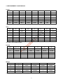
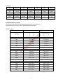
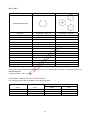
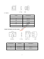
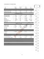
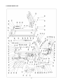
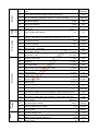
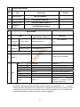
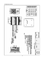
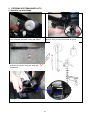
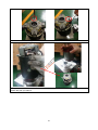
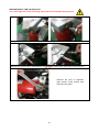
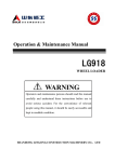
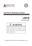
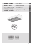
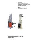
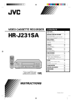
SERVICE & MAINTENANCE MANUAL Semi-Electric Stacker Version 06/2013 SPM1030 ‐SHFW‐001 CONTENT FOREWORD ............................................................................................................................................3 1. GENERAL.........................................................................................................................................4 1.1 INTRODUCTION – MAINTENANCE SAFETY PRECAUTIONS ................................................4 1.2 MEASUREMENT CONVERSIONS.............................................................................................8 2. SPECIFICATION.............................................................................................................................13 2.1 OVERVIEW ...............................................................................................................................13 2.2 SPARE PARTS LIST ................................................................................................................14 2.3 SPECIFICATION SHEET..........................................................................................................17 2.4 LUBRICATION..........................................................................................................................19 3. HYDRAULIC SYSTEM ...................................................................................................................20 3.1 OPERATION OF CYLINDER....................................................................................................20 4. ELECTRIC BOX .............................................................................................................................22 4.1 ELECTRIC DIAGRAM ..............................................................................................................22 TOOL FOR REPAIRING THE PIN OF ELECTRIC PLUG ..............................................................24 4.2 REPLACE THE ELECTRIC PARTS .........................................................................................25 4.3 BATTERY .................................................................................................................................28 4.4 CHARGER ................................................................................................................................30 4.4.1 MAIN PRODYCT SPECIFICATION .......................................................................................31 4.4.2 ENVIRONMENTAL CONDITION ...........................................................................................31 4.4.3 ELECTRICAL CHARACTERISTICS .....................................................................................31 5. STEERING SYSTEM& WHEEL KITS.............................................................................................38 5.1 CONTROL HANDLE.................................................................................................................38 5.2 OPERATION OF THE WHEEL .................................................................................................39 5.2.1 OPERATION OF THE BIG WHEEL (LEFT) ..........................................................................39 5.2.2 OPERATION OF THE FOOTBREAK ....................................................................................40 5.2.3 OPERATION OF THE LOADING ROLLER...........................................................................41 6. POWER PUMP UNIT ......................................................................................................................42 4.3 CLEAN OIL TANK AND FILTER..............................................................................................44 7. MAINTENANCE CHECK LIST .......................................................................................................51 7.1 HYDRAULIC OIL ......................................................................................................................51 7.2 REGULAR MAINTENANCE .....................................................................................................51 7.3 LUBRICATION..........................................................................................................................51 7.4 HOW TO CHARGE STORAGE BATTERY ..............................................................................51 8. TROUBLE SHOOTING...................................................................................................................52 2 FOREWORD Proper operation, maintenance, troubleshooting and repairs are necessary to preserve the performance of the pallet truck over a long period and ensure that fault and breakdowns do not occur. The purpose of this service manual is to provide necessary information especially in inspections, repair and maintenance. The majority of this pallet truck consists of steel, it can be completely recycled. Waste material in conjunction with repairs, maintenance, cleaning or scrapping, must be collected and disposed of in an environment-friendly way and in accordance with the directives of respective countries. Such work must be carried out in areas intended for this purpose. Recyclable material should be taken care of specialized authorities. Environmentally hazardous waste, such as oil filters, batteries and electronics, will have a negative effect on the environment or health, if handled incorrectly. All of the information reported herein is based on data available at the moment of printing. Our products are constantly being developed and renewed, we reserves the right to modify our own products at any moment without prior notice and incurring in any sanction. So, it is suggested to always verify possible updates. 3 1. GENERAL 1.1 INTRODUCTION – MAINTENANCE SAFETY PRECAUTIONS Maintenance work may cause injuries. Always take care to perform work safe, at least observing the following. It is of utmost importance that maintenance personnel pay strict attention to these warnings and precautions to avoid possible injury to themselves, others or damage to the equipment. A maintenance program must be followed to ensure that the machine is safe to operate. The specific precautions to be observed during maintenance are inserted at the appropriate point in the manual. These precautions are, for the most parts, those that apply when servicing hydraulic and larger truck component parts. MODIFICATION OF THE TRUCK WITHOUT CERTIFICATION BY A RESPONSIBLE AUTHORITY THAT THE TRUCK IS AT LEAST AS SAFE AS ORIGINALLY MANUFACTURED, IS A SAFETY VIOLATION. SINCE THE TRUCK MANUFACTURER HAS NO DIRECT CONTROL OVER THE FIELD INSPECTION AND MAINTENANCE, SAFETY IN THIS AREA RESPONSIBIUTY OF THE OWNER OR OPERATOR. FAILURE TO COMPLY WITH SAFETY PRECAUTIONS, LlSTED IN THIS SECTION MAY RESULT IN MACHINE DAMAGE, PERSONNEL INJURY OR DEATH AND IS A SAFETY VIOLATION. When carrying out any operation or maintenance, have trained and experienced personnel to carry out the work. When carrying out any operation or maintenance, carefully read operation and maintenance handbook. Read all the precautions given on the decals which are fixed to the truck. Be sure you fully understand the content of the operation. It is important to prepare necessary tools and parts for maintain the truck. Your safety, and that of others, is the first consideration when engaging in the maintenance of equipment. Always be conscious of weight. Never attempt to move heavy parts without the aid of a mechanical device. Do not allow heavy objects to rest in an unstable position. When raising a portion of the equipment, ensure that adequate support is provided. 4 It should be noted that the machines hydraulic systems operate at extremely high potentially dangerous pressures. Every effort should be made to relieve any system pressure prior to disconnecting or removing any portion of the system. Relieve system pressure by cycling the applicable control several times with the engine(motor) stopped and ignition on, to direct any line pressure back into the reservoir. Pressure feed lines to system components can then be disconnected with minimal fluid loss. Remove all rings, watches and jewelry when performing any maintenance. Wear well-fitting helmet, safety shoes and working Clothes When drilling grinding or hammering always. Wear protective goggles. Always do up safety clothes properly so that they do. Not catch on protruding parts of machines. Do not wear oily clothes. When checking, always release battery plug. DO NOT WEAR LONG HAIR UNRESTRAINED, OR LOOSE-FITTING CLOTHING AND NECKTIES WHICH ARE APT TO BECOME CAUGHT ON OR ENTANGLED IN EQUIPMENT. During maintenance do not allow any unauthorized person, to stand near the machine. Flames should never be used instead of lamps. Never use a naked flame to check leaks or the level of oil or electrolyte. Immediately remove any oil or grease on the floor of the operator’s compartment or on the handrail. It is very dangerous if someone slips while on the machine. Always use pure oil or grease, and be sure to use clean containers. Oil is a dangerous substance. Never handle oil, grease or oily clothes in places where there is any fire or flame. As preparation for use of fire extinguishers and other fire- fighting equipment. Keep the battery away from fire hazards. The generated gases are explosive. Store all the oils in a specified place. Keep the flammable things away from the machine. Do not smoke at the working place. Battery should always be disconnected during replacement of electrical components. 5 Always use the grades of grease and oil recommended by NOBLELIFT choose the viscosity specified for the ambient temperature. Exhaust gas is dangerous provide ventilation when working in a closed space. Avoid breathing dust that may be generated when handling components containing asbestos fibers. Wear a gas mask if necessary. When working on top of the machine, be careful not to lose your balance and fall. Hand a caution sign in the operator’s compartment (for example “Do not start” of “Maintenance in progress”). This will prevent anyone from starting or moving the machine by mistake. When welding on the machine or working on the electrical system, ALWAYS turn the key switch OFF and remove the battery plug from the battery. Park the machine on firm, flat ground. Lower the fork to the min. height and stop the motor. Sulfuric acid in battery electrolyte is poisonous. It is strong enough to burn skin and eat holes in clothing. If you spill acid on your clothes or skin, immediately flush with large quantities or water. When working on the battery, wear goggles or safety glasses. If splashed into the eyes, flush with water and get medical attention immediately. Battery terminals touched by metal objects can cause short circuit and burn you. Keep tools away from the terminals. Keep sparks, lighted matches, and open flame away from the top of battery. Battery (hydrogen) gas can explode. When disassembling and assembling the battery, make sure that the battery terminals (+, –) are correctly connected. If water gets into the electrical system, abnormal operation or failure can result. Do not use water or steam on sensors, connectors and instruments in the cab. 6 Do not handle electrical equipment while wearing wet gloves, or in wet places, as this can cause electric shock. When working with other, choose a group leader and work according to his instructions. Do not perform any maintenance beyond the agreed work. Unless you have special instructions to the contrary, maintenance should always be carried out with the motor stopped. If maintenance is carried out with the motor running, there must be two technicians present: One operating the stacker and the other one performing the maintenance. In such a case, never touch any moving part. Before making adjustment, lubricating or performing any other maintenance, shut off all power controls. When removing parts containing O-ring Gaskets or seal clean the mounting surface and replace with new sealing parts. Thoroughly clean the machine. In particular, be careful to clean the grease fittings and the area around the dipsticks. Be careful not to let any dirt or dust into the system. Use only approved nonflammable cleaning solvents. When changing the oil or fitter, check the drained oil and filter for any signs of excessive metal particles or other foreign materials. Always use NOBLELIFT genuine parts for replacement. ENSURE REPLACEMENT PARTS OR COMPONENTS ARE IDENTICAL OR EQUIVALENT TO ORIGINAL PARTS OR COMPONENTS. When checking an open gear case, there is a risk of dripping things in. Before removing the covers to inspect such cases, empty everything from your pockets. Be particularly careful to remove wrenches and nuts. 7 1.2 MEASUREMENT CONVERSIONS Length Unit cm m km in ft yd mile cm 1 0.01 0.00001 0.3937 0.03281 0.01094 0.000006 m 100 1 0.001 39.37 3.2808 1.0936 0.00062 km 100000 1000 1 39370.7 3280.8 1093.6 0.62137 in 2.54 0.0254 0.000025 1 0.08333 0.02777 0.000015 ft 30.48 0.3048 0.000304 12 1 0.3333 0.000189 yd 91.44 0.9144 0.000914 36 3 1 0.000568 mile 160930 1609.3 1.6093 63360 5280 1760 1 1mm=0.1cm, 1m=0.001mm Area Unit cm2 m2 km2 a ft2 yd2 in2 cm2 1 0.0001 – 0.000001 0.001076 0.000012 0.155000 m2 10000 1 0.000001 0.01 10.764 1.1958 1550.000 km2 – 1000000 1 10000 1076400 1195800 – a 0.01 100 0.0001 1 1076.4 119.58 – ft2 – 0.092903 – 0.000929 1 0.1111 144.000 yd2 – 0.83613 – 0.008361 9 1 1296.00 in2 6.4516 0.000645 – – 0.006943 0.000771 1 1ha=100a, 1mile2=259ha=2.59km2 Volume Unit cm3 = cc m3 l in3 ft3 yd3 cm3 = m l 1 0.000001 0.001 0.061024 0.000035 0.000001 m3 1000000 1 1000 61024 35.315 1.30796 l 1000 0.001 1 61.024 0.035315 0.001308 in3 16.387 0.000016 0.01638 1 0.000578 0.000021 ft3 28316.8 0.028317 28.317 1728 1 0.03704 yd3 764529.8 0.76453 764.53 46656 27 1 1gal(US)=3785.41 cm3=231 in3=0.83267gal(US) Weight Unit g kg t oz lb g 1 0.001 0.000001 0.03527 0.0022 kg 1000 10 0.001 35.273 2.20459 t 1000000 1000 1 35273 2204.59 oz 28.3495 0.02835 0.000028 1 0.0625 lb 453.592 0.45359 0.000454 16 1 1 tone (metric)= 1.1023 ton(US)=0.9842 ton(UK) 8 Pressure Unit kgf/cm2 bar Pa=N/m2 kPa lbf/in2 lbf/ft2 kgf/cm2 1 0.98067 98066.5 98.0665 14.2233 2048.16 bar 1.01972 1 100000 100 14.5037 2088.6 Pa=N/m2 0.00001 0.001 1 0.001 0.00015 0.02086 kPa 0.01020 0.01 1000 1 0.14504 20.886 lbf/in2 0.07032 0.0689 6894.76 6.89476 1 144 lbf/ft2 0.00047 0.00047 47.88028 0.04788 0.00694 1 kgf/cm2=735.56 Torr(mmHg)=0.96784atm Standard tightening torque The following charts give the standard tightening torques of bolts and nuts. Exceptions are given in sections of “Disassembly and Assembly” METER TABLE Classification 4T, 5T 10T 10.9 Bolt type Bolt size Torque kgf · m (lbf · ft) Torque kgf · m (lbf · ft) M4 0.2 ± 0.02 0.4 ± 0.04 M5 0.3 ± 0.03 0.8 ± 0.08 M6 0.5 ± 0.05 1.4 ± 0.14 M8 1.2 ± 0.12 3.3 ± 0.3 M10 2.3 ± 0.23 6.5 ± 0.7 M12 4.0 ± 0.4 11.3 ± 1.1 M14 6.4 ± 0.6 17.9 ± 1.8 M16 9.5 ± 0.9 26.7 ± 2.7 M18 13.5 ± 1.4 38.0 ± 3.8 M20 18.6 ± 1.9 52.2 ± 5.2 M22 24.7 ± 2.5 69.4 ± 6.9 M24 32.1 ± 3.2 90.2 ± 9.0 M30 62.6 ± 6.3 176.1 ± 17.6 M36 108.2 ± 10.8 304.3 ± 30.4 M42 171.8 ± 17.2 483.2 ± 48.3 M45 211.3 ± 21.1 594.3 ± 50.4 9 INCH TABLE 4T, 5T 10T Bolt size Torque kgf · m (lbf · ft) Torque kgf · m (lbf · ft) 1/4 0.6 ± 0.06 1.7 ± 0.2 5/16 1.2 ± 0.12 3.0 ± 0.3 3/8 2.0 ± 0.20 5.6 ± 0.5 7/16 3.2 ± 0.32 8.9 ± 0.9 1/2 4.7 ± 0.47 13.4 ± 1.3 9/16 6.8 ± 0.68 19.0 ± 1.9 5/8 9.3 ± 0.93 26.1 ± 2.6 3/4 16.0 ± 1.60 45.1 ± 4.5 7/8 25.5 ± 2.55 71.6 ± 7.2 1 38.0 ± 3.80 106.9 ± 10.7 1-1/8 54.1 ± 5.41 152.2 ± 15.2 1-1/4 74.2 ± 7.42 208.9 ± 20.9 1-3/4 98.8 ± 9.88 277.8 ± 27.8 1-1/2 128.2 ± 12.82 360.7 ± 36.1 Classification Bolt type The torque in above table shall not be applied to nylon or nonferrous bolts or washer. The same is valid for not standardized ones. H Newton meter : 1 Nm = 0.1kgfm TIGHTENING TORQUE OF SPLIT FLANGE BOLTS The following torque shall be applied to the split flange bolts. Diameter Flat width Torque (mm) (mm) kgf·m N·m 10 14 6.7 ± 0.7 66.7 ± 6.8 12 17 11.5 ± 1 112 ± 9.8 16 22 28.5 ± 3 279 ± 29 10 O – ring Plug PF THREAD Thread Torque (kgf·m) 1/8 1.1 ± 0.1 1/4 2.6 ± 0.2 3/8 4.6 ± 0.3 1/2 8.5 ± 0.4 3/4 19 ± 1.0 1 33 ± 2.0 TORQUE FOR SWIVEL NUT WITH O-RING Connector O – ring Swivel – nut Tube O.D (inch) Thread (in) Torque (kgf·m) 1/2 UN 13/16 - 16 9.5 ± 0.95 3/4 UN 1 3/16 - 12 18 ± 1.8 1 UN 1 7/16 - 12 21 ± 2.1 11 hose APPROXIMATE CONVERSIONS SI Unit Conv Factor 0.113 1.36 7.22 × × × × × × × × × × × × × × 0.249 3.38 6.89 0.069 0.070 0.069 0.00689 = kPa = kPa = kPa = bar* = k f/ 2* = bar* = MPa × × × × Power r (W = J/s) 1.36 = PS (cv) 1.34 = HP 0.948 = Btu/s 0.74 = ft·lb/s × × × × 0.736 0.746 1.055 1.36 = = = = kW kW kW W × 1.055 × 4.19 = = kJ J kiloPascal (kPa) kiloPascal (kPa) kiloPascal (kPa) (bar) (kg/cm2) Newton/mm2 MegaPascal (MPa) (Pa=N·m2) Energy (J = N·m) × 0.948 = Btu × 0.239 = calorie kiloJoule (kJ) Joule (J) (J=N·m) SI Unit × × × × × × 8.9 0.74 0.102 Conv Factor = ln·in = lb·ft. = kg·m Pressure (Pa = N/m2) 4.0 = in. H2O 0.30 = in. Hg 0.145 = psi 14.5 = psi 14.22 = psi 145.04 = psi 145 = psi Newton meter (N·m) Newton meter (N·m) Newton meter (N·m) kiloWatt (kW) kiloWatt (kW) kiloWatt (kW) Watt (W) (W=J/s) Non–SI Unit Torque = = = Velocity and Acceleration ×3.28 × 0.305 meter per sec (m/s ) = ft/s2 = × 3.28 × 0.305 meter per sec (m/s) = ft/s = × 1.61 kilometer per hour (km/h) × 0.62 = mph = Horse Power/Torque BHP × 5252 R.P.M. = TQ (lb·ft) TQ Z R.P.M. 5252 = B.H.P. Temperature °C = (°F–32) ÷ 1.8 °F= (°C Z 1.8) + 32 Flow Rate 3 × 0.264 liter/min (dm /min) = US gal/minZ3.785 = Note : ( ) Non–SI Unit 2 2 12 N·m N·m lb·ft.* m/s2 m/s km/h l/min 2. SPECIFICATION 2.1 OVERVIEW 1 Hydraulic system 2 Electric box 3 Steering system& wheel kits 4 Power pump unit 5 Fork carriage 6 Mast system 13 2.2 SPARE PARTS LIST 14 No. 101 102 103 104 105 106 107 109 111 112 113 114 115 116 117 118 119 120 121 122 123 124 125 126 127 128 129 130 131 133 134 135 136 137 137A 138 138A 139 140 141 142 143 144 145 146 147 148 149 150 151 151A 153 155 156 157 Description Inner Mast (2.5G) Inner Mast (3.0G) Locking Ring Bearing Roller For Chain Locking Ring Screw Washer Roller Bolt Bolt Crutch of Idler Pulley Shaft Idler Pulley Locking Ring Mast (2.5G) Mast (3.0G) Hoop Nut Bolt Nut Protecting Meshwork (2.5G) Protecting Meshwork (3.0G) Protecting Washer Washer Bolt Handle Cover Charger Urgent Switch Pump Station Voltage Meter Bolt Battery Bolt Cap Bearing Bearing Bearing Bearing Seat of Wheel Draw-Bar for Turning Gas spring Locking Ring Seat of gas spring Hoop Bolt Shaft Bolt Shaft Seat of Draw-Bar Bolt Washer Washer Chain Washer Nut Foot Plate Qty. 1 1 2 2 2 2 1 8 8 2 6 2 2 2 2 1 1 1 4 1 2 1 1 4 4 4 2 1 1 1 1 1 4 1 2 2 1 2 1 2 1 1 1 1 1 1 2 1 1 1 1 1 1 1 1 1 1 1 No. 158 159 160 161 162 163 163A 164 165 166 167 168 169 170 171 172 173 174 175 176 180 181 182 184 185 186 187 188 192 193 194 195 195A 196 197 198 199 200 201 202 203 204 205 207 208 210 211 212 213 214 215 216 217 218 219 16 Description Locking Ring Shaft Brake Spring Bolt Sprocket Wheel Sprocket Wheel Seat of Turning Wheel Big Wheel Bearing Oil holder Washer Locking Nut Axle for wheel Loading Roller Bearing Washer Shaft Linking Plate Elastic Pin Fork Carriage Nut Link bolt Split pin Chain (2.5G) Chain (3.0G) O-Ring Body of Valve Safty valve Seal Washer Elbow Bend Pipe Bolt for pipe Seal washer Cylinder: for lifting height 2.5m Cylinder: for lifting height 3.0m Sleeve Dust Ring Screw cover Piston rod: for lifting height 2.5m Piston rod: for lifting height 3.0m Piston O-Ring O-Ring Y ring Guide rings Nut Connect shank Round cover Washer Nut Elastic washer Key switch (with key) Bolt Protecting Cover Bolt Oil holder Washer Qty. 1 1 1 1 1 1 1 1 2 4 2 2 2 2 4 8 8 4 4 8 1 4 2 2 2 2 1 1 1 1 1 1 1 2 1 1 1 1 1 1 1 1 2 1 1 1 1 1 1 4 1 4 1 2 2 8 2 2 2.3 SPECIFICATION SHEET 2.3.1 RESIDUAL CAPACITY AT DIFFERENT LIFTING HEIGHT Lifting height h3 mm Actual load capacity 1500 1000 500 2500 1000 400 3000 600 300 600 800 Load center distance mm (C) 2.3.2 FEATURE ( Q ) kg TECHNICAL 17 ht Features Weig Tyres, chassis Dimensions Performan ce data Motor 1.2 Type 1.3 Power: electric (battery), diesel, gasoline, gas, hand 1.4 Driving mode(hand, pedestrian, stand-on, sit-down, unit-pick) 1.5 Rated load capacity Q (kg) 1000 1.6 Load center distance c (mm) 600 1.9 Wheelbase 2.1 SPM1030( Hand Pedestrian y (mm) Service weight (with battery) 1210 kg 430 3.1 Tire type: solid rubber, high-performance elastomer, nylon, PU Nylon/ PU 3.2 Tyre size, drive size mm 180x50 3.3 Tyre size, load size mm 74x70 3.5 Wheel number (front/rear) 3.6 Wheel track (front) b10 (mm) 3.7 Wheel track (rear) b11 (mm) 4.2 Enclosed mast height 4.4 Lift height h3 (mm) 3000 4.5 Max. mast height h4 (mm) 3570 4.9 Height of tiller in drive position min. /max. h14 (mm) 790/1156 4.15 Height, lowered h13 (mm) 85 4.19 Overall length L1 (mm) 1720/1580 4.20 Length to face of forks L2 (mm) 610/670 4.21 Overall width b1 (mm) 4.22 Fork dimensions 4.25 Distance between fork arms 4.33 Aisle width for pallets 1000×1200 lengthway (1200 placed along fork) 4.34 Aisle width for pallets 800×1200 lengthway (1200 placed along fork ) 4.35 Turning radius 5.2 Lift speed, laden/ unladen 5.3 Lowering speed, laden/ unladen 5.11 Service brake 6.2 Lift motor rating at 15% 6.4 Battery voltage/ nominal capacity K5 6.5 Battery weight 2/4 h1 (mm) s/e/L (mm) b5 (mm) 680 400/490 2080 777 60/180/110 0 570 330~640 2230 2175 Wa (mm) mm/s mm/s 1400 90/140 120/100 Manuel kw V/Ah kg 18 1.5 12/150 45 2.4 LUBRICATION Hydraulic oil Hydraulic oil must have anti-wear qualities at least. It is not advisable to mix oils of different brands or types, as the may not contain the same required additives or be of comparable viscosities. Name: Thickened hydraulic oil. ISO Viscosity Grade Characteristics At 40OC Viscosity At 50OC Viscosity index Flash point, Cleveland open cup Pour point, Max Density at 15 OC Copper corrosion(100OC, 3h) Foaming (93.5 OC) Vickers vane pump test, loss of mass (on vanes after 100h) Diameter of wear spot, 1200 r/min, 294N, 30min, 75 OC #40 #30 57 40 ≥150 ≥160 ≤-35 48 30 ≥150 ≥160 ≤-35 861.5 ≤1 ≤30/0 15.3 ≤0.5 unit mm2/s O C C kg/m3 degree ml / ml mg mm O ≤1 ≤30/0 ≤100 ≤0.5 The oil for gear box Name: Extreme pressure lithium-based grease, 1#. Characteristics unit Worked Penetration, 0.1mm 310--340 Dropping point, O ≥170 N ≥177 Pa.s ≤250 Grade 1 % ≤10 C Extreme pressure (Timken OK) O -1 Similar viscosity (-10 C, 10s ) O Corrosion preventive properties (52 C, 48h) O Wire points oil (100 C, 24h) 19 3. HYDRAULIC SYSTEM 3.1 OPERATION OF CYLINDER STRUCTURE Remove 8 screws on the protecting meshwork and remove it Remove 2 dome cap nuts and 2 hexagon nuts with wrench 20 Now you can take away the hoop fixing the cylinder Remove the screw of the hydraulic pipe lift the fork up to a certain height and support the inner mast with a stick Remove the screw on the seat for chain The oil will spill over when removing; keep clean for the stacker and yourself! Press the Piston rod hard so that it can apart from the seat Now you can remove the cylinder and replace it. 21 4. ELECTRIC BOX 4.1 ELECTRIC DIAGRAM WIRING DIAGRAM Electric diagram SPM 10 No. Parts No. Code 1 DQ-40 XW 2 DQ-108 U 3 DQ-110 HL 4 DQ-105 GB 5 DQ-106 S 6 DQ-46 FU1 7 KMp Model Other Description Qty. 1 Alternative 3×0.75 Plug 12V/20A QQE240-5CH20-26-A 1 Alternative Charger 1 Inside Light of charger 12V/150Ah 1 Battery ZDK31-250 1 Power switch 200A 1 Fuse 200A DC12V 1 Pump Relay for motor 1.5Kw 1 Pump Motor 1 6×30 6A Fuse CNL-6A 1N5408 2 Diodes LKS-101A 1 Key switch 12V BL1201A(B) 1 Battery indicator 8 WG-98T Mp 9 DQ-111 FU2 10 DQ-10 VD 11 DQ-39-2 SY 12 DQ-113 P 13 DQ-114 B Module S Micro switch 14 BD-V-12 1 1 22 Pump CABLE SYSTEM 23 4.2 TOOL FOR REPAIRING THE PIN OF ELECTRIC PLUG No. Application Figure 1 Tool for removal of pins / sleeves 2 Tool for application of pins / sleeves 3 Tool for release of lock 4 Tool for application of secondary locking 2 – pole 5 Tool for application of secondary locking 4 – pole 6 Tool for removal of pins / sleeves 24 4.3 REPLACE THE ELECTRIC PARTS Switch off electrical power before repair! Remove 4 screws (each 2 on left and right) on the Cover , dismantle the washer, then you can remove the cover. Turn the mushroom head of the emergency button; let the hole of the mandrill be line with the groove of the sleeve. Use a small screwdriver to insert the hole, and then turn counter-clockwise the mushroom head to remove the mushroom head. Turn counter-clockwise the head of the control stick and remove it 25 Now you can open the main cover. After dismantle the connector of charger, key switch, emergency button and battery indicator, you can remove the cover. All electric parts appear. REPLACE THE BATTERY INDICATOR Remove the 4 cables at the back of the indicator Turn counter-clockwise the screw fixing the hoop, and then you can remove the indicator from outside. 26 REPLACE THE KEY SWITCH Turn counter-clockwise the screw of key switch with wrench and then you can remove it from outside REPLACE THE EMERGENCY BUTTON After dismantle the mushroom head and main cover you can see the frame of emergency button, remove 2 screws and remove 2 cables connecting to the emergency button, then you can replace it. REPLACE THE VOLTAGE PROTECT MODULE Remove 2 screws fixing the protect module, dismantle the connector and then you can remove the protecting module 27 OPERATION OF THE MAGNETIC VALVE The Magnetic valve is a wearing part. If the forks automatically lower after lifting, the magnet valve may be blocked or damaged, remove it to clear or replace. Remove the cable 9 on the micro switch of valve, and remove cable 2 on the motor Turn counter-clockwise the fixing screw, and then you can remove the Magnetic valve and replace it 4.4 OPERATION OF THE BATTERY The size of battery is according to English BS standard. Rate Specification SPM1030 Rated voltage 12V(X1) Capacity (5 hours) 150Ah Overall size (L*W*H)(mm) 523×238×283 24A DURATION OF DISCHARGING CURVE (ENVIRONMENTAL TEMPERATURE = 25OC) 28 (min) Discharging 100% DURATION OF DISCHARGING LIFE TEST CURVE ( ENVIRONMENTAL TEMPERATURE = 25 O C) CHARGING CURVE 29 REPLACE THE BATTERY Remove the bolts, nuts, washers, which fix the power cable (+, -) to the battery. Remove the screws fixing the hoop, press the handle downward and you can remove the battery and replace it. Don’t let the wrench to touch the other pole, otherwise it will cause short-circuit. Avoid kicking by the rebound handle. 4.4 INSTRUCTION OF THE CHARGER The battery generates flammable and explosive gases during charge, so excellent ventilation is required. Open the liquid refilling cap or seal cap. Do not smoke around the battery during charge. Any fire and spark is forbidden. REPLACE THE CHARGER 30 Dismantle 2 screws fixing cable B+ and B-, and remove the connector, remove 2 screws at the bottom of the charger, then you can remove and replace it. 4.4.1 MAIN PRODYCT SPECIFICATION Max. output power Input voltage Output voltage Output current range Combined regulation 300W 115Vac/230Vac +14.7.0Vdc 19-21A ±3% 4.4.2 ENVIRONMENTAL CONDITION No. Item Technical specification 1 Humidity 5%-95% 2 Altitude ≦3000 Cooling The power supply is cooled by 80*80*25mm 12VDC ball-bearing fans Foreed air 3 Unit Remark With package m Work normally Working under full load 4.4.3 ELECTRICAL CHARACTERISTICS 1 Input characteristics No. Item Technical specification Unit 1.1 Rated input voltage 115/230 Vac 1.2 Input voltage range 90-132/180-264 Vac 1.3 AC input voltage frequency 47—63 Hz 1.4 Inrush current 1.5 Max input current Remark 115Vac/230Vac select switch ≤100 A 264Vac input/start-up in cold condition /environmental temperature is 25℃ 8 A Vin=90Vac, load 31 rated 2 Output characteristics No. Item Technical requirements Unit 2.1 Fast charge voltage 14.2 Vdc 2.2 Floating voltage 14.7 Vdc 2.3 Maintain voltage 14.7 Vdc 2.4 Constant current 20 A 2.5 Cross regulation ±3% 2.8 Power efficiency ≥80% 3 Vin=220Vac,rated load Protection characteristics No. Item 3.1 Output over voltage protection 3.2 Remark Software over voltage protection Technical requirements Remark 16 V The charger software limits the maximum output voltage to a level suitable for the connected battery system 3.3 Thermal cutback An internal temperature monitor reduce charger output power in extreme operational temperature to prevent damage 3.4 Output current limiting protection 20A 3.5 Output short circuit protection Short circuit protection should be recovery after remove the condition 3.6 Electronic reverse battery protection The charger is electronically protected permanent revers battery connection Cell short circuit timer The battery terminal voltage must excessed 10V within the first 30 minutes of charging or the battery is determined to have a short circuit and charging is terminated 3.7 Lockout 32 A @CC MODE automatically against 4 Charger(LED) indicator No. Item Status LED 1 Waiting model LED OFF ALWAYS 2 Fast charging LED(RED)ON ALWAYS 3 Floating charge 4 Completely Charge LED(YELLOW)ON ALWAYS LED(GREEN)ON ALWAYS 5 Safety & EMC No. Item 1 Electric strength test 2 Isolation resistance 3 Leakage current 4 SAFETY 5 Remark EMC Standard (or testing condition) Input—output 1500Vac/10mA/1min Input—ground ≥10MΩ@500Vdc Output—ground ≥10MΩ@500Vdc <3.5mA Remark No breakdown Vin=264Vac,50—60Hz Comply with CE standard RE CLASS B EN55014 CE CLASS B EN55014 Air discharge LEVEL 3 EN61000-4-2(discrimination B) Contact discharge LEVEL 3 EN61000-4-2(discrimination B) RS LEVEL 3 EN61000-4-6(discrimination A) CS LEVEL 3 EN61000-4-3(discriminationA) EFT LEVEL 3 EN61000-4-4 (discrimination B) LEVEL 3 EN61000-4-5, differential module 1 KV, common module 2KV(discriminationB) Surge Remark: discrimination A— function OK under technical requirement range; discrimination B--function temporarily debasement without reposition and halt is allowed; discrimination R-- physical damage or failure of equipment are not allowed, but damage of protection device (fuse) caused by interference signal of outside is allowed, and the whole equipment can work normally after replacement of protection device and reset of running parameter. 33 6 No. Environmental testing requirements Item Technical specification Remark 1 High temperature ambient operating +40℃ Features ok 2 Low temperature ambient operating -10℃ Features ok 3 High temperature storage +70℃ Work normally after recovery under normal temperature for two hours 4 Low temperature storage -40℃ Work normally after recovery under normal temperature for two hours 5 Random Vibration 20Hz to 2000Hz 3Grms 20hours per axis 6 Repetitive Shock 40g peak 3 orthogonal axes,3+ and 3- in each axis ,11ms Pulse width 7 Thermal shock: -35℃ to +75℃,<3minute transition,2.5hour dwell,200cycle 8 Drop test: BS EN60068-2-32:1993 Ed:Free fall,appendix B Test 7. Mechanical characteristics Outline dimension(Unit:mm)length×width×height=150×150×87 Tolerance of outline dimension is ±0.5mm,others are ±0.2mm in the diagram; 1)、Input terminator diagram & definition 34 2)、 Output terminator diagram & definition: 3)、WEIGHT: (ABOUT 1.25Kg) 8. Package, transportation & storage 1)、Package There are product name, model, making of manufacturer, safety approval, and manufacturing date on the package box, and manual of specifications and packing list in the package box. 2)、Transportation Suit for transportation by truck,ship,and plane. The products should be shielded by tent from sunshine, and loaded and unloaded carefully. 3)、Storage Products should be stored in package box when it is not used. And warehouse temperature should be -40℃—+70℃, and relative humidity is 5%—95%. In the warehouse, there should not be harmful gas, inflammable, explosive products, and corrosive chemical products, and strong mechanical vibration, shock and strong magnetic field affection. The package box should be over ground at least 20cm height, and 50cm away from wall, thermal source, and vent. Under this requirement, product has 2 years of storage period, and should be rechecked when over 2 years. 9. Reliability requirements 1)、Reliability MTBF(standard, environmental temperature, load requirement)≥15Khour ;testing condition:25℃, full load,testing proved value. (1 year full warranty) 10. Charger wiring 1)、 A spark often on first connection of the charge to the battery terminals due to charging the internal output capacitors ,This is Normal and should not lead to undue concerm ,care should be taken to ensure the battery vent caps are closed and there are no flammable object in the vicinity of where the connection will be made 2)、The charger has been calibrated to take account of the voltage drop in the DC output cables during operation, To prevent the possibility of over or under charging of the battery it is recommended the DC output cable are connected directly to the battery without modification.QQE are able to customize cable lenghs and connections for volume customers with specific requirements 35 11. Label 12. CHARGE CURVE 36 13. Mechanical outline 37 5. STEERING SYSTEM& WHEEL KITS 5.1 REMOVE THE AIR SPRING Remove the screws fixing the protecting cover of handle, and take it away with hands Remove 2 screws under the handle with Allen wrench, then you can remove the air spring Remove the screws fixing the shaft with screwdriver 38 5.2 REMOVE THE HANDLE Strike out the shaft with hammer and puncher, and then you can remove the handle. Hold tight the punch and avoid striking by the hammer! 5.2 OPERATION OF THE WHEEL 5.2.1 OPERATION OF THE BIG WHEEL (LEFT) Support the mast with a block to keep the big wheel hanging Remove the screw on the cap, and then you can remove the cap, bearing, bolt and wheel. Remove the screw of big wheel with 2 wrenches Strike out the shaft of the big wheel, then you can replace the wheel Hold tight the punch and avoid striking by the hammer! 39 5.2.2 OPERATION OF THE FOOTBREAK Remove the Retaining ring with spring pliers Strike out the shaft, then you can remove the foot plate. Hold tight the punch and avoid striking by the hammer! Remove the bolt, you can see the spring, and then you can remove the whole brake. 40 Remove the screw on the cap, and then you can remove the cap, bearing, bolt and wheel. Now follow the steps of removing left wheel, you can remove the right wheel and the chain 5.2.3 OPERATION OF THE LOADING ROLLER Support the mast with a block to keep the loading roller hanging Strike out 4 elastic pin with hammer and puncher, remove the shaft and then you can remove the loading roller and replace it. Hold tight the punch and avoid striking by the hammer! 41 6. POWER PUMP UNIT HYDRAULIC FLOW DIAGRAM 1 Lowering valve 2 Emergency valve 3 Hydraulic cylinder 4 Control valve 5 Pump station INSPECTION OF HYDRAULIC OIL External appearance Smell Condition Measurement Clear and no discoloration Fine Fine Possible to use Clear but the color become brighter Fine Mixed with other oil Color changed like milk. Fine Mixed with air and water Separate water or replace oil. Color changed into dark brown Bad Oxidized Replace oil. Fine Mixed with other particles Use after filtering. Clear but there are small black spots Inspect the viscosity and if fine it can be continuously used Type: MD12160 Item SPM1030 Rated voltage 12V Rated output 1.6kw R.P.M 2950 rpm Rated current 200 A Rated hour 2 min. Insulation class IP Code F class Displacement 2.0cc/rec IP54 42 PUMP STATION OPERATION Remove 3 screws on the relay and 1 screw on the motor, and then remove the cables. keep the fork at the bottom, and remove the joint of the hydraulic pipe Dismantle the connector of cables 7-,5-2-,5-1-, cut off the plastic band. Remove 2 screws fixing the pump station at the back of the Electric box, and then you can remove the pump station and replace it. 43 HYDRAULIC PIPE For shocking, the joint of the hydraulic pipe and hydraulic pipe might be loosed and leak oil, so usually check and tighten it The oil will spill over when removing; keep clean for the stacker and yourself! 4.3 CLEAN OIL TANK AND FILTER The Plug Screw of port for adding oil is ventilating. When lower, the air will come out from the tank, it might take out little oil vapor. So, it might appear little oil stains on the plug. Wait a little and ensure that there is no oil leakage. Put the fork of the ground and drain out the hydraulic oil Dismantle the lid on the top of the tank ,pour out the hydraulic oil Dismantle the lid on the top of the tank, and fill the oil. 44 Remove out the pump station. Loosen the hoop Remove the oil tank Remove the suction filter Cleaning of oil tank and filter. Clean the Fix plate for valve etc. Clean up with compressed air and inspect if the filter is stopped or damaged. If the filter is stopped or damaged, replace it. Remove dust or foreign material from the tank. Then assemble them. TROUBLE DIAGNOSTICS Symptom Bubble in hydraulic oil Discoloration Abnormality and cause Measurement Mixed with air Check if there is any place where air can be entered. Tighten the loosened part again. Mixed with air and water Replace the oil. Became inferior in quality by oxidizing or mixed with other particles. Replace the oil. Remove 4 screws fixing the oil tank onto the valve plate, and then you can remove it. Remove the screw fixing the filter net, and then you can remove and replace it. 45 OPERATION OF THE CONTROL STICK After remove the screw fixing the control stick you can remove it, and then remove 4 screws to dismantle the coverplate of control stick. Loosen the screw fixing the control stick and remove it. Remove 2 screws fixing the seat of micro switch. Remove 2 screws fixing the Micro switch for lifting with screwdriver, and then you can remove and replace the micro switch. Dismantle the screw and the seat of micro switch 46 with 2 wrenches, one is for holding. After separate the seat of micro switch, remove the retaining ring on the screw with spring pliers Now you can see the spring inside and replace it. SEPARATION OF THE MOTOR OF PUMP STATION For the electric current of the Relay for the lifting motor is very big, and work continually hourly, the contact terminal of the relay is easy damaged. Please check it continually. Remove 2 screws fixing 2 cables connecting the relay and motor 47 Remove 2 screws fixing the relay onto motor and remove the relay Remove 2 screws on the top of motor, then press the tuber on the top cap and remove it, now you can see the internal parts of motor. Remove the screw fixing the carbon brush, and then remove the clip fixing it, now you can remove the carbon brush. 48 Remove 4 screws on the top plate with wrench and screwdriver. Now you can remove the stator of the motor, and then you can remove the rotor of the motor, and replace the part you want to. 49 SEPARATION OF THE VALVE PLATE The oil will spill over when removing; keep clean for the stacker and yourself! Remove one-way valve: Dismantle the screw of one-way valve with wrench and remove it. Remove flow-control valve: Dismantle the screw of flow-control valve with wrench and remove it. Remove the joint of hydraulic pipe: loosen it with wrench and remove it with hand. 50 7. MAINTENANCE CHECK LIST 7.1 HYDRAULIC OIL Check oil mass once every six mouths. Suggest to use No.32 hydraulic oil (GB11118-89), its kinematic viscosity is 32cSt when it is on 400, the total amount is about 4.0 litre. 7.2 REGULAR MAINTENANCE In order to keep an good using status, necessary check and maintenance everyday is suggested. Focusing mainly on:(1)wheels and mandrels, such as wires and rags binded on the wheels and mandrels; (2)whether the forks and the masts have deformation; (3)whether the voltage of the battery is normal and so on. After completing the work, unload the loads on the forks and lower the forks to the lowest position. 7.3 LUBRICATION Add grease or oil onto all moving parts frequently in order to lubricate. 7.4 HOW TO CHARGE STORAGE BATTERY 2.1 Charge storage battery when its voltage is less than 10 Volt. 2.2 Please check the battery liquid before charging, if it is not enough, add some distilled water. 2.3 The charging environment should be ventilated and far away from the fire. 2.4 If the stacker not use for long time, charge it for not less than two hours every week. 2.5 The voltage on the indicator should not be over 15 Volt when charging. 2.6 Do not use the stacker when charging. 51 8. TROUBLE SHOOTING Trouble No. Clause 1 The forks cannot be lifted to the maximum height The hydraulic enough 2 The forks cannot be lifted (Motor is rotary) 3 The motor cannot run. 4 The forks cannot be descended. 5 Leaks 6 The forks descend without the release valve worked. 7 The battery cannot be charged Fixing Methods oil is not Pour in the oil Without hydraulic oil The oil has impurities Fill in the oil Change the oil The urgent switch is pressed down, cut off the power The voltage is too low The connectors of electrical wire is loose The contactor of DC motor is broken Turn it clockwise, switch on the power Charge it Turn it firm Replace with a new one The piston rod or mast is deformed resulting from partial loading slanting to one side or over-loading The forks were kept in the high position for long time with piston rod bared to arise in rusting and jamming of the rod The release valve of pump is not opened Replace with a new one Keep the forks in the lowest position if not in use and pay more attention to lubricate the rod Check it, if damaged, replace with a new one Sealing parts worn or damaged Some part cracked or worn into small Replace with new ones Replace with new ones The impurities in the causes the release valve be unable to close tight Sealing parts worn damaged The release valve damaged oil to Change the oil or is Replace with new ones Replace with a new one Battery is broken The charging plug is loose Replace with a new one Turn it firm 52