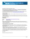
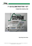
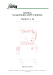
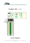
1
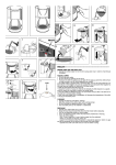
Alia
Ventilator
Alia
EXPIRATIONS-DRU CK
INSPIRATIONS-DRU CK
PLATEAU
PEEP
10
15
60
0
20
mbar
50
5
30
1
40
O2
AIR
30
30
25
25
20
20
15
15
Steriles aqua dest.
max.
10
10
5
5
2
2
M ed.
A IR
Service Instructions
Preface
Service instructions
These service instructions aim to provide assistance for troubleshooting
activities with the ALIA ventilator.
It contains drawings, circuit diagrams and parts lists for a better
understanding of how the ventilator works.
Service and maintenance work can be carried out to the peripheral
components of the ALIA ventilator. Repairs to the electronic control of
the ventilator can only be carried out by F. STEPHAN GMBH or authorized
service partners. Otherwise the entire electronic systems in the ALIA
ventilator require no maintenance.
Every step of a specific procedure should be read through carefully
before starting to service the unit. Always only use the correct tools and
the stated measuring equipment. Failure to follow the instructions and/or
recommendations in these service instructions can result in the device not
working properly or cause damage to the device.
Only use original spare parts by F. STEPHAN GMBH as contained in the
spare parts list (see chapter 10 p. 75).
Note
These service instructions do not replace the operating instructions.
Handling the device in any way presumes an exact knowledge and
compliance with the operating instructions. The device is only intended
for the described purpose.
F. Stephan GmbH
- Medizintechnik Kirchstrasse 19
56412 Gackenbach
Subject to technical alterations.
2
as of:
Januar 2006
version:
V1.0
SA-112-0106V1.0-WEM-GB
© F. Stephan GmbH
®
Contents
Contents
Contents .....................................................................................................3
1
General information ...........................................................................5
1.1
Device name and manufacturer ...............................................5
1.2
Maintenance and repairs ..........................................................5
1.3
Abbreviations and definitions..................................................6
1.4
Safety instructions ...................................................................7
2
Mechanical structure..........................................................................9
3
Components and functions...............................................................15
3.1
3.2
3.3
Sensor board..............................................................16
3.1.2
Controller board ........................................................20
3.1.3
Power Distribution Unit PDU ...................................22
Power supply .........................................................................25
3.2.1
Power supply unit......................................................26
3.2.2
Rechargeable battery .................................................27
3.2.3
Inverter ......................................................................28
Gas supply .............................................................................29
3.3.1
Oxygen supply...........................................................30
3.3.2
Compressed air supply ..............................................31
Fresh gas reservoir.................................................................32
3.5
Patient part.............................................................................36
3.5.1
PEEP valve................................................................37
3.5.2
Plateau valve .............................................................38
3.5.3
Breathing gas humidifier ...........................................38
Patient tube system ................................................................40
3.6.1
Patient tube system for adults....................................40
3.6.2
Patient tube system for children ................................42
3.6.3
Temperature sensor for patient tube system..............43
3.6.4
Pneumotachograph type D ........................................44
3.6.5
Pneumotachograph Typ C .........................................44
Serial interface .................................................................................45
4.1
© F. Stephan GmbH
3.1.1
3.4
3.6
4
Electronic controls.................................................................16
Commands .............................................................................46
SA-112-0106V1.0-WEM-GB
3
Contents
4.2
Setting and querying the date and time..................................47
4.3
Output of measured values ....................................................48
5
Tools and aids ..................................................................................51
6
Checks and maintenance..................................................................53
6.1
Every time before starting the device ....................................53
6.2
Weekly...................................................................................54
6.3
½ yearly .................................................................................55
6.4
6.3.1
½ yearly maintenance basic unit ...............................55
6.3.2
Maintenance of the patient part .................................59
Safety checks .........................................................................60
6.4.1
4
Test report .................................................................61
7
Troubleshooting ...............................................................................69
8
Annex...............................................................................................71
9
List of illustrations ...........................................................................73
10
List of tables.....................................................................................75
11
Place for your Notes.........................................................................77
SA-112-0106V1.0-WEM-GB
© F. Stephan GmbH
®
1
1
General information
1.1
Device name and manufacturer
Device name
Manufacturer
General information
ALIA
F. STEPHAN GMBH
- MEDIZINTECHNIK KIRCHSTRASSE 19
56412 GACKENBACH
(+)49 (6439) 9125 – 0
(+)49 (6439) 9125 – 111
[email protected]
www.stephan-gmbh.com
1.2
Maintenance and repairs
In the interests of device safety, maintenance of the ALIA ventilator
should be carried out every six months.
Safety checks must be carried out every six months.
Maintenance must be carried out by the authorized customer service of F.
STEPHAN GMBH.
Only spare parts from F. STEPHAN GMBH must be used during
maintenance.
Clean and disinfect the device respectively device parts every time before
maintenance, even when returning the device for repairs.
Caution!
© F. Stephan GmbH
SA-112-0106V1.0-WEM-GB
5
1
General information
1.3
Abbreviations and definitions
Abbreviation
Definition
Meaning
%h
Percentage hours
Service life of the oxygen sensor in
hours depending on the oxygen
concentration
AIR
aqua dest.
Medical compressed air
Aqua destilata (lat.)
bar
Batt
Distilled, demineralized water
Unit of measurement for compressed
air
Rechargeable battery
Device for storing electrical energy in
the form of chemical energy
cmH2O
Unit of measurement for compressed
air = mbar
FiO2
Inspired oxygen concentration
IGR
Incremental transducer
Push button and knob
PDU
Power distribution unit
Power Distribution Unit
PEEP
Positive end expiratory
pressure
V
Volt
Unit of measurement for electrical
voltage
Table 1: Abbreviations and definitions
6
SA-112-0106V1.0-WEM-GB
© F. Stephan GmbH
®
1
1.4
General information
Safety instructions
Refers to instructions drawing attention to important facts.
The following safety instructions appear at relevant points in the service
instructions and must always be heeded.
Warning
Refers to warnings which, if not heeded, can result in malfunctions,
damage or defects in the device, which can possibly also put the patient at
danger.
Refers to precautions which, if not heeded, can result in damage to the
device and its accessories.
Caution
© F. Stephan GmbH
SA-112-0106V1.0-WEM-GB
7
®
2
2
Mechanical structure
Mechanical structure
The ALIA ventilator consists of a basic housing and a front housing. The
front housing also acts as the device cover.
Fig. 1: Basic and front housing: general
Front housing
Remove the front housing to open the ALIA ventilator.
Risk of an electric shock
Disconnect from the power source before opening the housing!
Warning
The front housing is screwed to the frame with 15 countersunk screws
M4x10. The 9 screws used on the side of the device are also fitted with
rosettes to prevent damage to the plastic front housing when tightening
the screws.
Fig. 1: Opening the housing
The front housing can now be hinged open to the front.
© F. Stephan GmbH
SA-112-0106V1.0-WEM-GB
9
2
Mechanical structure
Fig. 2: Hinging open the housing
Before hinging open the front housing, ensure that the connectors for the
tube heating, the temperature sensors and the pneumotachograph have
been disconnected.
The plastic front housing is coated with an EMC varnish on the inside. It
contains the input periphery of the ALIA ventilator.
This input periphery consists of touch buttons, the IGR (push/turn knob),
the LCD display, the controller board, the double flowmeter ON/OFF
switch on the front pane.
2
1
Fig. 3: Front housing with input periphery
10
1
double flow meter
2
FiO2 and flow adjustment
SA-112-0106V1.0-WEM-GB
© F. Stephan GmbH
®
2
Basic housing
Mechanical structure
The frame of the ALIA ventilator and its reinforcement bar, fastening
bracket and panels consist of 2 mm thick powder-coated aluminium. The
bottom of the housing has a cut-out for the rechargeable battery.
1
2
3
Fig. 4: Basic housing
Service flap
1
Reinforcement bar
2
Cut-out for rechargeable battery
3
Rechargeable battery
The intake filter and oxygen sensor are located behind a service flap on
the back of the ventilator.
To open the service flap, loosen the knurled screws by turning counterclockwise.
The oxygen sensor is located on the left next to the intake filter. It is
screwed into the connection block.
It can be removed by turning counter-clockwise.
The electrical connection between the oxygen sensor and device consists
of a 2-pin AMP connector.
© F. Stephan GmbH
SA-112-0106V1.0-WEM-GB
11
2
Mechanical structure
1
3
2
Fig. 5: Service flap
1
Intake filter
2
Service flap
3
Oxygen sensor
On the left and right side wall there are recessed handles for carrying the
ALIA ventilator.
Some of the electronic controls and the power supply are accommodated
inside the ventilator.
1
2
3
Fig. 6: Electronic components
12
1
Power supply
2
Cold device connector combination
SA-112-0106V1.0-WEM-GB
3
Electronic controls
© F. Stephan GmbH
®
2
Mechanical structure
The entire pneumatic system is accommodated in the basic housing. Only
the double flowmeter is in the front housing.
The pneumatic system consists of the compressor, the fresh gas reservoir
and its control valves. The pressure switches for detecting the intake
pressure are firmly integrated in the pneumatic system
2
1
3
4
Fig. 7: pneumatic components
1
compressor
2
fresh gas reservoir
3
gas inlets
4
service flap
The patient part is connected to the basic device from the front.
The patient part is held in position by the guide rail.
© F. Stephan GmbH
SA-112-0106V1.0-WEM-GB
13
2
Mechanical structure
Fig. 8: Inserting the patient part
14
SA-112-0106V1.0-WEM-GB
© F. Stephan GmbH
®
3
3
Components and functions
Components and functions
The ALIA ventilator consists primarily of the following parts:
Electronic controls
Power supply
Gas supply
Fresh gas reservoir
Patient part
Patient tube system
Fig. 9: ALIA block diagram
© F. Stephan GmbH
SA-112-0106V1.0-WEM-GB
15
3
Components and functions
3.1
Electronic controls
The ALIA ventilator uses an 8-bit micro controller. This controls the
sensors and actuators in the system.
In addition to these components, the unit also has electronic components
which provide the electrical power supply.
These consist of a power supply unit and a device for bridging any power
failure. In the event of a power failure, the device switches over to battery
operation and regulates the battery charging process.
The sensor board generates voltages of ±15V and -5V, and the controller
board generates + 5V.
3.1.1
Sensor board
The sensor board acts as interface for triggering the actuators (control of
the fresh gas reservoir and the expiration valve) and for registering the
measured data (pressure and differential pressure sensors, AD converter).
An SPI bus system provides the link to the micro controller. This
simplifies linking the various components in terms of both hardware and
software.
The following illustration shows the components on the sensor board.
Abb. 2: Sensor board
16
SA-112-0106V1.0-WEM-GB
© F. Stephan GmbH
®
3
Main task
Voltage signals (input):
Components and functions
The main task of the sensor board is to convert the analog signals.
Rechargeable battery voltage
"DC_good" signal
On/off signal
Input voltage
12 V (for heating and valves)
Inspired pressure
Expired pressure
Flow sensor differential pressure
Oxygen sensor cell voltage
Voltage signals
(output):
Heating
Valves
"Batt_enable"
The power supply for the electronic components is generated by a
DC/DC converter on the sensor board, generating +15V, -5V and -15V.
The input signals for On/Off, DC_good, input voltage and "Batt_enable"
are sent to the SPI bus by a slide register. The input signals for pressure,
flow, O2 and battery voltage are sent to the SPI bus following
amplification and conversion via an 8-channel AD/12 bit converter.
The AD converter is equipped with protective diodes (max. 5V) on the
input side.
A serial chargeable slide register with power amplifier is used for
triggering the heating and the valves, via the SPI bus.
Pressure sensors
The respiratory pressure is measured at the inspiration fitting of the
patient part. The pressure present here is conveyed via a tube to the
pressure sensors (respiratory pressure).
For safety reasons, two pressure sensors are provided for measuring the
respiratory pressure.
The differential pressure developing over the resistance body of the PNT
head is used for measurement of the volume flow. This differential
pressure is conveyed via two tubes to the differential pressure sensor.
© F. Stephan GmbH
SA-112-0106V1.0-WEM-GB
17
3
Components and functions
1
2
3
6
4
5
Fig. 10: PNT and pressure fitting
Calibration block
1
hose heating socket
2
temperature sensor socket
3
pneumotachograph connector
4
electrical connection magnetic
coil
5
pressure fittings
6
water bath connectors
The calibration block allows for offset calibration of the differential
pressure sensor and the oxygen sensor.
The interposed solenoids V4 and V5 switch the measuring lines of the
differential pressure sensor against the atmosphere. The valves are
switched at exactly the same time. The value measured in this way
corresponds to a flow of 0 l/min.
FiO2 measurement
FiO2 measurement is carried out using an electrochemical cell (fuel cell).
This oxygen sensor generates a voltage depending on the prevailing
oxygen concentration. The voltage is then converted electronically into a
corresponding signal.
To calibrate the oxygen sensor, compressed air ( 21% O2) is blown
against it via solenoid V6. During this procedure, the display shows
"CAL" in the window of the FiO2 value. After completing calibration, the
valve switches the oxygen sensor back to the output of the double
flowmeter.
18
SA-112-0106V1.0-WEM-GB
© F. Stephan GmbH
®
3
Components and functions
Fig. 11: Display showing 'CAL'
Fig. 12: Pneumatic function diagram
© F. Stephan GmbH
SA-112-0106V1.0-WEM-GB
19
3
Components and functions
3.1.2
Controller board
1
2
Fig. 13: Controller board
1
PDU board
2
controller board
Various functional groups are accommodated on the controller board.
The figure shows the functional groups for the user interface, CPU and
interfaces.
The user interface consists of the keyboard, display (LCD) and LEDs as
input and output units for regular handling of the system. The controller
board also contains the alarm system for indicating alarm statuses.
The digital interfaces for triggering the actuators and reading the sensors
(via the sensor board) are integrated on the controller board.
20
SA-112-0106V1.0-WEM-GB
© F. Stephan GmbH
®
3
Components and functions
Fig. 14: Controller board
Main task
The main task of the controller board is to proceed with ventilation.
The procedure consists of registering the measured values of the sensor
board and calculating the values for output.
If the monitor fails, the limit values are still monitored and acoustic
alarms are produced if necessary.
The processor is an M68HC11 with external Flash ROM and RAM. The
necessary voltage of +5V is generated on the board itself (switching
regulator).
Two acoustic alarms are generated (piezo electric signal transducer,
loudspeaker) and two visual alarms.
An RS232 converter with optocoupler for electrical isolation is used for
communication with a PC.
The second RS232 converter without electrical isolation is not used on
this board.
A further task performed by the controller board is to manage the GUI
(graphical user interface).
The signals of the capacitive sensor button on the front panel and of the
incremental transducer (IGR) are read and processed by processor
M68HC11.
In addition, the graphic output is generated on the LCD.
© F. Stephan GmbH
SA-112-0106V1.0-WEM-GB
21
3
Components and functions
3.1.3
Power Distribution Unit PDU
1
Fig. 15: Power Distribution Unit PDU
1
PDU board
The task of the Power Distribution Unit PDU is to safeguard operating
voltage and the constant current charge for the rechargeable battery.
Visual and acoustic alarms are generated for error statuses.
If the output voltage of the power unit is greater than that of the battery,
then the ALIA ventilator runs completely off mains power.
If the output voltage of the power unit falls below that of the battery
(power failure, voltage fluctuations, etc.) then the ventilator runs off the
battery. This happens without electronic changeover (parallel mode).
The Power Distribution Unit PDU can only be switched on by a switched
on by a rechargeable battery. This can also be discharged (≥ 10.8 V).
22
SA-112-0106V1.0-WEM-GB
© F. Stephan GmbH
®
3
Components and functions
Fig. 16: Power Distribution Unit PDU
Tasks
Checking input voltage
Uninterrupted contactless changeover of the power supply sources
with consideration of the voltage hysteresis defined by the software
Recharging the battery
Battery test under partial load
Visual LED test when ALIA starts up
Testing the piezo electrical signal transducer when ALIA starts up
Switching the compressor on and off
Communication with the micro controller
Checking the external air pressure supply
Voltage changeover
Changeover of the various voltages takes place without any contact.
The current voltage source is indicated by the LEDs on the front of the
unit.
The charge status of the battery is shown by three coloured LEDs (red,
orange and green).
The charge curve is taken into consideration. The charge status can be
read off the LEDS:
© F. Stephan GmbH
red
= 10-40 %
orange
= 40-90 %
green
= 90-100 %
SA-112-0106V1.0-WEM-GB
23
3
Components and functions
Fig. 17: Battery display
Testing the LEDs and
the piezo
Battery test
Once the ON switch on the front of the unit has been pressed, the system
starts with a self-test which shows the user that the control elements are
functioning. The self-test consists of the following sequence:
1.
green LED of the mains power supply lights up
2.
green LED of the 12V vehicle power supply lights up
3.
green LED of the battery lights up
4.
red LED of the battery lights up
5.
piezo sounds
6.
everything goes off again
The battery test is only carried out when ALIA starts up.
The supply voltages are switched off internally for this purpose.
The test is displayed by the red and green LEDs in the battery symbol
which flash alternately.
The battery test is carried out with load on the battery by switching the
compressor on (approx. 2 amps for 6 s). This starts immediately after the
self-test. A brief alarm is given if the system does not pass the battery
test.
Total discharge
protection for the
battery
Total discharge protection comes into force when the measured voltage
of the battery is <10.8V ( Batt_enable = 0). An acoustic and visual alarm
is given.
The user should stop using the ventilator and recharge the battery, or
provide another voltage source.
Compressor ON/OFF
24
The compressor is switched on/off without any contact.
SA-112-0106V1.0-WEM-GB
© F. Stephan GmbH
®
3
Communication with
the micro controller
Components and functions
Communication with the micro controller is limited to the following
signals:
Batt_enable ( battery voltage ≥ 10.8V)
Offreq. ( signal of the ON/OFF switch)
External air pressure
supply
A pressure switch detects the external air pressure supply.
If the input pressure is < 1 bar, then the internal compressor is
automatically switched on.
If the compressor is switched off when using an external air supply, this
prolongs the battery mode.
3.2
Power supply
The integrated power supply unit is responsible for connecting the ALIA
ventilator to the mains power supply.
The cold device connector combination with integrated mains filter
supplies power to the power supply unit.
As an alternative to the mains power supply, the ALIA can be operated
from an external 12V DC voltage source.
If no external voltage source is available, the integrated rechargeable
battery is automatically used to supply power to the ventilator. The
rechargeable battery provides a backup power supply in the event of a
mains power failure.
The Power Distribution Unit controls the changeover to the provided
voltage source.
© F. Stephan GmbH
SA-112-0106V1.0-WEM-GB
25
3
Components and functions
3.2.1
Power supply unit
The ALIA ventilator is equipped with a Power supply unit in accordance
with DIN EN 60601.
1
2
Fig. 18: ALIA power supply unit
1
inverter
2
power supply unit
Input voltage:
100 – 240 V AC, 2 A, 50/60 Hz
Fuse:
2A
Output voltage:
15 V DC, 185 W
Fuse:
16 A
The output voltage of 15V DC and the DC_good signal are conveyed
directly to the Power Distribution Unit PDU.
26
SA-112-0106V1.0-WEM-GB
© F. Stephan GmbH
®
3
3.2.2
Components and functions
Rechargeable battery
The integrated rechargeable battery works parallel to the external power
supply. That means that the system changes over to battery operation
without any interruptions in the event of a mains failure.
Fig. 19: Rechargeable battery
Battery type:
Gel-type lead battery
Weight:
6.2 kg
Rated voltage:
12 V
Rated capacity:
17 Ah
Fuse:
10 A
Recharging time:
18 h
Operating time:
approx. 1 h with heating
approx. 3.5 h without heating
Connections:
© F. Stephan GmbH
threaded hole M5
SA-112-0106V1.0-WEM-GB
27
3
Components and functions
3.2.3
Inverter
The integrated clocked inverter is used only to supply power to the
internal compressor for generating compressed air.
The power supply is switched directly from the Power Distribution Unit
PDU (compressor ON/OFF).
1
Fig. 20: Inverter
1
inverter
Input voltage :
15V/DC
Output voltage:
230V/AC, 50 Hz stabilized
Continuous power:
100 W
The inverter has thermal overload protection and electronic short-circuit
protection.
28
SA-112-0106V1.0-WEM-GB
© F. Stephan GmbH
®
3
3.3
Components and functions
Gas supply
The oxygen concentration and the flow are adjusted by the double
flowmeter.
Fig. 21: Double flowmeter
This means that the ventilator can be used with just one supply gas
respectively with the internal compressor.
The output pressure is 300 mbar.
The external gas supply is provided by the coded "NIST" resp. "DIN" gas
inputs for O2 and AIR.
The gases must be dry and free of oil and dust.
© F. Stephan GmbH
SA-112-0106V1.0-WEM-GB
29
3
Components and functions
Fig. 22: Overview gas supply
3.3.1
Oxygen supply
The oxygen is conveyed to the double flowmeter through the gas input
fitting. If the input pressure is ≥ 1 bar, the oxygen failure alarm is
automatically activated.
After the ventilator has been switched on, the pressure of the oxygen
input is checked. The corresponding pressure switch is queried by the
sensor board.
If there is no pressure ( <1 bar ), the display shows the question "Is O2
available?".
Confirmation with "NO" deactivates the oxygen failure alarm!
Fig. 23: Display O2 available
30
SA-112-0106V1.0-WEM-GB
© F. Stephan GmbH
®
3
3.3.2
Components and functions
Compressed air supply
The compressed air (AIR) is conveyed to the double flowmeter through
the gas input fitting,
Pressure is constantly checked at the compressed air input. The
corresponding pressure switch is queried by the Power Distribution Unit
PDU.
The downstream pressure reducer reduces the pressure to approx. 300
mbar. The non-return valve closes the gas input while the compressor is
running.
A T-piece connects the output of the pressure reducer and the compressor
with the double flowmeter.
Compressor
If no external compressed air supply is available (input pressure <1 bar),
the compressor is automatically switched on.
The PDU board controls the compressor switching on and off.
1
Fig. 24: Compressor
1
compressor
The compressor is a maintenance-free magnetic piston pump.
The compressor runs on mains voltage.
The operating voltage for the compressor is generated by the inverter.
This guarantees operation even without the mains power supply.
© F. Stephan GmbH
SA-112-0106V1.0-WEM-GB
31
3
Components and functions
Operating pressure :
0.3 bar
Delivery volume:
30 l/min
Rated voltage :
230 V 50 Hz
Power consumption:
27 W
Max. switching-on time:
continuous operation
The compressor has a service life of 10,000 hours.
The intake (bacteria) filter is located behind the service flap of the
ventilator.
The downstream silencer reduces the noise level to less than 45 dB(A).
3.4
Fresh gas reservoir
The housing of the fresh gas reservoir consists of transparent plastic. The
bellows in the inside absorbs the fresh gas during the expiration phase in
the semi-open system. The tension springs in the bellows define the
compliance of the system.
The springs consist of stainless steel.
1
2
3
Fig. 25: Fresh gas reservoir
32
1
bellow
2
spring
SA-112-0106V1.0-WEM-GB
3
container
© F. Stephan GmbH
®
3
Components and functions
The fresh gas reservoir is only active in the semi-open mode.
It is bypassed in the open mode.
The opening at the bottom of the plastic container conveys the fresh gas
out of the unit in the case of damage to the bellows.
Filling and emptying the bellows is controlled by solenoids on the valve
block, depending on the set ventilation parameters.
1
Fig. 26: Valve block
1
© F. Stephan GmbH
valve block
SA-112-0106V1.0-WEM-GB
33
3
Components and functions
Valve block
The valve block accommodates solenoids V1 and V2 and connects them
with the connection fitting for the patient part.
1
2
Fig. 27: Valve block
1
solenoid V1
2
solenoid V2
In the open mode (constant flow), the fresh gas reservoir has no function.
Solenoid V2 remains closed permanently.
Solenoid V1 remains open permanently.
There is a constant flow of fresh gas to the patient part.
Fig. 28: Gas flow in open mode
In the semi-open mode (constant volume), solenoid V2 remains open
permanently.
34
SA-112-0106V1.0-WEM-GB
© F. Stephan GmbH
®
3
Components and functions
During the expiration phase, solenoid V1 remains closed. The bellows
fills with the constant flow of fresh gas.
During the following inspiration phase, solenoid V1 opens. The collected
fresh gas is conveyed by solenoid V1 to the patient.
The tension spring of the bellows ensures that the reservoir empties
quickly.
Fig. 29: Gas flow in semi-open mode
The safety valve in the rear wall of the basic housing prevents any
overpressure from accumulating in the bellows.
The safety valve opens at a pressure of 70 mbar.
1
Fig. 30: Safety valve
1
© F. Stephan GmbH
safety valve
SA-112-0106V1.0-WEM-GB
35
3
Components and functions
The electrical connections for the expiration valve ( PEEP valve) and the
heating of the humidifier chamber are integrated in the valve block.
A "mini-ISO" plug provides the electrical connection to the patient part.
3.5
Patient part
The patient part contains the pneumatic components of the patient circuit.
The plateau valve limits the maximum pressure and the PEEP valve
adjusts the final expiration pressure. The heating and the water bath
condition the breathing gas.
1
Fig. 31: Patient part
1
36
patient part
SA-112-0106V1.0-WEM-GB
© F. Stephan GmbH
®
3
3.5.1
Components and functions
PEEP valve
The PEEP valve consists of a valve plate on an axis. The magnetic core at
the end of the axis is wound up by a magnetic coil.
The electric resistance of the coil is approx. 120 Ω.
1
2
3
Fig. 32: PEEP valve
1
magnetic coil
2
magnetic core
3
valve disc
During the inspiration phase, the magnetic core is activated by the
controller board. The membrane at the magnetic core closes the
expiration fitting.
The PEEP valve is open in idle state.
The extent of the final expiration pressure is defined by the tension of the
spring before the valve plate. The tension in the spring is adjusted by the
PEEP knob.
© F. Stephan GmbH
SA-112-0106V1.0-WEM-GB
37
3
Components and functions
3.5.2
Plateau valve
The plateau valve consists of a valve plate with a spring before the valve
plate which limits the pressure in the patient tube system.
1
2
Fig. 33: Plateau valve
1
RLNA valve
2
plateau valve disc
The tension in the spring and thus the maximum pressure is adjusted by
the plateau knob.
RLNA valve
The valve plate contains the room air emergency breathing valve.
The silicone disk allows the patient to breathe spontaneously even if the
breathing gas should fail.
The negative pressure to be produced by the patient to open the "RLNA"
valve is approx. – 4 cmH2O.
3.5.3
Breathing gas humidifier
Heating and moistening the breathing gas is coordinated by the sensor
board. A temperature sensor in the inspiration fitting and at the end of the
heating section of the inspiration tube provide the actual temperature
value.
38
SA-112-0106V1.0-WEM-GB
© F. Stephan GmbH
®
3
Components and functions
1
2
3
4
5
6
7
Fig. 34: Patient part humidifer and sensor
1
refilling valve
5
heater tube
2
temperature sensor
6
teflon tube
3
o-ring
7
humidifier chamber
4
heating cartridge
The sensor board switches the 12V/35W heating cartridge and the tube
heating on or off depending on the nominal and actual temperature value.
The electrical resistance of the heating cartridge is 27.5 Ω.
© F. Stephan GmbH
SA-112-0106V1.0-WEM-GB
39
3
Components and functions
The water of the humidifer chamber evaporates along the heating tube.
The capacity of humidifer chamber is 500 ml
The surface of the heating cartridge heats up to more than 100 °C!
Do not touch the heating cartridge when the device is switched on!
Caution
The moistened, heated breathing air is conveyed into the patient tube
system via the inspiration fitting. The heating integrated in the tube
system prevents the water from condensing in the tube.
3.6
Patient tube system
Two different patient tube systems are to be used with the ALIA
ventilator depending on the patient.
The tube systems named here are made of silicone and are therefore
considered to be "FREE OF LATEX AND PVC".
The tube systems named here can be reused and sterilized using
conventional methods!
Please comply with chapter 8 of the ALIA operating instructions!
3.6.1
Patient tube system for adults
The patient tube system for adults consists of a Y-piece and a heated 22
mm inspiration and expiration tube.
The colour of the tube fitting for the inspiration tube is red.
It must be connected to the red tube fitting on the patient part.
The neutral coloured expiration tube is connected to the neutral coloured
tube fitting.
The continuously heated tube is 1100 mm long.
The electrical resistance of the tube heating is 26 Ω.
40
SA-112-0106V1.0-WEM-GB
© F. Stephan GmbH
®
3
Components and functions
Fig. 35: Tube system for adults
At the patient's end of the inspiration tube, the temperature sensor for
controlling the tube temperature is inserted in the tube fitting.
The patient tube system can only be operated with temperature sensor,
because otherwise the opening for the sensor would prevent any build up
of pressure!
The connectors for the heating are plugged into the corresponding sockets
on the ventilator.
Fig. 36: Heating connection
To measure the inspired or expired flow, a pneumotachograph type D
make F. STEPHAN GMBH must be used together with a patient tube
system for adults.
© F. Stephan GmbH
SA-112-0106V1.0-WEM-GB
41
3
Components and functions
3.6.2
Patient tube system for children
The patient tube system for adults consists of a Y-piece and a heated 10
mm inspiration and expiration tube.
The colour of the tube fitting for the inspiration tube is red.
It must be connected to the red tube fitting on the patient part.
The neutral coloured expiration tube is connected to the neutral coloured
tube fitting.
The tube is 1200 mm long, 800 mm of which are heated.
The electrical resistance of the tube heating is 26 Ω.
Fig. 37: Tube system for children
At the patient's end of the inspiration tube, the temperature sensor for
controlling the tube temperature is inserted in the tube fitting.
The patient tube system can only be operated with temperature sensor,
because otherwise the opening for the sensor would prevent any build up
of pressure!
The connectors for the heating are plugged into the corresponding sockets
on the ventilator.
To measure the inspired or expired flow, a pneumotachograph type C
make F. STEPHAN GMBH must be used together with a patient tube
system for children.
42
SA-112-0106V1.0-WEM-GB
© F. Stephan GmbH
®
3
3.6.3
Components and functions
Temperature sensor for patient tube system
The temperature sensor measures the temperature of the breathing gas
near to the temperature and constitutes the target parameter for
controlling the heating.
Fig. 38: Temperature sensor
The resistance of the thermistor bead integrated in the measuring tip
decreases with increasing temperature.
Temperature [°C]
Resistance [kΩ]
15
7,855
20
6,246
25
5,000
30
4,028
35
3,265
Table 1: Resistance of the temperature sensor
The temperature sensor cannot be autoclaved!
Caution
The high temperature causes cracks in the measuring bead insulation.
Penetrating water can cause short circuits in the sensor and possibly
damage the heating control!
Please comply with chapter 8 of the ALIA operating instructions!
A specially screened cable with a 5-pin "LEMOSA" plug connects the
temperature sensor to the ventilator.
This plug also connects the temperature sensor of the breathing gas
humidifier to the ventilator.
© F. Stephan GmbH
SA-112-0106V1.0-WEM-GB
43
3
Components and functions
3.6.4
Pneumotachograph type D
The pneumotachograph type D measures the inspired and expired flow
(> 25 l/min) and is used together with a patient tube system for adults.
Fig. 39: PNT D
3.6.5
Pneumotachograph Typ C
The pneumotachograph type C measures the inspired and expired flow
(> 25 l/min) and is used together with a patient tube system for children.
Fig. 40: PNT C
44
SA-112-0106V1.0-WEM-GB
© F. Stephan GmbH
®
4
4
Serial interface
Serial interface
The ALIA ventilator is equipped with a serial service and production
interface.
The device can be calibrated or subjected to fault analysis. To this end, it
must be possible to connect the ventilator to a PC with terminal program.
A NULL modem cable is used for this purpose.
For communication with the ventilator, the PC interface must be
configured as follows:
Baud rate:
19200
Data bits:
8
Parity:
none
Stop bits:
1
Flow control:
none
After the ventilator has been switched on, the interface sends the
following initialization sequence:
Fig. 41: Initialization sequence
During this phase, the controller runs through the stipulated algorithms
for the self-test.
© F. Stephan GmbH
SA-112-0106V1.0-WEM-GB
45
4
Serial interface
The test run finishes with the output "done". Now various actions can be
carried out by entering certain commands:
There is no complete syntax check of the entered commands. The user
must enter the commands correctly.
Caution
Incorrect entries can cause damage to the device!
Inputs such as "h" or "help" produce the same results by entering the first
letter "h": in this case, output consists of the version number and the list
of available commands.
4.1
Commands
cf
Input of "cf" –ENTER starts manual offset calibration of the differential
pressure sensor:
cf
Start calibration FlowCal=1 PO2Cal=0 PPatCal=0 PRedCal=0
cpr0
Input of "cpr0" –ENTER starts offset calibration of the redundant
pressure sensor:
cpr0
Start calibration FlowCal=0 PO2Cal=0 PPatCal=0 PRedCal=30
cpp0
Input of "cpp0" –ENTER starts offset calibration of the pressure sensor
near the patient:
cpp0
Start calibration FlowCal=0 PO2Cal=0 PPatCal=30 PRedCal=0
cpr5
Input of "cpr5" –ENTER starts 50 mbar calibration of the redundant
pressure sensor:
cpr5
Start calibration FlowCal=0 PO2Cal=0 PPatCal=0 PRedCal=35
cpp5
46
Input of "cpp5" –ENTER starts 50 mbar calibration of the pressure sensor
near the patient:
SA-112-0106V1.0-WEM-GB
© F. Stephan GmbH
®
4
Serial interface
cpp5
Start calibration FlowCal=0 PO2Cal=0 PPatCal=35 PRedCal=0
The new values must be saved after calibration!
To this end, adjust YES for the SAVE SETs option in the ALIA menu.
Caution
The new calibration values are only accepted after confirmation by
pressing the IGR!
Saving the values is confirmed on leaving the "Options" menu with the
output:
PCal set
4.2
Setting and querying the date and time
Input of "td" –ENTER starts the output of date and time
td
Date 15:11:22 8.12.05
Input of "td_HH:MM:SS_DD:MM:YY" –ENTER readjusts the time and
date:
ts 15:17:30 10.12.05
The system is set to 10 December 2005, 15.17 hrs and 30 seconds.
The clock in the ALIA ventilator is not buffered!
It serves merely for time recording when saving interface outputs.
© F. Stephan GmbH
SA-112-0106V1.0-WEM-GB
47
4
Serial interface
4.3
Output of measured values
The output function "out"-ENTER can be used for direct reading of the
current IO values of the ALIA ventilator. These values are shown in the
sections INTADC, EXTADC, CTRLREG and Vimage with additional
abbreviations. These act as interpretation help.
These input values are used as the basis for calculations which are shown
in the last section, broken down according to pressure, flow, O2 and
temperature.
Fig. 42: Output function "out"
INTADC
48
INTADC stands for the output values of the AD converter in the
controller board.
DPa2
= Digital value of the redundant patient pressure sensor
DO2
= Monitoring the oxygen pressure switch
UeV
= Measuring the valve flows
UeVD
= Measuring the power supply of the pressure sensors
TRed
= Digital value of the redundant temperature sensor
SA-112-0106V1.0-WEM-GB
© F. Stephan GmbH
®
4
EXTADC
Serial interface
EXTADC stands for the output values of the AD converter in the sensor
board.
DPa1
= Digital value of the patient pressure sensor
Flow
= Digital value of the differential pressure in the flow
sensor
O2%
= Digital value of the voltage in the oxygen sensor
TTank
= Digital value of the resistance in the temperature
sensor of the humidifer chamber
TTube
= Digital value of the resistance of the temperature sensor
near to the patient
Accu
CTRLREG
VImage
= Digital value of the voltage in the rechargeable battery
The register CTRLREG shows the status of the internal hardware
monitoring as digital signals.
15
= 15 V OK – voltage present
Ak
= Battery OK
DC
= 5 V supply from the power supply OK
OR
= Position of the ON/OFF switch
-
= not addressed
IV
= Expiration valve OK
H2
= Tube heating OK
H1
= Water bath heating OK
The valve image stipulates which valve is ON or OFF.
Every valve combination possible during operation of the ventilator has
its own image.
VImage indicates which combination is currently active.
The individual valves and switches are listed in the register shown below:
© F. Stephan GmbH
EV1 EV2
= Expiration valve
OV
= Calibration valve of the oxygen sensor
FV
= Calibration valve of the offset value of the differential
pressure
AE
= Battery switched on
H2
= Tube heating ON/OFF
SA-112-0106V1.0-WEM-GB
49
4
Serial interface
Pressure
H1
= Water bath heating ON/OFF
BV1
= Solenoid V1 fresh gas reservoir
BV2
= Solenoid V2 fresh gas reservoir
KE
= Compressor ON / OFF
P:
->Pat:
->Red
->O2
Current respiratory pressure in 1/10 mbar
Redundant pressure
Oxygen pressure (switch only / no measurement)
Off:
->Pat:
->Red:
->O2:
ADC offset at 0cmH2O, LSB0[0], P
ADC offset at 0cmH2O, LSB0[1], P_Red
Gain: ->Pat:
->Red:
->O2:
Flow
ADC deviation at 50 cmH2O, PGain[0]
ADC deviation at 50 cmH2O, PGain[1]
Flow
Flow in 1/10 L/min
Flow_Off
Offset ascertained at zero flow
DiffP
Differential pressure in 1/10 µbar
The displayed flow value results from the dP value calculated by means
of the differential pressure value FlowIn(ExtADC).
Temperature
Temp_Pat= 148 In= 993 R= 7944 InRed= 255 RRed=32640
TempTank= 303 In= 997 R= 3988
50
SA-112-0106V1.0-WEM-GB
© F. Stephan GmbH
®
5
5
Tools and aids
Tools and aids
The following tools and aids are required to perform servicing and
maintenance work:
Basic tools
Screwdrivers in various sizes
Phillips screwdrivers in various sizes
Wire cutting pliers
Needle nose pliers
Stripping pliers
Set of Allen keys
Scissors
Set of open-end wrenches 5.5 – 13mm
Gaspipe pliers
Soldering/unsoldering set
Tube cutter
Forceps
Brush
Special tools
PLCC extraction tool
PC with terminal program
NULL model cable
Test lung for children
Test lung for adults
Hot air fan
Lubricants/
auxiliary substances
Super Lube (silicone-based)
Berolube (oxygen-resistant grease)
Loctite (anaerobic adhesive)
Teflon sealing tape
Soldering tin
Unsoldering cord
Silicone adhesive E41 and E43
© F. Stephan GmbH
SA-112-0106V1.0-WEM-GB
51
5
Tools and aids
Instruments and
accessories
Electronic pressure meter -10 – 100 mbar / tol. ±1 digit
Oxygen monitor
Pressure measuring set consisting of injection syringe, silicone tube
3x1.5, Y-piece (small), 3-way cock
Safety tester as per VDE 0751
Vernier calliper
Measuring tape
52
SA-112-0106V1.0-WEM-GB
© F. Stephan GmbH
®
6
Checks and maintenance
6
Checks and maintenance
6.1
Every time before starting the device
The functions of the device must be checked every time before it is
started.
Device type:
SN:
WHAT
HOW
O2 spare bottle
Open bottle valve
Date:
Signature:
ACT
NOMINAL
O2 pressure
O2 > 70 bar
ALIA intake pressure 3 – 6 bar
If necessary, close bottle valve and fit a full
gas bottle.
ZGA gas connection
leads
Visual inspection of gas type colour
coding.
Note any specific inhouse ruling!
(from 30.07.2006)
Mechanical unmistakeability :
angled plug and gas connections
Iso colour code (31.12.2009 latest or
neutral colour code / gas type sticker in
place?
white
⇒ O2 (oxygen )
⇒ AIR (compressed air) black-and-white
O2
AIR
Double flowmeter
Check tightness
close all metering valves
Open O2 metering valve
Open AIR metering valve
⇒ Suspended bodies in individual measuring
tubes must return to zero
⇒ Flow of min. 30 l/min
⇒ Flow of min. 30 l/min
Power supply/
battery status
Visual inspection mains connection
⇒ Intact, strain relief in place
⇒ Mains symbol LED lights up "green"
⇒ Battery symbol LED lights up "green" or
"orange"
Device continues to operate, alarm "Power
⇒ supply fail"
Disconnect mains connection
Automatic system
test
Main switch "ON"
System test
⇒ System test successful
System tightness
Semi open = "No"
AIR flow = 4 l/min
Alarm limits Pmax 10 + 60 cmH2O
Patient part
Plateau = 50 mbar
PEEP = 3 mbar
Respiration mode CMV
Insp = 1 s
Exp = 4 s
Semi open "Yes"
⇒ Monitoring Pmax over 40 cmH2O
Inspiration pressure
(plateau)
Expiration pressure
(PEEP)
Close Y-piece
⇒ Monitoring Pmax shows adjusted
inspiration pressure
⇒ Monitoring PEEP shows adjusted
expiration pressure
Apnea monitoring
Adjust respiration form C/BKUP
⇒ After 30 s, "Apnea" alarm
© F. Stephan GmbH
⇒ Takes approx. 10 s for internal fresh gas
reservoir to fill, the monitoring Pmax over
40 cmH2O
SA-112-0106V1.0-WEM-GB
53
6
Checks and maintenance
Device type:
SN:
Date:
Signature:
ACT
WHAT
HOW
Monitoring minute
volume
Respiration mode CMV
lower limit MV to 1 L
⇒ "Low Min. Volume" alarm
Monitoring airway
pressure
Respiration mode CMV
upper limit Pmax to 40 cmH2O
Plateau 50 mbar
Disconnect Y-piece
⇒ "Peak Pressure" alarm, inspiration stops
Compress manually
⇒ Audible and visible air flow out of mask
cone
⇒ Self-filling
⇒ Bag compresses only slightly
AMBU bag
NOMINAL
Release
Close mask cone manually
⇒ "Low Pressure/Disconnected" alarm
Additions
Table 2: Test list
6.2
Weekly
Depending on the use of the ventilator, the intake filter of the integrated
compressor must be checked for soiling weekly, and replaced at the latest
after 6 months.
The intake filter is at the back of the device. Open the service flap to
remove and replace the intake filter.
1
2
Fig. 43: Back of the ALIA: service flap open
1
54
oxygen sensor
SA-112-0106V1.0-WEM-GB
2
intake filter
© F. Stephan GmbH
®
6
6.3
Checks and maintenance
½ yearly
To sustain perfect functioning of the ALIA ventilator, maintenance must
be carried out at ½ yearly intervals.
This also includes replacement of all wear parts:
6.3.1
½ yearly maintenance basic unit
O-rings and seals
In the basic ALIA device, all O-rings exposed to mechanical load must be
replaced every 6 months.
These are the O-rings at the connection fittings of the patient part, the
pneumotachograph and the seals of the connection tubes.
It is not compulsory to open the device.
Rechargeable battery
The rechargeable battery used in the ALIA ventilator must be checked for
sufficient capacity every 6 months.
It must be replaced at the latest every 3 years.
To remove the rechargeable battery, open the flap on the bottom of the
ventilator.
Fig. 44: Battery flap on the bottom of the ALIA
© F. Stephan GmbH
SA-112-0106V1.0-WEM-GB
55
6
Checks and maintenance
Caution
Oxygen sensor
When fitting the new rechargeable battery, take special care to connect it
up to the right poles! Incorrect polarity can damage the electronic
components.
The service life of the fitted oxygen sensor is approx. 150000 %h.
Check the efficiency of the sensor every six months.
To check the sensor, take it out of the device. Disconnect the connection
plug after opening the service flap.
Remove the sensor by unscrewing counter-clockwise.
The basic voltage of the fuel cell can be measured with a multimeter at
the plug of the oxygen sensor.
If the measured basic voltage is < 8.5 V, the cell is depleted and must be
replaced by a new one.
After opening the packaging, the oxygen sensor takes approx. 20 minutes
to achieve its full basic voltage.
Fluctuations in the FiO2 display are possible during this period.
The oxygen sensor has to be calibrated once it has been fitted in the
device and the service flap has been closed.
To do so, set the option O2 Cal to YES in the ALIA menu.
Please comply with chapter 3 of the ALIA operating instructions!
The new values must be saved after calibration!
To this end, set the option SAVE SETs to YES in the ALIA menu.
Caution
Intake filter
Calibrating the
pressure sensors
The new calibration value is only accepted after leaving the OPTION
menu!
Replace the intake filter of the integrated compressor every six months.
Check calibration of the pressure sensors every six months. Recalibration is only necessary if the adjusted pressure values deviate by
more than 3% from the actually achieved pressure values.
Unscrew the left recessed handle to give access to the calibration block
without opening the front housing.
56
SA-112-0106V1.0-WEM-GB
© F. Stephan GmbH
®
6
Checks and maintenance
The silicone tube fitted to the 4 mm fitting is connected directly to the
two pressure sensors for respiration pressure.
This tube can be used to apply the calibration pressures.
1
2
Fig. 45: Tube fitting for pressure calibration
1
handle
2
fitting 4 mm
Use a PC with terminal program for calibration.
Calibration consists of two steps:
1. Offset calibration (calibration the zero point)
2. Calibration at 50 mbar (stipulating the gain P(v)).
1. Offset calibration
To proceed with offset or zero point calibration, apply 0 mbar or
atmospheric pressure to both pressure sensors.
To do so, remove the silicone tube from the 4 mm fitting of the
calibration block.
Input of "cpr0" –ENTER starts offset calibration of the redundant
pressure sensor:
cpr0
Start calibration FlowCal=0 PO2Cal=0 PPatCal=0 PRedCal=30
© F. Stephan GmbH
SA-112-0106V1.0-WEM-GB
57
6
Checks and maintenance
Input of "cpp0" –ENTER starts offset calibration of the pressure sensor
near the patient:
cpp0
Start calibration FlowCal=0 PO2Cal=0 PPatCal=30 PRedCal=0
The new values for the offset must be saved after calibration!
To this end, set the option SAVE SETs to YES in the ALIA menu.
Caution
The new calibration value is only accepted after leaving the OPTION
menu!
Fig. 46: PC monitor after saving
2. Calibration at 50
mbar
Offset calibration must be carried out before calibration at 50 mbar.
For calibration at 50 mbar, connect the silicone tube at the 4 mm fitting of
the calibration block with a cross piece.
Connect the opens to a pressure source and the water column and adjust
to 50 mbar.
Input of "cpr5" –ENTER starts 50 mbar calibration of the redundant
pressure sensor:
Cpr5
Start calibration FlowCal=0 PO2Cal=0 PPatCal=0 PRedCal=35
58
SA-112-0106V1.0-WEM-GB
© F. Stephan GmbH
®
6
Checks and maintenance
Input of "cpp5" –ENTER starts 50 mbar calibration of the pressure sensor
near the patient:
Cpp5
Start calibration FlowCal=0 PO2Cal=0 PPatCal=35 PRedCal=0
The new values must be saved after calibration!
To this end, set the option SAVE SETs to YES in the ALIA menu.
Caution
6.3.2
The new calibration value is only accepted after leaving the OPTION
menu!
Maintenance of the patient part
The inductive resistance in the patient part of the ALIA device must be
checked with a multimeter at six monthly intervals. The measurement is
carried out at the two upper horizontal jacks on the patient part. If the
measured resistance is less than 115 Ω or larger than 125 Ω, then the
magnetic coil has to be replaced.
Remove the front panel of the patient part every six months. Clean all
loose accessible parts with a suitable cleaning agent, e.g. alcohol.
Fig. 47: Remove front panel of patient part
We draw attention particularly to the need for intensive cleaning of the
inner part, the coil body and the magnetic core. In the case of pronounced
wear (mechanical drive), replace the PEEP valve plate with axis and coil
core.
© F. Stephan GmbH
SA-112-0106V1.0-WEM-GB
59
6
Checks and maintenance
Warning
The magnetic core at the valve axis must be secured with an anaerobic
adhesive. The valve must close reliably and not have any contact with the
head end of the coil body.
Check that the valve spindles move easily (possibly lubricate with
silicone grease). Check that the O-rings of the valve spindles ( O-ring 12
x 1 ) are not damaged; replace if necessary.
When fitting the front panel, ensure that the springs are correctly
positioned in the spring spindle guides.
Before tightening the front panel again, check that the patient part
functions correctly. Check that the front panel fits correctly according to
its outer contour.
Finally, test the patient part with a flow of approx. 5 l and a patient tube
system with test lung at the ventilator. Control and readjust the knobs if
necessary.
Fit the plate knob in such a way that a pressure of 60 mbar is just reached
when the knob is turned right round to the right.
Fit the PEEP knob so that 10 mbar is achieved at the start of the bright
section when the knob is turned right round to the right.
6.4
Safety checks
Safety checks must be carried out every six months by F. STEPHAN
GMBH or the authorized customer service following the six-monthly
maintenance.
60
SA-112-0106V1.0-WEM-GB
© F. Stephan GmbH
®
6
6.4.1
Checks and maintenance
Test report
System name:
Alia
System type:
Ventilator
Manufacturer:
F. Stephan GmbH
Serial number:
Software version:
Serial number patient part:
PNT:
Tube system
PNT C
SN:
PNT D
SN:
:
Children
Adults
Test equipment make:
Type:
Serial number:
Remarks
Tester:
Test date:
Signature:
© F. Stephan GmbH
SA-112-0106V1.0-WEM-GB
61
6
Checks and maintenance
Visual inspection
Is the system in a perfect visual condition?
Is the nameplate complete and legible?
Is the front panel in perfect condition?
Is the marking (safety nameplate etc.) complete?
Electrical safety test
Function test
Test parameter
Criterion
Unit
PE conductor resistance
< 0.,3
Ω
Substitute system leakage
current
< 1.0
mA
System leakage current (mains < 0,1
connector turned)
mA
Result
OK
Sensor calibration (interface)
(only if calibration was carried out !)
62
Red. sensor
Offset
Gain
Pat. sensor
Offset
Gain
Flow sensor
Offset
SA-112-0106V1.0-WEM-GB
© F. Stephan GmbH
®
6
Checks and maintenance
Power supply
ON/OFF marking on on/off switch
Power on
Alarm: power supply failure (1x)
Front panel LED:
Mains
Battery
Vehicle
Power off
Alarm: power supply failure
Reset after 1 min
O2 supply
No O2 supply connected:
Is O2 available?
YES
Alarm "O2 pressure low"
Apply O2 pressure of 0.9 bar (increase slowly)
Reset alarm "O2 pressure low"
Connect O2 supply:
Is O2 available?
NO
No alarm "O2 pressure low"
Is O2 available?
YES
No alarm "O2 pressure low"
© F. Stephan GmbH
SA-112-0106V1.0-WEM-GB
63
6
Checks and maintenance
Performance and leak test
Siemens lung
PNT D
AIR = 25 l/min
SIMV
Insp = 1 s
Exp = 3 s
Semi-open
PEEP = 3 mbar
PLATEAU = 50 mbar
VT
(> 650 ml)
Alarm limits
ml
Insp = 2 s
Exp = 31 s
CMV SIMV A/CV C/BKUP ASB N/CPAP
Alarm
PEAK PRESS
STENOSIS
-
LOW
PRESS/DISCON
-
LOW MIN.
VOLUME
-
High MIN.
VOLUME
-
VT (EXP) LOW
-
APNOE
-
LED
64
no alarm
HP
Alarm sound HP
MP
Alarm sound MP
SA-112-0106V1.0-WEM-GB
© F. Stephan GmbH
®
6
AIR = 18 l/min
Backup time
Respiration
form
Checks and maintenance
2s
4s
8s
16 s
60 s
C/BKUP
ASB
Trigger
Curve = V’ – t
AIR = 18 l/min
Open
Exp = 32 s
Trigger
CMV
SIMV
A/CV
C/BKUP ASB
2 l/min
6 l/min
1 l/min (no own
trigger)
Heating
Heating on
Remove temperature sensors
T. SENSOR FAIL HUM
T. SENSOR FAIL PAT
H1 = 0, H2 = 0
Tube heating
FiO2
Tube heating
HEATING H2 FAIL
Patient part
HEATING H1 FAIL
Voltage:
mV
FiO2<18%
LOW FiO2
HIGH FiO2
CALIBRATION O2
© F. Stephan GmbH
SA-112-0106V1.0-WEM-GB
65
6
Checks and maintenance
Remove O2 cell
FiO2
Criterion
Unit
±3%
21
20 – 22
%
40
38 – 42
%
60
58 – 62
%
80
77 – 83
%
100
> 97
%
Save settings
O2 SENSOR FAIL
Results
Results
measuring
Alia
unit
OK
Results
Results
measuring
Alia
unit
OK
Results
Results
measuring
Alia
unit
OK
Save settings
Pressure measurement
PEEP
PEEP
Criterion
± digit
Unit
0
>1
mbar
2
1–3
mbar
5
4–6
mbar
10
9 – 11
mbar
Pmax
Pmax
66
Criterion
± digit
Unit
15
14 – 16
mbar
25
24 – 26
mbar
35
34 – 36
mbar
SA-112-0106V1.0-WEM-GB
© F. Stephan GmbH
®
6
Pmax
Criterion
± digit
Unit
50
49 – 51
mbar
Max.
Max. ±
digit
mbar
Checks and maintenance
Results
Results
measuring
Alia
unit
OK
Results
Results
measuring
Alia
unit
OK
Results
Results
measuring
Alia
unit
OK
Tidal volume
PNT C
VT
Criterion
± 20 %
Unit
50
40 – 60
ml
100
80 – 120
ml
PNT D
VT
© F. Stephan GmbH
Criterion
± 20 %
Unit
50
40 – 60
ml
150
120 – 180
ml
300
240 – 360
ml
500
400 – 600
ml
1000
800 –
1200
ml
1300
1040 –
1560
ml
SA-112-0106V1.0-WEM-GB
67
®
7
7
Troubleshooting
Troubleshooting
Alarm text
O2 SENSOR FAIL
Cause
Faulty calibration
Measured sensor voltage outside
the measurable range
Remedy
Calibrate sensor
Check connection lead
Sensor depleted
CALIBRATION O2
Faulty calibration
Calibrate sensor
Replace sensor
TEMP.SENSOR
Measured temperature close to
patient is outside the measurable
range
Check temperature sensor
Check sensor cable
Replace temperature sensor
Table 3: Troubleshooting table
© F. Stephan GmbH
SA-112-0106V1.0-WEM-GB
69
®
8
8
Annex
Annex
1
2
3
4
5
6
7
Fig. 48: ALIA complete modules
© F. Stephan GmbH
1
fresh gas reservoir
5
compressor
2
power supply
6
sensor and PDU board
3
valve block
7
rechargeable battery
4
patient part
SA-112-0106V1.0-WEM-GB
71
8
Annex
Fig. 49: Pneumatic diagram
72
SA-112-0106V1.0-WEM-GB
© F. Stephan GmbH
®
9
9
List of illustrations
List of illustrations
Fig. 1: Opening the housing ...................................................................... 9
Fig. 2: Hinging open the housing ............................................................ 10
Fig. 3: Front housing with input periphery ............................................. 10
Fig. 4: Basic housing............................................................................... 11
Fig. 5: Service flap .................................................................................. 12
Fig. 6: Electronic components................................................................. 12
Fig. 7: pneumatic components ................................................................ 13
Fig. 8: Inserting the patient part .............................................................. 14
Fig. 9: ALIA block diagram..................................................................... 15
Fig. 10: PNT and pressure fitting ............................................................ 18
Fig. 11: Display showing 'CAL'.............................................................. 19
Fig. 12: Pneumatic function diagram ...................................................... 19
Fig. 13: Controller board......................................................................... 20
Fig. 14: Controller board......................................................................... 21
Fig. 15: Power Distribution Unit PDU.................................................... 22
Fig. 16: Power Distribution Unit PDU.................................................... 23
Fig. 17: Battery display ........................................................................... 24
Fig. 18: ALIA power supply unit............................................................. 26
Fig. 19: Rechargeable battery ................................................................. 27
Fig. 20: Inverter....................................................................................... 28
Fig. 21: Double flowmeter ...................................................................... 29
Fig. 22: Overview gas supply.................................................................. 30
Fig. 23: Display O2 available.................................................................. 30
Fig. 24: Compressor ................................................................................ 31
Fig. 25: Fresh gas reservoir..................................................................... 32
Fig. 26: Valve block................................................................................ 33
Fig. 27: Valve block................................................................................ 34
Fig. 28: Gas flow in open mode .............................................................. 34
Fig. 29: Gas flow in semi-open mode ..................................................... 35
© F. Stephan GmbH
SA-112-0106V1.0-WEM-GB
73
9
List of illustrations
Fig. 30: Safety valve ............................................................................... 35
Fig. 31: Patient part ................................................................................. 36
Fig. 32: PEEP valve ................................................................................ 37
Fig. 33: Plateau valve.............................................................................. 38
Fig. 34: Patient part humidifer and sensor .............................................. 39
Fig. 35: Tube system for adults............................................................... 41
Fig. 36: Heating connection .................................................................... 41
Fig. 37: Tube system for children ........................................................... 42
Fig. 38: Temperature sensor.................................................................... 43
Fig. 39: PNT D........................................................................................ 44
Fig. 40: PNT C ........................................................................................ 44
Fig. 41: Initialization sequence ............................................................... 45
Fig. 42: Output function "out"................................................................. 48
Fig. 43: Back of the ALIA: service flap open.......................................... 54
Fig. 44: Battery flap on the bottom of the ALIA ..................................... 55
Fig. 45: Tube fitting for pressure calibration .......................................... 57
Fig. 46: PC monitor after saving ............................................................. 58
Fig. 47: Remove front panel of patient part ............................................ 59
Fig. 48: ALIA complete modules ............................................................ 71
Fig. 49: Pneumatic diagram .................................................................... 72
74
SA-112-0106V1.0-WEM-GB
© F. Stephan GmbH
®
10
10
List of tables
List of tables
Table 1: Abbreviations and definitions ..................................................... 6
Table 2: Test list...................................................................................... 54
Table 3: Troubleshooting table ............................................................... 69
© F. Stephan GmbH
SA-112-0106V1.0-WEM-GB
75
®
11
11
Place for your Notes
Place for your Notes
© F. Stephan GmbH
SA-112-0106V1.0-WEM-GB
77
F. Stephan GmbH
- Medizintechnik Kirchstrasse 19
56412 Gackenbach
(+)49 (6439) 9125 – 0
(+)49 (6439) 9125 – 111
[email protected]
www.stephan-gmbh.com