1
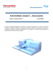
TROUBLESHOOTING 35 Problems When Sectioning Wax Embedded Specimens 35 Finesse® 325 V Vertical Tilt Control 23 W Operator Guide WARRANTY STATEMENT 40 Weight 5 WELCOME 4 A78110100 Issue 7 - English Introduction 4 Safety 4 48 A78110100 Issue 7 A78110100 Issue 7 To manoeuvre the instrument 9 SYMBOLS Weight 8 The following symbols and conventions are used throughout this manual and on the instrument. Knife Holder 14 0318 Universal Knife Holder 14 0321 Disposable Blade Holder 14 THIS SYMBOL IS USED ON THE EQUIPMENT, OR IN A DOCUMENT, TO WARN THAT INSTRUCTIONS MUST BE FOLLOWED FOR SAFE AND CORRECT OPERATION. IF THIS SYMBOL APPEARS ON THE INSTRUMENT, ALWAYS REFER TO THIS OPERATOR GUIDE. THIS SYMBOL IS USED ON THE EQUIPMENT, OR IN A DOCUMENT, TO WARN THAT THERE ARE POTENTIAL PINCH POINTS. IF THIS SYMBOL APPEARS ON THE INSTRUMENT, ALWAYS REFER TO THIS OPERATOR GUIDE. P Physical Specification 38 PRODUCT RETURN SAFETY DECLARATION 45 0322 Disposable Blade Holder 14 S To remove the knife holder 13 Safety Points 4–5 Storage 20 Section Thickness Control 22 The Specimen Clamp 13 SETTING UP To adjust the Specimen Clamp 13 Procedure 15 To fit the Specimen Clamp 13 Specimen Orientation 16 Unpacking 9 To Fit a Solid Knife 16 Battery connections 11 To remove the transit fixings 11 Knife Guards 17 To Fit Disposable Blades 18 Instrument Controls 21 Brake 21 WARNING A warning is given in the document if there is a danger of personal injury or damage to samples or equipment Note Notes give more information about a job or instruction but do not form part of the instruction Handwheel 21 Flip-Up Knife Guard 18 SPECIFICATION AND ACCESSORIES 38 Accessories Section Thickness Control 22 Accessories 39 Standard Equipment 39 K Knife Angle Lock Lever 24 Specification Electrical 38 Knife Controls 24 Environment 38 Disposable Blade Clamp 25 Indicators 38 Flip Up Knife Guard 25 Thermo Shandon Limited is an ISO 9001 and TickIT Accredited Company Knife Holder Clamp Lever 24 Finesse is a trade mark of Thermo Shandon Limited Knife Holder Clamp Lever 24 Thermo Fisher Scientific is the trading name of Thermo Shandon Limited M ® Finesse 325 meets the CE Mark requirements of the In Vitro Diagnostic Directive 98/79/EC All information contained in this manual is proprietary and confidential, and the exclusive property of Thermo Fisher Scientific. This manual is protected by copyright and any reproduction is prohibited. This manual is for use only by the individuals to which it has been made available by Thermo Fisher Scientific. Thermo Fisher Scientific makes every endeavour to ensure that the information contained in its support documentation is correct and clearly stated but does not accept responsibility for any errors or omissions. The development of Thermo products and services is continuous. Make sure that any published information that you use for reference is up to date and relates to the status of the product. If necessary, check with Thermo or your local Thermo representative. MAINTENANCE & CLEANING 31 Introduction 31 Lubrication 32 A78110100 Issue 7 Cassette Clamp 23 Specimen Controls Horizontal Tilt Control 24 Specimen Clamp 22 Cassette Clamp 23 Daily 32 Monthly 32 O OPERATION 27 Introduction 27 Sectioning 30 This manual may not, in whole or in part, be copied, photocopied, reproduced, translated, or converted to any electronic or machine readable form without prior written consent of Thermo Physical 38 Specimen Clamp 22 Vice 23 Retraction 29 © 2009 Thermo Fisher Scientific. All rights reserved. 2 Operational Parameters 38 Knife Angle Lock Lever 24 Trimming 29 Operational Parameters 38 A78110100 Issue 7 Vice 23 Tilt Clamp Lever 23 Vertical Tile Control 23 T Tilt Clamp Lever 23 TRANSPORTATION INSTRUCTIONS 42 Finesse 325 Basic Repacking Instructions 44 Finesse 325 Repacking Instructions 43 Product Return Safety Declaration 45 47 INDEX OPERATOR GUIDE LIST OF CONTENTS Symbols Warnings 26 Warning Symbol 2 Pinchpoint Warning Symbol 2 WARNING Cover To fit 11 Warning Symbol 2 To remove 10 A D Accessories 39 Debris tray - to remove 9 Standard Equipment 39 APPENDIX A - TRANSPORTATION INSTRUCTIONS 42 Declaration of Conformity 41 Decontamination 5 DESCRIPTION 6 Introduction 42 ‘Accu-Feed’ System 6 Product Return Safety Declaration 45 Coarse Advance knob 7 Knife Holders 7 B Overview 6 Battery Replacement 33 Routine Maintenance 7 Brake 10, 21 Special Design Features 7 Display 25 C Clamp Screws (Universal Knifeholder) 25 Coarse Advance Knob 22 CONTENTS 3 CONTROLS 21 Description 21 Disposable Blade Clamp 25 E Electrical Specifications 38 Environmental Specifications 38 Display 25 H Instrument Controls 21 Handwheel 21 Brake 21 Handwheel Brake - to apply 10 Handwheel 21 Horizontal Tilt Control 24 Section Thickness Control 22 Knife Controls 24 I Clamp Screws (Universal Knifeholder) 25 INDEX 46 Disposable Blade Clamp 25 Indicators 38 Flip Up Knife Guard 25 INSTALLATION INSTRUCTIONS 8 Knife Angle Lock Lever 24 Knife Holder Clamplever 24 Specimen Controls 22 3 WELCOME Safety; Unpacking; Warnings 4 DESCRIPTION Overview; Operating Principles; Construction 6 INSTALLATION AND SETTING UP General; Unpacking; Storage,Procedures; To Fit 8 CONTROLS Description; Instrument Controls; Specimen Controls; Display; Warnings 21 OPERATION Introduction; Trimming; Sectioning. 27 CLEANING AND MAINTENANCE Introduction; Lubrication; Battery 31 TROUBLESHOOTING Problems when Sectioning 35 SPECIFICATION AND ACCESSORIES 38 WARRANTY STATEMENT Declaration of Conformity 40 APPENDIX A - TRANSPORTATION INSTRUCTIONS Product Return Safety Declaration 42 INDEX 46 General 8 Access to transit fixings 10 Bench space required 8 Horizontal Tilt Control 24 Dimensions 8 Specimen Clamp 22 Siting the instrument 8 Tilt Clamp Lever 23 To fit the handwheel 12 Vertical Tilt Control 23 To lift the instrument 9 46 CONTENTS A78110100 Issue 7 A78110100 Issue 7 3 WELCOME 1 INTRODUCTION PRODUCT SAFETY DECLARATION Welcome to the Finesse 325 microtome, a precision microtome intended for use by appropriately trained Laboratory Technicians for the routine sectioning of wax or resin embedded tissue specimens that are subsequently prepared and diagnosed by a pathologist. Designed and made with care, the instrument is safe to use, simple to operate, and easy to maintain. This Operator Guide gives instructions for the correct operation and use of Finesse 325. This instrument is covered by the IVD Directive. Part 1 DECONTAMINATION CERTIFICATE Any instrument, or part of any instrument, must be clean before being returned or before any on-site service, and where necessary accompanied by a completed Decontamination Certificate. If the instrument, or any part of it, is found to be in an unclean condition upon receipt or before a service, or Thermo Fisher Scientific consider it to be a hazard, the instrument or part will be returned unrepaired at the expense of the customer or service will be refused. In the case of returns, it is important that the certificate is forwarded by post or fax, and a copy attached to the exterior of the container. Containers will not be opened until the company is in possession of the required certificate. This form MUST be completed by the customer and NOT a Thermo Fisher or distributor employee. If the instrument or any part of it is to be returned to Thermo Fisher and has been exposed to, or been in contact with potential pathogenic or radioactive material, it is essential that it is decontaminated. For decontamination, reference should be made, where appropriate, to the European Directive 2000/54/EC. To avoid any misunderstanding, we request that all instruments or parts returned to us must be accompanied by a certificate stating the following: has not been exposed to pathogenic, radioactive or other hazardous material and has been cleaned 2 SAFETY We certify that the instrument: THIS PARAGRAPH DETAILS IMPORTANT SAFETY INFORMATION. PLEASE READ THIS SECTION CAREFULLY. Model . . . . . . . . . . . . . . . . . . . . . . . . . . . . . . . . . . has been exposed to pathogenic, radioactive or other hazardous material and has been decontaminated and cleaned according to approved procedures, following exposure to: Serial No . . . . . . . . . . . . . . . . . . . . . . . . . . . . . . . . . . . . . . . . . . . . . . . . . . . . . . . . . . . . . . . . . . . . Thermo Fisher products are designed for convenient and reliable operation and to accepted standards of safety. Its use does not entail any hazard if operated in accordance with the instructions given in this manual. However, incorrect actions by a user may damage the equipment, or cause a hazard to health. It is important for you to obey the following safety precautions: Has the instrument been used for work with human, or animal, Transmissible Spongiform Encephalopathies, e.g. Creutzfeld-Jacob disease, Scrapie or BSE? YES / NO If YES, please contact Thermo Fisher Service before taking any further action. Signed . . . . . . . . . . . . . . . . . . . . . . . . . . . . . . . . . Signed . . . . . . . . . . . . . . . . . . . . . . . . . . . . . . . . . . Name (Block Capitals). . . . . . . . . . . . . . . . . . . . . . Company/Organisation . . . . . . . . . . . . . . . . . . . . . . Full address . . . . . . . . . . . . . . . . . . . . . . . . . . . . . . . . . . . . . . . . . . . . . . . . . . . . . . . . . . . . . . . . . . . . . . . i ii All users must read and understand the Operator Guide and only operate the unit in accordance with the instructions. If the instructions are not followed, then the protection provided by the instrument may be impaired. Do not modify the instrument - if unauthorised modifications are carried out, the instrument may be made unsafe and the warranty may be invalidated. iii Finesse 325 uses sharp knives. Make sure that you understand the safe and correct methods of using and handling them BEFORE you use the instrument. 4 A78110100 Issue 7 . . . . . . . . . . . . . . . . . . . . . . . . . . . . . . . . . . . . . . . . . . . . . . . . . . . . . . . . . . . . . . . . . . . . . . . . . . . Part 2 GUIDELINES FOR RETURNING INSTRUMENTS Please use the checklist (below left) to ensure that the instrument being returned is ready for collection, then fill in the details (below right). All reagents / wax removed from instrument, including vapour traps (if applicable) RMA NUMBER. . . . . . . . . . . . . . . . . . . . . Accessories are secured / itemised CARRIER. . . . . . . . . . . . . . . . . . . . . . . . . . Instrument has had transit clamps fitted as FOR ATTENTION OF. . . . . . . . . . . . . . . . . detailed in the Operator Guide Instrument is packed in original packaging .................................. Thermo Fisher Scientific, Tudor Road, Manor Park, Runcorn, WA7 1TA, United Kingdom Tel: +44 (0) 1928 534050; Fax: +44 (0) 1928 534049; www.thermo.com/pathology A78110100 Issue 7 45 1 A 3 vii Always use the knife guards provided to cover the knife when the instrument is not cutting. C B D 2 4 D C III A II A E C+D B E B I 4 Finesse FRAGILE Finesse 40kg OUTER COVER 1 6 4 5 FINESSE 325 BASIC MICROTOME REPACKING INSTRUCTIONS x2 viii It is important that normal standards of safety and good laboratory practices are employed. Always use common sense and the best known practice when operating the instrument. ix The instrument weighs approximately 40 kilograms (88 lbs); get help to move or lift it. x If the instrument has been used with materials that are toxic or contaminated with pathogenic micro-organisms, follow the cleaning instructions given in Chapter 5. The Product Return Certificate (found in Appendix A) must be completed if the instrument is to be returned to Thermo. xi The instrument should be regularly cleaned as described in Chapter 5 of this Operator Guide. xii Use only factory approved accessories or replacement parts with Finesse 325. xiii Correct maintenance procedures are essential for consistent performance. It is recommended that a Maintenance Contract is taken out with your supplier. xiv The instrument must be serviced annually by a Thermo trained engineer in accordance with the instructions contained in the Finesse 325 Service Manual (A78110101). E ss Fine GIL FRA e e ess Fin g 40k TER OU VER CO 1 xv Any problems and queries should be referred to your supplier. 44 A78110100 Issue 7 A78110100 Issue 7 5 DESCRIPTION (calibrated 1µm steps 1 - 30µm range) viii Knife Holder ix Dovetail Slider x iii xi iv Debris Tray xi Knife Angle Lock lever v xii Coarse Advance Knob xiii Horizontal Tilt Adjuster xiv Orientation Head xv Top Tray x ix viii vii vi xvi Vertical Tilt Adjuster xvii Specimen Clamp (not shown) The microtome is designed for general laboratory use and features the unique ’Accu-Feed’ system of precision advancement of the specimen without the need for adjustment. 4 5 6 FRAGILE Finesse 40kg 1 OUTER COVER Finesse 6 A78110100 Issue 7 A78110100 Issue 7 3 A 1 C x2 Note 1 Knife Holder to be ordered separately to individual preference. B A vii Section Thickness Control E ii C+D vi Knife Holder Clamp lever i A xvi B xv D xiv E xiii D C xii 4 Orientation Head Tilt Clamp Lever 4 v III iv Balanced Handwheel 2 iii Handwheel Brake I Section counter and RESET button II Available Travel Indicator ii B i FINESSE 325 BASIC MICROTOME REPACKING INSTRUCTIONS The Finesse 325 is a precision engineered rotary microtome that comprises the following main components: E GIL FR A e ess Fin g 40k TER OU VER CO 1 OVERVIEW sse Fine 1.1 43 APPENDIX A TRANSPORTATION INSTRUCTIONS A.1 INTRODUCTION If the Finesse 325 Microtome is to be serviced or returned to Thermo Fisher, it must be cleaned and decontaminated, and the Product Return Safety Declaration (see page 44) signed by the customer. If the instrument is to be transported, the transit fixings should be fitted (follow the removal instructions in Chapter 2 in reverse). Follow the diagram on page A.2 to repack the Finesse 325 for transportation. Special design features of the Finesse 325 include the facility for: i handwheel braking in any position ii specimen retraction iii section counting iv alarm annunciation at limits of travel v cutting resin or wax blocks The Finesse 325 microtome can be used with the following knife holders, in addition to a comprehensive range of accessories from our catalogue. i Low-profile disposable blade holder ii High-profile disposable blade holder iii Universal knife holder type. The Bottom Stage of the knife holder (a) accommodates both types of Thermo Fisher Top Stage, including type 0318-004, 0321-002 and 0322-002 knife holders. a The Finesse 325 microtome has the Coarse advance knob fitted towards the back of the left hand side panel of the instrument.The Coarse Advance knob turns clockwise for specimen advancement. The instrument contains electrically powered components for alarm and display purposes. These devices are powered by replaceable batteries - no mains connections are required. Routine maintenance of the Finesse 325 microtome requires only that the instrument is kept clean and is routinely lubricated with appropriate oil. Lubrication procedures are provided in Section 6.2 of this Guide. 42 A78110100 Issue 7 A78110100 Issue 7 7 INSTALLATION AND SETTING UP 2.1 GENERAL Declaration of Conformity Ensure that sufficient bench space is allocated for the Finesse 325 microtome to enable easy access to the handwheel and the specimen advance and thickness control knobs when in use. It is advisable to allow not less than 300mm (12 inches) radius of space around the instrument. This Declaration of Conformity, issued under our sole responsibility, is only valid when the instrument is used in accordance with the instructions for use. Manufacturer’s Name: Manufacturer’s Address: 300 mm Inspect the microtome on delivery and make sure that it is undamaged and complete with the components and accessories listed on the packing sheet: Rotary Microtome Product Designation: Part numbers: Finesse® 325 A78100001, A78100003, A78100005, A78100103 including accessories supplied as standard, and the following accessories 0325-105, 0325-113 Vices: Knife Holders: Year of Marking (CE): Before permanently siting the microtome make sure that the bench will hold 40 kg (88 lbs) dead weight, and will withstand rhythmic mechanical movement of the handwheel. The maximum overall dimensions of the Finesse 325 are: Tudor Road, Manor Park, Runcorn, Cheshire, WA7 1TA UNITED KINGDOM Product Description: Orientation Heads: Note 1 See also the list of accessories available - Page 39- and our current catalogue. Thermo Shandon Limited (Trading as Thermo Fisher Scientific) 0201, 0205, 0214, 0215, 0216, 0220, 0313, A78110200, A77510181, 77510178 0318, 0321, 0322, 0318-002, 0318-004, 0321-002, 0322002, A78110103 2000 This product conforms to the essential requirements of the following directives: In Vitro Diagnostics Directive 98/79/EC This product complies with the following International Standards: EMC: Width Depth Height 410 mm 500 mm 290 mm (16½ ins) (20 ins) (11½ ins) Safety: Issued by: N/A IEC 61010-2-101 K. Waldron Quality Manager Thermo Fisher Scientific Anatomical Pathology Division The instrument weighs approximately 40 kilograms (88 lbs). Get help WARNING to safely move or lift the instrument without risk of injury. DO NOT ATTEMPT TO MOVE ANY CONTROLS OR HANDLES BEFORE ALL TRANSIT FIXINGS ARE REMOVED. Date: 20 April 2010 Optional accessories considered subject to the In Vitro Diagnostics Directive (IVDD) are specifically identified on this Declaration of Conformity. Further supplies of standard accessories are treated as spares. Convenience aids offered as accessories are not subject to the IVDD. Anatomical Pathology Division Cheshire +44 (0) 1928 534000 Manor Park WA7 1TA +44 (0) 1928 534001 fax Runcorn Tudor Road UK www.thermo.com Thermo Shandon Limited Registered Office: 19 Mercers Row, Cambridge CB5 8BZ, UK. Registered in England and Wales – No. 330973 8 A78110100 Issue 7 A78110100 Issue 7 41 WARRANTY STATEMENT 2.2 We are proud of our quality and reliability, and of our after-sales service. We continuously strive to improve our service to our customers. Please ask your distributor or representative about Service Contracts which can keep your purchase in peak condition for many years to come. Warranty provisions necessarily vary to comply with differences in national and regional legislation, and you can find details in your delivery documents or from your dealer or representative. UNPACKING The instrument weighs approximately 40 kilograms (88 lbs). Get help WARNING to safely move or lift the instrument without risk of injury. Put the paletted carton on a strong bench or on the floor. Remove the outer sleeve and box to access the instrument and accessories. To lift the instrument, make sure that the Debris Tray is not fitted to the instrument. Hold the microtome securely at the lifting positions located under the front (b) and rear (c) of the instrument. a b c Please note that your warranty may be invalidated if: - the instrument is modified in any way, - accessories and reagents are used that are not approved by Thermo Fisher, or the instrument is not operated or maintained in accordance with the instructions in this Operator Guide. Note 1 To remove the Debris Tray firmly pull it towards you (a). WARNING Always remove the Debris Tray to lift or move the Finesse 325. Never lift or move the instrument by the Debris Tray. To manoeuvre the instrument once it has been placed on the bench, lift the front of the Finesse 325 (use the front lifting position) so that it sits on the skids at the rear of the instrument (d). The instrument will then be easy to move around the bench. 40 A78110100 Issue 7 A78110100 Issue 7 d 30 25 9 Remove the Top Tray from the instrument (e). Access to the transit fixings is via the outer cover of the instrument. This cover is retained by two spring clips that connect with shaped pillars mounted on the main frame inside. e ALWAYS APPLY THE HANDWHEEL BRAKE BEFORE THE COVER IS REMOVED To apply the Handwheel Brake, turn the Handwheel until the Orientation Head is at the top of its stroke and then apply the brake by moving the brake lever clockwise, (away from you) (f). f ACCESSORIES 7.2.1 Standard Equipment TAKE CARE WHEN THE COVER HAS BEEN REMOVED - MOVING PARTS ARE ACCESSIBLE Electrical wires from the batteries on the main frame connect with WARNING the front cover and must be disconnected before the cover can be completely removed. g h UK PART NUMBER 4mm A/F Allen Key 8mm A/F Allen Key Batteries (fitted) (4, AA size Alkaline 1.5V required) Cassette Clamp (Not Basic model. Supplied fitted to Finesse 325) Dust Cover (Not Basic model) Knife Holder (to order; Blades/knives supplied separate) Microtome Oil (50ml) (note - order number in USA is 288) Operator Guide Orientation Head (fitted) Orientation Head Adjuster knob long (Supplied, uninstalled) short (Supplied, uninstalled) Service Manual 7.2.2 Note 1 Before the cover is removed, make sure that the Tilt Adjust Screws are removed To open the outer cover grip it firmly between both hands and tug upwards sharply (g). Pivot the outer cover about its front edge (h) to gain access to the electrical connector. 7.2 P12818 AP14264 P12740 0303 AP14325 0321 0322 0318 1520/1 A78110100 0325-105 0325-103 0310-011 A78110101 Accessories Fixed Head Knives: C-profile: D-profile Knife Holders: Quick Release Clamps: Specimen Holder Vices: Standard 160 x 34 x 10 mm Steel Knife 240 x 33 x 13 mm Steel Knife 240 x 34 x 14 mm Low Profile Disposable Blade Holder Blade Holder Top Stage only High Profile Disposable Blade Holder Blade Holder Top Stage only Simple Knife Holder Universal Knife Holder Universal Knife Holder Base Universal Knife Holder Top Stage Hardboard squares 38 x 38 mm Cassette Resin Clamp EBH-2 (fits in 0201 vice) Resin Clamp JB4 (fits in 0201 vice) Thin Foil Standard 50 x 45 mm Standard 50 x 30 mm Standard 25 x 30 mm 0325-113 2222003 2222005 2222006 0321 0321-002 0322 0322-002 A78110103 0318 0318-002 0318-004 0205 0303 A77510181 77510178 0223 0201 0214 0313 Vice Accessories: ‘V’ spacer for small specimens Bar spacer (50 x 10mm) ‘V’ spacer for large specimens 0220 0215 0216 See Catalogue for details of additional consumables and accessories. 10 A78110100 Issue 7 A78110100 Issue 7 39 SPECIFICATION AND ACCESSORIES 7.1 SPECIFICATION 7.1.1 Physical 410 mm 500 mm 290 mm 40 kg Mounting 4 rubber feet 7.1.2 Electrical Batteries 4 x AA (1.5V Alkaline) 7.1.3 Operational parameters Specimen advance Specimen coarse advance Total specimen advance Advance between audible limits Knife travel Specimen stroke Knife tilt Specimen tilt Specimen retraction (16½ ins) (20 ins) (11½ ins) (88 lbs) Unscrew each of the three red transit screws (b) in turn, and remove the associated red transit pillars. b 1 to 30 µm in 1 µm steps 200 µm per revolution (clockwise to advance specimen) 18mm 16mm 30mm 52mm 0 to 35 degrees (depending on type of knife holder) ± 5 degrees with X-Y micro adjust 40 - 50 µm 7.1.6 38 DO NOT DISCARD THE TRANSIT FIXINGS. RETAIN THEM IN A SEALABLE POLYTHENE BAG FOR FUTURE USE. (NOTE THAT THE SCREWS CAN BE REFITTED AND KEPT IN SITU IF REQUIRED - MAKE SURE THAT THEY ARE SECURELY SCREWED INTO PLACE) Locate the battery connector (c) and make sure that it is correctly orientated before fitting it on the battery pack. c Indicators Display panels 2 digit LCD (0 - 99) section counter Red-Green-Red visible travel Push buttons Counter reset (black) Alarms Audible Start and End of Travel Environment General Indoor use only Temperature (operation) +5°C to +40°C Temperature (transit / storage) -25°C to +55°C Relative Humidity 80% max. for temperatures < 31°C decreasing linearly to 50% at 40°C indicator 7.1.5 a Remove the outer cover completely. Main Instrument Width Depth Height Weight 7.1.4 Undo the connector by gently separating it from the printed circuit board (a). Altitude (Non-condensing environment) up to 2000m (6,500 feet) Pollution degree 2 Instrument Part Numbers Finesse 325 Finesse 325 Basic Return the outer cover to an upright position at the front of the microtome and re-make the electrical connections to the printed circuit board. Fit the outer cover in position and press down firmly until it snaps into place on the spring clips. A78100001 A78100005 A78110100 Issue 7 A78110100 Issue 7 11 Find the tilt adjuster screws 1 and 2 in the bag of accessories and screw them into position on the Orientation Head. The shorter screw (screw 1) fits in the top hole and adjusts the vertical tilt angle of the Orientation Head; the longer screw (screw 2) fits in the hole in the left hand side of the Orientation Head and adjusts the horizontal angle. TABLE 1 (Continuation) - PROBLEMS WHEN SECTIONING WAX EMBEDDED SPECIMENS 1 SYMPTOM 2 Note 1 The tilt adjusting screws must always be removed before removing or refitting the cover. d CAUSE REMEDY Sections excessively compressed. 1 Knife blunt. 2 Knife bevel too wide. 3 Wax not hard enough, hot specimen, or ambient conditions. 4 Cutting too fast. 1 Sharpen knife or change blade. 2 Regrind or sharpen to produce secondary narrow bevels. 3 Use higher melting point wax, or cool block with ice. 4 Cut more slowly. Expansion and disintegration of sections on water surface. 1 Poor specimen impregnation. 2 Water temperature too high. 1 Return specimen to a vacuum impregnation bath for a few hours. 2 Cool water. Sections coil up instead of keeping flat on knife. 1 Knife blunt. 2 Rake angle too small. 3 Section thickness too large for type of wax. 1 Sharpen knife or change blade. 2 Reduce cutting angle by resharpening, or, if clearance angle is excessive, reduce the tilt of the knife. 3 Reduce the thickness of the section, or use wax with a slightly higher melting point. Raise temperature of the block by breathing on sections as they are cut. Fit the Handwheel handle (d) to the Handwheel (e) using the large Allen key supplied (f). e f To fit the Debris Tray, hold the tray anywhere around its edge and line it up with the front of the instrument under the Knife Holder. Push it firmly into position until it clicks into place. To remove the Debris Tray firmly pull it towards you (g). Note 1 Always remove the Debris Tray to lift or move the Finesse 325. g WARNING Do not lift or move the instrument by the Debris Tray. 12 A78110100 Issue 7 A78110100 Issue 7 37 TABLE 1 (Continuation) - PROBLEMS WHEN SECTIONING WAX EMBEDDED SPECIMENS SYMPTOM CAUSE REMEDY Sections split or scored perpendicular to the knife edge. 1 Nick in edge of knife. 2 Specimen contains hard particles. 3 Wax contains hard particles. 1 Sharpen knife or use different area of blade. 2 If calcium deposits, de-calcify. 3 Re-embed using fresh, filtered wax. No joining of sections to form a ribbon. 1 Wax too hard. 2 Debris on knife edge. 3 Knife angle too sharp or shallow. 4 Uneven edges of block. 5 Mould release or detergent. 1 Re-embed in lower melting point wax, or breathe on block to soften. 2 WEAR MESH GLOVES and clean with rag moistened in wax solvent. 3 Adjust to optimum angle. 4 Use scalpel to straighten leading or trailing edges until parallel. 5 Wipe around edge of block with absorbent paper. Attachment of sections to block on return stroke. Areas of specimen in block not in wax. 1 Insufficient clearance angle. 2 Debris on edge of knife. 3 Debris on edge of block. 4 Static electricity on ribbon. 1 Incomplete impregnation of the specimen. 2 Wax becoming detached from the Specimen Holder. 1 Increase clearance angle. 2 WEAR MESH GLOVES and use cloth moistened in wax solvent and clean carefully. 3 Use a scalpel to trim the edge of the block. 4 Earth the Microtome to a water tap or approved contact. Ionise air near the knife using an ioniser. Place a basin or tray of water near to the knife to humidify the air. 1 Return specimen to vacuum impregnating bath for a few hours, or re-process if the fault is excessive. 2 Re-attach with hot spatula. 2.3 THE SPECIMEN CLAMP ALWAYS APPLY THE HANDWHEEL BRAKE BEFORE ADJUSTING THE SPECIMEN CLAMP. To remove the knife holder pull the Knife Holder Clamp Lever toward you and slide the knife holder off the dovetail. Remove the knife holder to a safe place. Push the Tilt Clamp lever downward to lock (a). a Fit the Specimen Clamp on the threaded bolt at the end of the Orientation Head, then screw it clockwise b to tighten it in position (b). Loosen the Tilt Clamp lever (c) by moving it upward, then align the Specimen Clamp to suit. You can rotate the Specimen Clamp through 360° to obtain the best setting. Use the Vertical and Horizontal tilt knobs to adjust the orientation of the Specimen Clamp. Push the Tilt Clamp lever downward to lock the assembly in its correct position. c Notes 1 The Quick Release Cassette Clamp type of Specimen Clamp is shown. Other types of Specimen Clamp, including vices, fit in the same manner. 36 A78110100 Issue 7 A78110100 Issue 7 13 2 3 2.4. Always lock the Specimen Clamp firmly in position after adjustment. A loose Clamp can damage both the specimen and the knife. Some instruments are fitted with a Fixed Head where the threaded bolt is locked in position by a pin. To adjust this pin release the M5 Hex socket screw on the right hand side of the Fixed Head. TROUBLESHOOTING Correct service and maintenance is essential for the long term serviceability of precision engineered products such as the Finesse 325 Microtome. We strongly recommend that a Thermo Fisher Service Contract is used to ensure future reliability, and consistency of performance. This instrument is designed for maximum safety, ease of use, and reliability. It should only be serviced and set up by a qualified Thermo Fisher Service Engineer. The most common causes of poor quality sectioning are due to technique. Some typical problems, and their remedies, are listed in Table 1 - PROBLEMS WHEN SECTIONING WAX EMBEDDED SPECIMENS. KNIFE HOLDER The Knife Holder base slides backwards and forwards along a dovetail slider on the bed of the instrument. A Knife Clamp Lever on the right hand side locks the base to the dovetail when pushed away from you (d). TABLE 1 - PROBLEMS WHEN SECTIONING WAX EMBEDDED SPECIMENS SYMPTOM d If the Knife Holder does not fit on the dovetail, slacken the socket screw and try again. Adjust the socket screw as above to obtain correct clamping. 1 The leading and trailing edges of the block are not parallel 2 One area of the knife or blade is blunt. 3 Surplus wax on one side of block. 4 Variation in consistency of specimen. 1 Use a scalpel to trim the edges of the block until parallel. 2 Sharpen knife or use different part of blade. 3 Reduce excess wax. 4 Turn block through 90º and cool with ice. Mount sections individually. Sections alternate between thick and thin. 1 Wax not hard enough for the conditions 2 Block or knife is loose. 3 Insufficient clearance angle. 4 Faulty mechanism in Microtome. 5 Trying to cut too thin a section. 1 Use higher melting point wax, or cool block with ice. 2 Tighten. Clean Specimen Holder 3 Slightly increase the angle. 4 Check for obvious faults. 5 Stay within thickness range appropriate to embedding medium. Chatters - Thick and thin areas parallel to the knife edge. 1 Block or knife loose in holder. 2 Knife angle too steep or sharp. 3 Specimen too hard for current conditions. 4 Calcified areas in tissue. 5 Knife blunt. 1 Tighten block or knife. 2 Reduce angle to minimum, with clearance. 3 Use heavy duty knife. Reduce knife slant angle. Soften tissue with softening fluids. Re-process/re-embed specimen. 4 Decalcify the surface or dehydrate then de-calcify. 5 Sharpen knife or change blade. The 0318 Universal Knife Holder (e) is suitable for use with the range of knives listed in Section 8.2 (Page 8.2) - Spares and Accessories List. e The 0321 Disposable Blade Holder (f) optimises the performance of low profile disposable blades with complete safety for the operator. f The 0322 Disposable Blade Holder is designed for use with High profile disposable blades. 14 A78110100 Issue 7 REMEDY Ribbon of section is curved. Note 1 If the base of the Knife Holder does not clamp up correctly, set the Knife Clamp lever at about 45° before the locked position. Tighten the socket screw in the end of the lever so that the Knife Holder just grips the dovetail. 2 CAUSE A78110100 Issue 7 35 Note 1 The Knife Holder base accepts the 0318-004 Universal Knife Holder, and 0321002 and 0322-002 Disposable Blade holders. regulations. vii Use four new Alkaline AA size 1.5V batteries and install them correctly in the battery assembly. ALWAYS REMOVE THE KNIFE AND APPLY THE HANDWHEEL BRAKE BEFORE THE KNIFE HOLDER IS REMOVED Make sure that the polarity of the batteries is correct or you may WARNING damage the instrument 2.5 viii Refit the battery holder in the clamp and tighten the clamp screws. SETTING UP PROCEDURE It is important that the instrument is always kept clean and free from wax build-up on and around the Specimen Clamp. ix ix Plug in the adapter cable to the battery holder. x Use the COARSE ADVANCE control to move the Specimen Head to an ‘end of travel’ position. Check that the alarm operates then move the Specimen Head to within its operating range. It is also important to ensure that the instrument is correctly set up as instability of the specimen, the cassette, the Specimen Clamp, the blade, or the Knife Holder seriously affects the quality of sections. g Use a scraper, plastic spatula or ParaTrimmer to remove excess wax from the sides, ends, and back of the cassette (g). The cassette must be able to mount squarely on the Specimen Clamp. xi Replace the cover. h xii Refit the tilt adjuster knobs. Turn the handwheel until the handle is uppermost (at the 12 o’clock position) (h). Move the brake lever fully clockwise and test to ensure that the brake is on. ALWAYS APPLY THE HANDWHEEL BRAKE BEFORE WORKING WITH THE SPECIMEN CLAMP. 34 A78110100 Issue 7 A78110100 Issue 7 15 Check that the Specimen Clamp is clean and free of wax deposits so that it can hold the cassette securely on the Specimen Clamp. iii Turn the COARSE ADVANCE control to move the Specimen Head, from its fully returned position to fully advanced, to spread the oil along the leadscrew. a iv Carefully lower the instrument to its normal position. On the Cassette Clamp pull the quick release lever forward to release the jaws. Put the cassette in the jaws of the clamp and release the lever (a). Check that the cassette sits squarely and securely in the clamp. 2.6 5.3 BATTERY REPLACEMENT The batteries provide power for the section counter and the ‘end of travel’ alarm. They discharge quickly if the alarm is allowed to operate for a long time. SPECIMEN ORIENTATION If the specimen on the cassette is not lying at a suitable angle for sectioning, you can compensate by use of the Orientation Head controls. Push the Tilt Clamp Lever up to release the Head, then adjust the Vertical Tilt and Horizontal Tilt Controls independently or together until the specimen is at the optimum angle for sectioning. When the specimen is at a suitable angle with respect to the blade, push the Tilt Clamp Lever firmly down to lock the Orientation Head in the set position. Replace the batteries if the alarm fails to operate, or if the display becomes dim or is not visible. To replace the batteries: i Release the handwheel brake and turn the handwheel until the Specimen Clamp is at the lowest part of its travel. Re-apply the brake. iii ii Unscrew and remove the Horizontal and Vertical tilt adjuster knobs. iii Remove the instrument cover by lifting from the rear. 2.7 TO FIT A SOLID KNIFE iv Unplug the adapter cable from the battery holder. MICROTOME BLADES ARE EXTREMELY SHARP AND CAN CAUSE SERIOUS INJURY. ALWAYS HANDLE MICROTOME BLADES WITH GREAT CARE. MESH GLOVES PROVIDE SOME PROTECTION WHEN SHARP OBJECTS ARE HANDLED. STORE ALL BLADES IN THEIR TRANSPORT BOXES WHEN NOT REQUIRED FOR IMMEDIATE USE. 16 A78110100 Issue 7 v v Use an Allen key to undo the two screws that hold the battery holder clamp. vi Remove the expired batteries and dispose of them in accordance with local A78110100 Issue 7 33 5.2 LUBRICATION Moving parts of the Finesse 325 Microtome require regular lubrication with the Microtome Oil supplied with the instrument. Set a schedule for routine lubrication on the following basis. DAILY Apply one drop of microtome oil to the vertical dovetail slider for the Specimen Head (b) at the end of each daily session. Do this as follows while the cover is still in place (the slider is clearly visible through the front opening of the cover). b b Loosen the two Knife Clamp Screws at the front of the Solid Knife Holder by turning them anti-clockwise (b). Slide the knife into position under the Knife Clamps (c), then tighten both Knife Clamp Screws by turning them clockwise . c Make sure that the two Knife Guards are in position over the knife (d). i Release the handwheel brake and turn the handwheel until the Specimen Clamp is at the lowest part of its travel. ii Apply one drop of Microtome Oil to the top side of each side of the slide. iii Turn the handwheel to distribute the oil along the length of the dovetail slider. MONTHLY The leadscrew is very finely threaded and at first sight can appear to be a solid shaft. Its duty is to advance the Specimen Head as the handwheel is rotated. Occasionally wipe away excess oil and accumulated dust then lubricate as follows: i Lift the instrument bodily from the front until it is vertical and resting on its rear plane. b Turn the Knife Angle Lock Lever (e) to release the Knife Holder from the Base. Tilt the Knife Holder with respect to the Base until the 20 graduation line aligns with the reference marker on the scale at the right hand side of the Knife Holder (f). This is an approximate 20° angle suitable for a new ‘C’ profile steel blade. d e f Lock the Knife Holder at the set angle by pushing the Knife Angle Lock Lever away from you. 0 10 20 ii Apply two to three drops of Microtome Oil along the visible par t of the leadscrew (b). 32 A78110100 Issue 7 A78110100 Issue 7 17 CLEANING AND MAINTENANCE Note 1 These are the recommended settings. You may need further minor adjustments to obtain optimum results. 5.1 FOR SAFETY MAKE SURE THAT THE KNIFE GUARDS ARE IN POSITION 2.8 TO FIT DISPOSABLE BLADES ALWAYS REMOVE THE KNIFE OR BLADE BEFORE CLEANING OR MAINTAINING THE MICROTOME a Clean the instrument regularly as part of your normal housekeeping routine, paying particular attention to the removal of wax from the area around the Knife Holder. Always remove the knife or blade, apply the handwheel brake, and lock the Knife Holder on its dovetail slide before starting any maintenance. Release the Blade Clamp Plate by moving the Clamp Lever fully left (clockwise) pull back the Flip Up Knife Guard (a). MICROTOME BLADES ARE EXTREMELY SHARP AND CAN CAUSE SERIOUS INJURY. ALWAYS HANDLE MICROTOME BLADES WITH GREAT CARE. MESH GLOVES PROVIDE SOME PROTECTION WHEN SHARP OBJECTS ARE HANDLED. b STORE ALL BLADES IN THEIR TRANSPORT B OX E S W H E N N O T R E Q U I R E D F O R IMMEDIATE USE. Slide the blade a sufficient distance from its dispenser to enable one end to be inserted in the Knife Holder, then withdraw the dispenser leaving the blade in position (b). INTRODUCTION Use a household spray cleanser, and a dry polishing cloth, to clean the body and cover of the instrument as necessary. Alternatively, use a cloth damped in soapy water, then polish with a dry cloth. DO NOT USE EXCESSIVE WATER To clean the Knife Holder of residual wax, remove it from its base by loosening the tilt lock, then slide the Knife Holder towards you (c). Use an appropriate wax removing solvent to clean away all traces of wax, then apply a thin coating of microtome oil to prevent corrosion. c c Place the Flip-Up Knife Guard over the blade. Hold the Knife Guard (c) by its two flanges and slide it sideways until the blade engages between these flanges. Use the 18 A78110100 Issue 7 A78110100 Issue 7 31 4.4 SECTIONING Knife Guard, with the blade located between the flanges, to move the blade into its cutting position. Only touch the flanges when moving the Knife Guard - do not grip the d centre shaft. When trimming is complete and the specimen presents a clean smooth surface to the knife, set the THICKNESS control (a) to the desired setting within the range 1 - 30 µm. Push the Blade Clamp to the right (anti-clockwise) to lock the blade firmly in its cutting position (d). a Release the handwheel brake and turn the handwheel clockwise until the handle of the handwheel is in the 2 o’clock position, and the specimen is just about to be cut. One complete revolution of the handwheel is required for each section (b). Sectioning is best performed by turning the handwheel clockwise slowly and at an even speed from the 2 o’clock position and round to 2 o’clock again. Turning the handwheel at too high a speed can compress the specimen, and cause poor ribbon adhesion. When using Low Profile disposable blades, set the tilt angle of the Knife Holder to Zero on the scale (e). Pull the Knife Angle Lock Lever towards you to release the Knife Holder from the Base, then make the adjustment. Lock the Knife Holder in position by pushing the Lock Lever away from you. b 0 10 20 Note 1 These are the recommended settings. You may need to make further adjustments to obtain optimum results. Return the handle to the 12 o’clock position and apply the brake when sectioning is finished. The LCD counter displays the number of cutting cycles performed within the range 1-99. Press the small button adjacent to the display to reset the counter. When using embedded specimen blocks of a similar size it is good practice to leave the knife holder in its set position and to use the COARSE ADVANCE control to position each new specimen above the knife for cutting. This ensures that there is usually adequate travel available. e ALWAYS REMOVE THE BLADE BEFORE REMOVING THE KNIFE HOLDER FROM THE MICROTOME Notes 1 Always make sure that the blade support and clamp plate are free from wax or debris before fitting a new blade. Note 1 An alarm sounds when the specimen is at the limits of travel although in practice it is possible to work a little way beyond them. A safety trip prevents the specimen moving too far forward. 30 A78110100 Issue 7 A78110100 Issue 7 19 2 The top edges of the blade holder and the Clamp Plate are easily damaged which may result in poor sectioning. Take care when fitting blades or making adjustments. Do not allow the Specimen Clamp to make contact with these components. 3 Make sure that the blade is properly seated before closing the Clamp Plate. 4 Make sure that all clamping levers are fully locked before starting sectioning. Poor clamping may result in chatter or uneven sectioning. 2.9 4.2 TRIMMING Continue turning the handwheel and advancing the specimen until clean sections of the specimen are taken. Apply the handwheel brake when trimming is completed and the specimen presents a clean smooth surface to the knife. STORAGE Note 1 Remove the blade completely if the instrument is not going to be used in the near future. Make sure that the microtome is stored correctly when it is not required for immediate or regular use. Remove the batteries and fit the dust cover. The storage area must be dry and at normal room temperature. DO NOT store in cold or damp areas. e Release the brake and slowly turn the Handwheel clockwise. Each time the handle of the handwheel moves from the 12 o’clock position to the 1 o’clock position (e), turn the Coarse Advance Knob (f) approximately one eighth of a turn to advance the specimen toward the knife by approximately 25 microns. 4.3 f RETRACTION The specimen is withdrawn approximately 40µm behind the cutting plane as the Handwheel handle passes from the 6 o’clock to 12 o’clock positions. This retraction is cancelled as the handwheel passes the 12 o’clock position, and the specimen returns to the cutting plane. If you advance the specimen to the cutting plane while the handwheel is between 6 o’clock and 12 o’clock, then an excessively thick section (40µm+) will be taken during the next cutting stroke (g). g Make sure that the instrument is properly cleaned and lubricated before committing it to long term storage. WARNING 20 A78110100 Issue 7 A78110100 Issue 7 It is important that the Handwheel handle is between 12 o’clock and 1 o’clock before the coarse advance is used to avoid premature wear on the ratchet mechanism 29 A visible indicator (a) shows green when the instrument is within its permissible range of travel, and changes to red when the end of travel limits are being approached. An audible alarm sounds when an end of travel limit is reached. CONTROLS a 3.1 The controls of the Finesse 325 Microtome are all mechanically operated. A battery powered printed circuit provides a section counting and display facility, and a ‘Start/’End-of-Travel’ audible alarm. To make the maximum specimen travel available before starting a session of sectioning, turn the Coarse Advance Knob (c) to move the specimen head backwards. When only red shows on the indicator on top of the specimen arm (a), the end of travel is near in the rewind direction. The alarm sounds when the limit is reached. b 3.2 INSTRUMENT CONTROLS HANDWHEEL Clockwise rotation of the Handwheel moves the specimen across the knife blade to take sections. It is balanced for smooth and easy operation and performs a cutting stroke each time the handle moves through the 1 o’clock to 5 o’clock sector. The return stroke of the Specimen Head is completed as the handle moves through 6 o’clock to 12 o’clock. c Silence the alarm when the end of travel limit is reached by moving the specimen head to within the normal operating range. Use the Coarse Advance Knob (c) to do this. When maximum travel is available, use the Knife Holder Clamp Lever (d) to loosen the knife holder on its carriage. Move the knife as close as possible to the specimen without actually being in a position to make a cut during the first cutting stroke. Push the Knife Holder Clamp Lever away from you to lock the knife in this position. DESCRIPTION d The specimen is retracted from the knife edge during the return stroke to prevent the specimen brushing against the back of the knife blade. b During normal operation the specimen advances by the distance set by the Section Thickness Control (b) as each successive section is cut. The maximum travel available is 16mm. During the course of specimen travel the indicator shows red with green when travel is available in both directions. BRAKE The brake (a) operates to prevent movement of the Specimen Head by acting on the Handwheel. It engages c when moved clockwise (away from you) (b), and disengages when moved anti-clockwise (towards you) (c). The brake operates through 360° of Handwheel travel. a The indicator shows red - green - red when the limit of travel is approached in the advance direction. The alarm sounds when the limit is reached. 28 A78110100 Issue 7 A78110100 Issue 7 21 ALWAYS APPLY THE BRAKE BEFORE ADJUSTING THE SPECIMEN CLAMP OR KNIFE HOLDER WHENEVER YOUR HAND IS NOT ON THE HANDWHEEL. OPERATION 4.1 a INTRODUCTION MAKE SURE THAT THE HANDWHEEL BRAKE IS APPLIED BEFORE MOUNTING A SPECIMEN SECTION THICKNESS CONTROL This is a rotary control located at the front of the right hand side (a). It provides means for adjusting the incremental advance of the specimen after each cutting stroke. The control range is between 1 - 30 µm in steps of 1µm. a If necessary release the brake and rotate the handwheel until the handle is just at the 1 o’clock position, then re-apply the brake (a). b COARSE ADVANCE KNOB Turn the Coarse Advance Knob (b) one complete revolution clockwise to advance the specimen 200 µm towards the blade On the Cassette Clamp pull the quick release lever forward, insert the cassette, and release the lever (b). Check that the cassette is clamped firmly. b 3.3 SPECIMEN CONTROLS Specimens are normally held on cassettes by wax or resin. The cassette mounted specimen is then held in a Specimen Clamp attached to an Orientation Head in readiness for sectioning. Alternatively, a Specimen Vice is available for specimens not held in a cassette. Four controls are associated with this assembly. c Use the vertical and horizontal tilt controls as appropriate to orientate the specimen correctly with respect to the knife edge (c). ALWAYS APPLY THE HANDWHEEL BRAKE BEFORE ADJUSTING THE SPECIMEN CLAMP OR VICE Lock the orientation head in position when the optimum orientation is obtained (d). SPECIMEN CLAMP The Specimen Clamp assembly can comprise either a Cassette Clamp or a Vice. d 22 A78110100 Issue 7 A78110100 Issue 7 27 The display is reflective and requires some ambient light to be visible. If the display is dim or not visible the batteries probably need replacing. 3.6 i The Cassette Clamp has a quick release lever that pulls forward to slacken the lower jaw. The cassette then fits either vertically or horizontally under the top jaw so that as the lever is released the jaws close under spring pressure to clamp the cassette in position. i WARNINGS Audible and visible warnings are incorporated in the Finesse 325 Microtome. The audible warning is an alarm sounder that operates when the specimen is at the limit of travel in both the forward (advance) and reverse (rewind) directions. ii The Vice is operated by a butterfly knob that moves the upper jaw vertically to clamp the specimen against a lower jaw. Inserts are available to adjust to different specimen sizes and profiles. ii Do not allow the alarm to operate for a long time as this will discharge the battery prematurely Move the specimen away from the end of travel limit using the COARSE ADVANCE control to silence the alarm. a A coloured marker (a) on top of the specimen arm gives a visible warning when near the ‘end of travel’. View from the top of the instrument. i Red bar - A single red bar indicates that the limit of travel in the return (rewind) direction is approaching. ii Red and Green - As long as green is nearest to the cover, then travel is available in both the advance and rewind directions. Both types of Specimen Clamp attach to the Orientation Head in the same manner as described in section 2.3. TILT CLAMP LEVER This is located at the front of the Orientation Head. When pushed up the Orientation Head is unlocked to allow the specimen to be set using the Vertical and Horizontal Tilt Controls. When pushed down it locks the Orientation Head in position to prevent movement of the specimen during sectioning. VERTICAL TILT CONTROL The Vertical Tilt Control protrudes from the top surface of the Orientation Head. Turning this control moves the Specimen Clamp, and hence the specimen, through a vertical arc. iii Red Green Red - When a red band is visible between the green band and the cover, then this indicates that the limit of travel in the forward (advance) direction is approaching. 26 A78110100 Issue 7 A78110100 Issue 7 23 HORIZONTAL TILT CONTROL Similar to the Vertical Tilt Control but mounted on the left face of the Orientation Head the Horizontal Tilt Control moves the specimen through a horizontal angle when rotated. When operated in conjunction with the Vertical Tilt Control it enables the attitude of the specimen to be set to the optimum angle for sectioning. 3.4 CLAMP SCREWS (Universal Knifeholder) Two screws are provided to clamp blades in position. Turn anti-clockwise to undo; clockwise to tighten. MICROTOME BLADES ARE EXTREMELY SHARP AND CAN CAUSE SERIOUS INJURY. ALWAYS HANDLE MICROTOME BLADES WITH GREAT CARE. MESH GLOVES PROVIDE SOME PROTECTION WHEN SHARP OBJECTS ARE HANDLED. USE THE DISPENSER WHEN FITTING A NEW BLADE. KNIFE CONTROLS The controls of both the Universal Knife Holder and the Disposable Blade Holder are similar with respect to means for setting. The setting procedures for both types of blade are described separately. DISPOSABLE BLADE CLAMP Disposable blades are held in position by a clamp plate that is operated by a movable lever below the plate. Move the lever to the left to release the blade, and to the right to clamp the blade in the required position. THE KNIFE IS EXTREMELY SHARP, AND COULD CAUSE SERIOUS INJURY IF MISHANDLED. ALWAYS WEAR MESH GLOVES WHEN HANDLING A KNIFE. FLIP UP KNIFE GUARD The Disposable Blade Holder has a Flip-Up Knife Guard that also serves to position the blade. KNIFE HOLDER CLAMP LEVER The Clamp Lever is situated on the right hand side of the base. When pushed away from you it locks the knife holder on the dovetail slider to prevent movement with respect to the specimen. Pull towards you to release. The Knife Guards of the Universal Knife Holder comprise two platforms - one either side of the cutting aperture. They require no adjustment or setting up. 3.5 KNIFE ANGLE LOCK LEVER The tilt angle of the knife blade is adjustable when this lever is released. Pull towards you to release, and push away from you to lock. The tilt angle is shown on the scale at the right hand side of the Knife Holder. 24 THE DISPLAY A battery driven two digit Liquid Crystal Display (LCD) (a) is incorporated in the printed circuit board and made visible via a window near the top right hand corner of the cover. It shows the number of handwheel rotations since last reset, up to a maximum of 99. Push the small push button adjacent to the window (b) to reset the counter. A78110100 Issue 7 A78110100 Issue 7 a b 25