1
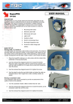
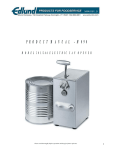
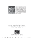
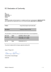
800-729-5051
SERVICE MANUAL- M126
MANUAL CAN OPENER- MODEL # 2
1
M126
M126
Model #2 Can Opener Assembly Procedure
800-729-5051
The Model #2 can opener will be assembled according to the following procedure.
I.
Model #2 Handle and Arbor Assembly (A508) (Fig. 1)
Insert arbor (A026) into slot at end of handle assembly (A509). Align holes and secure using a roll pin (P030).
II. Model #2 Knife holder Assembly (A518) (Fig. 1)
Place the knife (K005) on tang of knife holder (H020). Secure knife holder using screws (S072).
III. Model #2 Main Assembly
Place spring (S151) and washer (W037) into hole in top of slide bar (B009/B012). Insert spring compression
tool (A5191) into rear of gear slot and compress washer and spring until knife holder ears will slide over the
washer. Align the holes in slide bar and knife holder and insert rivet (R041) through both parts. Place head of
rivet on top of steel plate and upset other end of rivet using hammer.
Remove the spring compression tool and insert gear (G004) with stamped word "Edlund Up" toward top of side
bar. Place bushing (B121) into opening at top of slide bar and slide arbor of handle and arbor assembly (A508)
down through bushing, washer and spring and into gear. Screw arbor into gear while keeping gear from rotating
by inserting soft nail or screw into space on left side of gear between the gear and the edge of the gear slot.
Turn handle clockwise until arbor and gear are fully tightened. When gear and arbor are properly assembled
there should be very little space between the top of the bushing and the bottom of the handle.
Lubricate the arbor hole using non-sticking vegetable oil and inspect using final test instructions EC1066A.
IV. #2 Can Opener Maintenance
1. #2 Knife Replacement Procedure
The knife (K005) should be checked periodically to make sure that there are no nicks or grooves on the cutting
edge of the knife. The knife should be reversed or replaced to use the unused cutting edge or replaced using
new knife.
Raise the handle and remove the two screws (S072) that retain the knife to the knife holder and reverse the knife
or replace with a new knife and secure using the two screws.
2. #2 Gear Replacement Procedure
If gear will no longer turn a can or starts to remove metal from the can bead, the gear needs to be replaced. To
remove the gear, place a soft nail or screw on the right side of the gear between the gear and the edge of the gear
slot to keep gear from rotating. Turn handle counterclockwise until arbor is free from gear. Replace the gear
and assemble the gear according to the previous assembly procedure.
2
M126
M126
Care and Maintenance Procedures
800-729-5051
The Model #2 manual can opener, manufactured by the Edlund Company, must receive proper
care and maintenance in order to function properly and to prevent any unsafe conditions over the
life of the product or the life of any of its components. To ensure maximum life of the opener,
the following care and maintenance procedures should be followed:
I.
Cleaning Procedure
The can opener must be cleaned daily or after each extended use as follows:
A. Remove all the food and can opening residues from the drive gear, the drive gear
cavity, the knife and the area around the can stop using the stainless steel cleaning brush,
(Edlund Model #ST-93). Regular use of this tool will help prevent unwanted product
buildup and harmful bacteria growth.
B. Wash the knife, gear and any splash area on the opener using soap and water.
C. Thoroughly dry the knife, gear and can opener using a dry cloth or paper towel.
D. Coat the knife and gear with non-sticking vegetable oil to prevent rusting when the
can opener is not in use.
II.
Maintenance Procedure
Periodically perform maintenance as follows to ensure sanitary and safe food handling
requirements and to extend the life of your opener.
A. Check the shear blade or knife by running a fingernail over the cutting edge to make
sure a sharp groove does not develop. A groove can cause metal can slivers. If a groove
is found remove the two screws securing the knife to the knife holder and turn over to use
the unused cutting edge or replace the blade with a new blade or knife. Place the knife
support over the top of the knife and secure using the two knife holder screws. This
inspection should be done when the can opener is cleaned. Please note: The Edlund
knife is intentionally dull with rounded edges to prevent can slivers. However, the
friction of metal-to-metal contact between the knife and the can will eventually cause the
blade to sharpen itself. Check the knife regularly for sharp edges and grooves and
remember, “Never sharpen can opener blades.”
B. The drive gear should be inspected for wear monthly by first opening up a dent free
#10 can with the opener. Inspect the can bead to see if the lines left by (tooth marks) the
drive gear are narrow and evenly spaced, or if they are wide which indicates that the gear
is slipping and may be removing metal from the can bead. If the gear is removing metal
from the can bead, or “milling,” inspect the gear for wear.
3
M126
M126
800-729-5051
If the teeth of the drive gear are dull, replace the drive gear using the procedure listed in
Paragraph C below.
If the gear teeth appear to be sharp, inspect the arbor hole located below the gear by
turning the opener upside down and determining if the hole is elongated or worn. If the
hole is elongated, the opener is beyond repair and must be replaced.
C. Drive gear replacement is accomplished by first removing the knife and knife support
from the knife holder. Place the can opener in the can opener base and place a nail,
flathead screwdriver or other soft metal object to prevent rotation of the gear in the space
on the right side of the gear between the gear and the edge of the gear slot. Remove the
handle and arbor assembly from the gear by turning the handle counter-clockwise until
the handle is detached from the drive gear. Remove the worn drive gear and gear washer
from the gear slot and place the gear washer over the new gear with the word “up” toward
the top of the can opener. Replace the gear and gear washer in the gear slot and insert the
handle and arbor assembly back through the bushing and spring and into the threaded
hole of the gear. Place a nail or soft metal object to prevent gear rotation in the space on
the left side of the gear between the gear and the edge of the gear slot and rotate the
handle clockwise until the assembly is tightened completely. Replace the knife and knife
support and attach using the two knife holder screws.
D. To prevent premature wear of the arbor hole of the slide bar, place a small amount of
non-sticking vegetable oil in the arbor hole located under the drive gear weekly or after
each cleaning.
E. The can opener and base should be inspected weekly for any excessive wear or rust on
any surface. If rust or wear is found to be excessive, replace the can opener and/or the
base as required.
4
M126
Problem
I. Can opener will
not turn can.
M126
TROUBLE SHOOTING GUIDE
Cause
800-729-5051
Correction
1. Drive gear is worn.
1. Replace gear (G004).
2. Drive gear needs cleaning.
2. Clean drive gear (G004) using cleaning brush
(ST-93).
3. Replace can opener.
3. Arbor hole in slide bar or
arbor is worn allowing gear to
move out of contact with the
can bead.
1. Worn ears on knife holder. 1. Replace knife holder (H020).
II. Knife will not
lift far enough from
gear to pierce can
when handle is
lifted.
III. Metal slivers
found in food
product.
2. Worn bushing (B121).
3. Worn handle (H002).
2. Replace bushing.
3. Replace handle.
1. Nick or groove on cutting
edge of knife (K005).
1. Reverse knife or replace
2. Worn drive gear (G004).
2. Replace gear.
3. Sharp edge on slide bar can 3. Round sharp edges with file or replace can
opener.
stops.
1. Worn or loose bar holder on 1. Replace base.
IV. Can Opener
withdraws from can base.
during can opening
procedure.
2. Can opener used in base or 2. Replace base or repair hole in table to include
preparation table that doesn't two-degree angle to bar holder.
have two-degree angle on bar
holder.
Note: Edlund Company manufactures the most complete line of can opening equipment in the
world. Each model is designed for specific applications and/or volume requirements, and if used
and maintained properly, will last a long time. If your operation requires opening 200 cans per
day, a manual opener designed for 50 cans per day will wear out more quickly than necessary.
Please follow Edlund’s guideline for recommended applications found in our catalogue and price
list.
5
M126
M126
800-729-5051
6
M126
M126
`
Parts List
800-729-5051
PART #
U/M
DESCRIPTION
A026
A504
A505
A506
A508
A509
A518
A5191
B009
B012
B121
G004M
G004SP
H002
H020
K005M
K005SP
K011
L015
N059
P030
R041
S010
S011
S072
S151
S198
S503
W037
EA.
EA.
EA.
EA.
EA.
EA.
EA.
EA.
EA.
EA.
EA.
BOX
EA.
EA.
EA.
BOX
PKG.
EA.
EA.
PKG
EA.
EA.
PKG.
PKG.
EA.
EA.
EA.
PKG.
EA.
ARBOR, #2
ASSEMBLY, #2 CRS (MILD STEEL) BASE
ASSEMBLY, #2 STAINLESS STEEL BASE
ASSEMBLY, #2/#8 CLAMP, THUMB SCREW
ASSEMBLY, #2 HANDLE/ARBOR
ASSEMBLY, #2/#8 HANDLE & KNOB
ASSEMBLY, #2 KNIFEHOLDER
ASSEMBLY, #1/#2 SPRING RELEASE CLAMP
BAR, #2 SLIDE XL (CASTING ONLY)
BAR, #2 SLIDE (CASTING ONLY)
BUSHING, #2
GEAR, #2 24 PKG.
GEAR, #2 SINGLE PACK
HANDLE, #2 & #8
HOLDER, #2 KNIFE
KNIFE, #2/20 24 PKG.
KNIFE, #2/20 SINGLE PACK
KNOB, MANUAL CAN OPENER
#1/#2 WARNING LABEL FOR BASE
NUT, 10-32 SELF LOCKING (3 PKG. W/S503)
PIN, ROLL, 3/16 X 1-1/8 PLATED
RIVET, #2 KNIFEHOLDER
SCREW, 12 X 1 S/S FOR BASES, PKG. OF 3
SCREW, 12 X 1 PLATED FOR BASE, PKG. OF 3
SCREW 12-24 X 7/16 RHM
SPRING, #2
STUD, #1/#2 KNOB
SCREW, 10-32 X 1 S/S SLOTTED (3 PKG. W/N059)
WASHER, #2 SPRING
7
M126
M126
FINAL INSPECTION INSTRUCTION
DOC: EC1066 C
MODEL: NO. 2 MANUAL CAN OPENER
DATE
MODEL: NO. G2 MANUAL CAN OPENER EFFECTIVE: 01 Oct 2000
OWNER: QUALITY ASSURANCE MANAGER
Reference only
THIS HARD COPY MAY BE OBSOLETE
VERIFY THE ABOVE IS THE LATEST USING THE MASTER LIST OR CONTACT
THE DOCUMENT CONTROL COORDINATOR.
OBSOLETE DOCUMENTS MUST BE PROMPTLY REMOVED FROM USE
1.0 PURPOSE and SCOPE
To provide a uniform and consistent method for acceptance/rejection of finished product.
2.0 INSTRUCTION
2.1 FUNCTIONAL TEST
2.1.1
Select a No.10 can, lift the slide bar handle to the open position; the handle shall operate smoothly
and freely without binding.
2.1.2
Check the “gap” or “lift” between the knife and gear using gauge no. EFG-30, the “gap” shall be
between one hundred ten thousandths (.110) to one hundred seventy thousandths (.170).
2.1.3
With the opener in the closed position, the gap or space between the knife and gear shall not exceed
fifteen thousandths (.015). Check with .015 feeler stock.
2.1.4
Place the slide bar into the test base, the stops under the head must contact the top of the test base,
position the selected can, pierce the can and lower the handle to the closed position, open the can.
2.1.5 The knife shall puncture the can easily and cleanly, iron closely and sever the lid completely.
2.1.6 The gear shall not skip, mill, or chatter during opening, the gear must not “drag”, in any way, on the
top or bottom of the gear slot
2.1.7 The gear teeth shall not “chip or break” during opening.
2.1.8 Remove the opener from the can and inspect the “can bead” for any indication of “milling” or
“skipping”.
3.0 VISUAL INSPECTION
3.1 Check to ensure that all fasteners (S198-S072) are tight and free of looseness.
3.2
Inspect for damaged or chipped plating or ”yellowing” of the plating (“yellowing” is most prevalent in “humid
weather”).
3.3 Inspect for obvious casting defects (holes-cracks-or broken slide bars).
G-2 ONLY:
3.1 Check to ensure that all weld seams are smooth and free of holes or pits.
3.2 Inspect for scratches or other surface blemishes that would take away from the appearance of the opener.
3.3 Inspect for obvious casting defects (holes, cracks or porosity)
3.4 Ensure the knife holder can be easily removed for cleaning.
3.5 Ensure that the knife holder cannot be removed without lifting or “cocking” of the handle.
4.0 END OF DOCUMENT
Rev. B: Added requirement to inspect gap at closed position.
800-729-5051
8