1
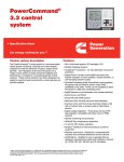
Operator Panel The operator panel provides the user with a complete package of easy to view and use information. It includes an enhanced graphical operator panel that allows the user to view up to 9 lines of information, as well as graphical displays of system data. Connections to the operator panel are sealed locking plug interfaces, for reliable, vibration-resistant interconnection to the generator set wiring harness. Control Switches and Functions via raise/lower switches on the operator panel. Functions that can be adjusted by the operator include: Time delay start (0-300 seconds) Time delay stop (0-600 seconds) Alternator voltage (plus or minus 5%) Alternator frequency (plus or minus 3 hertz). The operator panel can be configured to require an access code prior to adjusting these values. A second access code is used to protect the control from unauthorized service level adjustments. Voltage and frequency adjustments are disabled during operation in parallel with a system bus to prevent inadvertent misadjustment of the paralleling load sharing functions. PowerCommand Analog AC Metering Display Analog AC Metering Panel OFF/MANUAL/AUTO Mode Control Switch - The NOT IN AUTO lamp will flash when the control is in the MANUAL or OFF mode. In the AUTO mode, the generator set can be started using the exercise pushbutton, or with a start signal from a remote device, such as automatic transfer switches. MANUAL RUN/STOP Control Switch And Indicating LED - When the mode control switch is in the MANUAL position and the MANUAL RUN /STOP switch is pressed, the Generator set will start, bypassing all time delays for idle mode or time delay start. If the generator set is running in the MANUAL mode, pressing the RUN/STOP switch will cause the generator set to shut down. An LED (light emitting diode) lamp adjacent to the switch will light to indicate the generator set is in manual mode. EXERCISE Control Switch And Indicating LED When the mode control switch is in the AUTO mode the EXERCISE control switch is used to complete a pre-programmed exercise sequence. All exercise functions are disabled when an emergency start command is received by the control. An LED lamp adjacent to the switch will light to indicate the generator set is in exercise mode. PANEL LAMP/LAMP TEST Control Switch EMERGENCY STOP Control Switch Operator Adjustments - The control includes provisions for many set up and adjustment functions © 2002 Cummins Power Generation The PowerCommand control is equipped with an analog AC metering panel that simultaneously displays 3-phase line to line AC volts and current, kW, power factor, and frequency. The meter panel is composed of a series of LED’s configured in bar graphs for each function. The LED’s are color coded, with green indicating normal range values, amber for warning levels, and red for shutdown conditions. Scales for each function are in % of nominal rated values. Resolution is 1% for values close to nominal, and increases at increasing values from nominal. Specifications Subject to Change S1385d 1/2002