Download Broadcasting House
Transcript
Speed Post
Prasar Bharati
(Broadcasting Corporation of India)
Broadcasting House: All India Radio
New Delhi
No. DEL 1 (2)/BH/Console /2012-13-E
20.02.2013
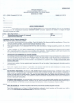
Corrigendum
Reference
dt.13.02.2013,
regarding
specification
attached
to this office Limited
the purchase
may be treated
herewith.
Tender
Enquiry
letter
of even no.
of Digital Recording Console, supplied
as cancelled
and a new fresh Specification
is
It is also mentioned that Bid security money may be read
as Rs.40,000/- instead of Rs.20,000/-.
The other terms & conditions will be same.
To
rvi/s ---------------
\\
9- \">
~~CJ-O()
(Jitendra
.
Sarswat)
AE
for DDG (E)
~IR
Website.
Prasar Bharati
(Broadcasting Corporation of India)
Broadcasting House: All India Radio,
New Delhi- 110001
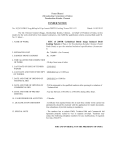
TECHNICALSPECIFICATIONFOR DIGITAL RECODINGCONSOLE:
1.
GENERAL
1.1
1.4
This specification is for Digital Audio Recording Console for use in Production
studios of All India Radio. The consoles shall be fully digital modular plug-in
design and based on the field proven modern technology. It should be rugged
in construction and suitable for reliable operation. 24 hrs. a day and 365 days
in a year.
Only professional and branded products manufactured by reputed companies
in sound broadcasting equipment field shall be offered.
The tenderer must submit the following documents along with the tender:
A point-to-point
compliance statement as per Annexure-I highlighting
deviations, if any, on all the clauses of specification from the manufacturer of
the offered equipment duly signed in original. Actual performance figures
should be quoted under remarks column. If compliance statement is in
format other that Annexure, the tender will be rejected out rightly.
Detailed printed literature of the equipment giving complete electrical and
mechanical data including detailed dimensions and mounting requirements.
The quote should either be from the original manufacturer or from their
authorized representative/ dealer. In case,' the quote is from the authorized
representative / dealer, a certificate in original from.the original manufacturer
that the tenderer is authorized representative / dealer for India should be
enclosed with the tender. In case, the quote is from both i.e. Authorized
representative/
dealer and also from original manufacturer, the quotation
from original manufacture will be considered for technical evaluation.
The tenderer may be required to demonstrate the functioning of the tendered
unit during technical evaluation verification of electrical performance
parameters as may be required during technical evaluation, in New Delhi.
Non-compliance of equipment demonstration, if asked for by the indenter,
shall disqualify the tender.
Incomplete offers will be rejected out rightly.
2.
SCOPEOF THE TENDER
1.2
a)
b)
c)
1.3
The specification is for supply of digital recording console (Including equipment
rack for mounting of electronics part of the console. If such a design console is
offered) along with all accessories, mating connectors and cables, etc. required
to be fully functional.
------------------------
----
I
3\
TECHNICAL SPECIFICATIN
3.1
General Features:
The console should be simple in operation.
The Console should be compact ergonomically designed professional product
and suitable for reliable operation on 24x7x365 basis working. It should be
housed in rust-proof
pre-painted metal cabinet. It may either be single
composite unit or the main electronics portion may be in separate 19 inch rack
mountable unit .:
3.1.1
3.1.2
3.1.3
3.1.4
The console should be suitable for tabletop mounting.
The layout of modules / parts/ components in the console should be
professional to permit easy access to the wiring, inspection, repairs/ servicing.
3.1.5 All the inputs and outputs should be available in 3-pin XLR or '0' type
connector for digital and on balanced 3-pin XLR for analog audio. The mating
pins of '0' connectors should be gold plated.
3.1.6 All switches/ buttons/ knobs operable by operator should be sturdy and
designed for reliable operation for long hours. Inputs/ outputs and connectors
shall not be on the working/ operating area of the console surface.
3.1.7 The controls for output bus assignment, channel on/off, monitoring level
control, talkback and signaling etc. should be appropriately
located on the
control surface of the console.
3.1.8 Provision for ganging the mono inputs for stereo operation should also be
available.
3.1.9 All selection points on the console surface shall be provided with clear
illuminated status indication, if required in different colours for easy under
standing.
3.1.10 Status indication in different colours, should be provided for signaling, talkJ
back from other consoles, on air, channel selection, PFL indication, stereo/
I
Mono an~ other operations.
3.1.11 Console should have facility
automation systems.
3.2
3.2.1
3.2.2
3.2.3
3.2.4
3.2.5
3.2.6
i
I.'
to work with
computer
based studio/
news
!
r
Input Fader channel Modules Features.
All the input fader channel modules should have following
minimum
provisions:Selection for feeding/ assigning any of the input to any of the output program
bus.
The control fader of each input/ output module should fade in from infinity to
zero to provide nominal output with minimum 10db reserve gain.
Console should have facility for Pre-Fade Listening (PFL), with suitable indicator
during PFL.
All the internal Audio Signal Processing in the consoled should be fully digital
signal processor based.
Various Control Circuits in the console should be digital and entire switching
shall be through solid-state digital switches.
A to 0 and 0 to A converters shall have minimum 24 bit resolution.
2
r
.
.
J
3.•2.7
3.2.8
3.3
3.3.1
3.3.1.1
3.3.1.2
3.3.1.~
3.3.1.4
3.3.1.5
3.3.1.6
3.3.1.7
3.3.1.8
3.3.2
There should be in-built world clock for synchronization of external digital
devices and provision should also exist to synchronize the console from an
external world clock or AES/EBU source.
All digital inputs and outputs will be in AES/EBU format and confirm to AES31992 signal format.
Input Configuration:
The consoles shall have minimum 12 faders. In case the. frame size is not
exactly matching the requirement of 12 input faders, higher frame size may be
offered.
The minimum
requirement
of input sources, faders and its
configuration are as detailed below:
1.
No. of Faders
12
2.
Provision to connect input sources:
(i)
Microphones
a)
Mono
8
b)
Stereo
Refer to item no. 3.3.13
(i i)
Line
Analogue mono line
a)
8 (with further provision to
configure as 4 stereo)
b)
Digital
8
3.
It should be possible to feed 4 Digital Stereo line inputs along with 8
mono mike inputs, with a facility to replace each mike input with a
mono line input.
Mono Mike Inputs
All mike channels should have the following provisions.
Input Level range adjustable -60 dBu to -35 dBu (Ref. 0 dBU = 0.775V rrns) with
sensitivity control.
Input impedance ~1 K ohms balanced.
\
Provision to gang two mike channels for feedrng ster~o (mike) input.
Phase reversal switch.
Built in switch-able Phantom supply of 48 volts.
Provision for muting of various monitoring speakers as detailed in section 3.12
Pan potentiometer.
Selectable inbuilt parametric equalizer with high Q capable of providing a least
±12dB equalization independent in each of three bands, i.e. at low, mid and
high audio frequencies.
Mono line inputs (Analogue)
All mono analogue channels shall have the following features and parameters .
Nominal level
+ 4 dBu with headroom of at least 15 dB
Maximum input level
+ 24dBu
Input impedance
~ 10K ohms balanced.
Balance control in each channel
./
3.3.2.1
3.3.2.2
3.3.2.3
3.3.2.4
Digital inputs
All Digital input channels shall have the following features/ parameters:
3.3.3.1 Level reference:
0 dB digital = + 24 dBu analogue
3.3.3
3.3.3.2 Signal format
3.3.3.3 Level:
input level
3.3.3.4 Internal sampling rates:
3.3.3.5 Convertor
(+ 4 dBu = - 20 dB FSD)
AES-3 of 1992
Digital input level should match the analogue
(as mentioned in para 3.3.2)
32kHz, 44.1 kHz and 48 kHz
AID 24-bit, SRCon all digital input
In build sampling rate converter on each digital
input channel to accept different Sampling rates.
3.4
Output Configuration:
The console should provide at least 4 independent stereo programme outputs,
each in analogue as well as in digital format.
3.4.1 Analogue Output
a)
Nominal output level .'
+4dBu, adjustable
+ 24 dBu
b)
Max. output level
::;60 ohms balanced
c)
Output (Source) impedance
600 ohm
d)
Output load impedance
3.4.2 Digital output
o dB digital = + 24 dBu analogue
a)
Level reference
Digital output level should match
b)
Output level
the analogue output level as
mentioned in para 3.4.1
110 ohms
c)
Output impedance
24 bit
d)
Conversion
3.5
3.6
Frequency Response over the entire frequency
at nominal input and nominal output levels.
a)
Mike inputs to program outputs
b)
Analogue I digital line inputs to
program outputs
Total Harmonic Distortion + Noise
a)
Mike pre input to analog output
b)
Analog input to analog output
c)
Digital input to digital output
d)
Digital input to analogue output
range of 20 Hz to 20 kHz and
within ± 0.5 dB
within ±0.3 dB
<0.01%, -35 dBu analog
input + 24 dBu analog
output, Filter BW 20 kHz
< 0.01%, + 24 dBu input,
+ 24 dBu output, Filter BW 20 kHz
< 0.01%, 20 Hz to 20 kHz, Filter BW
2(}-kHz + OdB, input,
+ OdB,
Output, filer BW 22 KHz
< 0.01%, 20 Hz to 20 kHz, Filter BW
20 kHz -ldB input, + 23 dB output,
Filter BW 22KHz
4
Equivalent
a)
b)
3.8
Stereo
Input Noise Level and Signal to Noise ratio.
Equivalent input noise for mike channel shall be better than - 125 dBu
(for Microphone channels, with nominal input level of -60 dBu and
nominal output of +4dBu (rest of the input faders in off position) and
measurement band limited to 20 Hz to 20KHz).
Signal to Noise Ratio for Line channel ~80dB (with nominal input level
of + 4 dBu in line channel and + 4dBu output level and rest of the input
faders in off position with measurement band limited to 20 Hz -20 kHz)
Separation:
Channel separation (Between L&R of same channel), better than 60dB, with
maximum input and output at frequency band of 20 Hz to 20 kHz.
3.9
Inter channel cross Talk:
Better than 90 dB, with maximum input and output
limited to 20 Hz - 20kHz,
and measurement
band
Monitoring
Facilities:
3.10
3.10.1 Announcer/ Recording booth monitor:
Monitoring signal of OdBu nominal level should be available for monitoring on
external speakers for anyone of the programme outputs selected. Headphone
monitoring facilities should also be available. Both the monitoring facilities
shall have build-in level controls of 10dB. It should be possible to select any of
the two external stereo sources on the monitor.
3.10.2 Studio Monitor
Similar monitoring facilities, as under para 3.10.1, should be provided
artists in studio for anyone of the programme outputs selected.
for
3.10.3
PFL Monitor
Facility to monitor all input channels in a built-in PFL speaker as well as on
headphone should be provided.
PFL speaker as well as headphone should
have in-built level control of 10dB.
3.11
Talk-Back
Talkback facility with another console, installed in control room, other studios
and dubbing room shall be available. The talk back mike should be preferably
in-built.
3.12
Mute Controls
PFL, Talkback and Announcer monitor speakers in Announcer Booth of the
studio shall get muted when anv mike channel is faded in. Similarly, studio,
monitor for artists shall be muted when any artist - mike is faded in.
5
3.13
Signaling & Warning Lights
a)
Provision for a 'red-light' (On-Air) indication on the console surface (by
receiving 0 logic controlled from the console in control room) shall be
provided.
b)
Provision for generating at least two warning light signals (0 logic)
controlled from each mike fader.
c)
Provision should also exist for generating 'green light for sending ready
signal in control room by extending '0' logic.
3.14
Metering
Two numbers of LCD/LED indicators to provide the VU as well as PPM
(selectable) should be available to monitor the level on any of the output
buses.
3.15
Power Supply
3.15.1 The console shall work on 230V ±10%, 50Hz ±6% single-phase AC supply.
3.15.2 The power supply unit of the console should be protected against overload,
short circuit and over-voltage.
3.15.3 Power supply unit / module should either be external (19 inch rack mountable)
or in case of internal, temperature
of console front surface should be
comfortable when power is ON.
3.16
Climatic Conditions.
The console will generally be installed in air-conditioned
environment.
However, the console should perform satisfactorily in the dry temperature
range of 5°C to 40°C and humid conditions prevailing in tropical climate. A test
certificate in this regard should be produced \roQ'l an approved Test House.
3.17
Accessories.
\
Each console shall be supplied with following accessories/ Items and their cost
shall be included in quotation.
3.17.1 19 Inch mounting rack should be provided if the electronics of the console is
separate from the table top of the console.
3.17.2 A complete set of mating connector (with gold plated contacts) and power
chord etc.
3.17.3 A set of operation manual and service manual.
3.17.4 Any other item, including interconnecting cables and related configuration
software (Pre-loaded and on Media CD/DVD) for console etc. required for
../making the console fully, operational.
4.
GUARANTEE/
4.1
The equipment shall be guaranteed for trouble free operation for a minimum
period of one year from the date of supply. Replacement/ servicing shall be
effected free of cost for hardware and software during the guarantee period.
WARRANTY
6
·. 1
:!
!
r
4.2
4.3
4.4
4.5
5.
The contractor/ seller hereby guarantee that the said goods/ stores/ articles
would continue to conform to the description and quality aforesaid for a
period of 36 months from the date of installation and commissioning at the
consignee's site, if during the aforesaid period of 36 months the said goods/
stores/ articles be discovered not to conform to the description and quality
aforesaid, the purchaser shall be entitled to call upon the contractor/ seller to
rectify goods/ stores/ articles or such portion thereof as is found to be
defective by the purchaser with a reasonable period or such specified period as
may be allowed by the purchaser in his discretion on application made thereof
by the contractor / seller and in such an event the above mentioned warranty
period shall apply to the goods/ stores/ articles rectified from the date of
rectification warranty period shall apply to the contractor / seller pay to the
purchaser such compensation as may arise by reasons of the breachof the
warranty herein contained.
Guarantee that firm will supply spare parts, if and when required on the
agreed price. The agreed basis could be including but without any limitation on
agreed discount on the published catalogue or an agreed percentage of profit
on the landed cost.
Warranty to the effect that before going out of production for the spare parts
they will give adequate advance notice to the purchaser of the equipment so
that latter may undertake the balance of the life time requirements.
Warranty to the effect that firm will make available the blue prints of the
drawings of the spares, if and when required in connection with the main
equipment.
SPARES
The essential recommended spares should be quoted separately. The list
should include name and part no. with quantitv and its unit cost. The tenderer
shall ensure availability of spares in India for the quoted equipment for a
period of at least 5 year from the date of supply of the equipment. The cost for
software upgrade, if any, shall also be quoted as an option.
6.
ELECTROMAGNETIC
COMPATIBILITY
The console shall conform to the electromagnetic standards that are listed in
the guidelines 89/ 336/ EC & FCC Part 15. The certificate from independent
test laboratory regarding compliance to the aforesaid standard should be
attached with the technical bid.
7.
TRAINING
The tenderer shall be required to train at least 2 AIR persons on operation,
maintenance and repair of the equipment.
***
7


