1
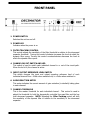
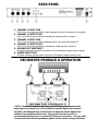
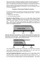
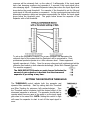
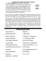
INTRODUCTION
The Decimator ProRackG guitar noise reduction system defines a new standard for excellence in real time
noise reduction performance. The Decimator ProRackG was designed to provide the maximum possible
performance in a rack mount dual channel noise reduction system designed specifically for extremely
high gain guitar amplifiers. The Decimator ProRackG offers the only system designed with two channels
of single ended noise reduction configured for the guitar application allowing one channel to drive the
front end of the guitar amplifier and a second channel that tracks in guitar signal directly with the signal
processing chain inserted in the effects loop of the amplifier. Now you can quiet down even the most
insane amounts of noise with any amplifier system incorporating a series effects loop. The Decimator
ProRackG has dual processing channels incorporating both low-level downward expansion and
dynamically controlled low-pass filtering in a very easy to use single rack space unit. The Decimator
ProRackG is based on ISP Technologies patent pending “Time Vector Processing” which provides the
most adaptively dynamic release response characteristics of any real time noise reduction system. The
patent pending Time Vector Processing dynamic response circuit is used to control the release time
constant of both the downward expander and dynamic filter. Not only does the Decimator ProRackG
deliver the most stunning noise reduction is also solves the problem of needing to adjust the Threshold
setting every time you change gain or switch channels. By using the input guitar signal to drive both
channels level detection circuitry the ProRackG needs no other adjustments once the thresholds are set
based on the guitar input.
This will give you the correct threshold with clean, crunch and even
monstrous amounts of gain and if you use pedals you can insert them in the loop between the output of
the Decimator Channel 1 and the input of the guitar amplifier. The Decimator ProRackG is based on ISP
Technologies patent pending “Time Vector Processing” which provides the most adaptively dynamic
release response characteristics of any real time noise reduction system. The patent pending Time
Vector Processing dynamic response circuit is used to control the release time constant of both the
downward expander and dynamic filter.
Please read this manual carefully for a through explanation of the Decimator ProRackG and its functions.
PRECAUTIONS
NOTE: IT IS VERY IMPORTANT THAT YOU READ THIS SECTION TO PROVIDE
YEARS OF TROUBLE FREE USE. THIS UNIT REQUIRES CAREFUL HANDELING.
All warnings on this equipment and in the operation instructions should be adhered to and
all operating instructions should be followed.
Do not use this equipment near water. Care should be taken so that objects do not fall onto
and liquids are not spilled into the unit through any openings.
The power cord should be unplugged from the outlet when the unit is left unused for a long
period of time.
DO NOT ATTEMPT TO SERVICE THIS EQUIPMENT. THIS EQUIPMENT SHOULD BE
SERVICED BY QUALIFIED SERVICE PERSONNELL ONLY. DO NOT MAKE ANY INTERNAL
ADJUSTMENTS OR ADDITIONS TO THIS EQUIPMENT AT ANY TIME. DO NOT TAMPER
WITH INTERNAL ELECTRONIC COMPONENTS AT ANY TIME. FAILURE TO FOLLOW THESE
INSTRUCTIONS WILL VOID THE WARRANTY OF THIS EQUIPMENT, AND MAY CAUSE A
SHOCK HAZZARD.
POWER REQUIREMENTS
This unit accepts power from the 9V AC power adaptor supplied with the unit. This 9V RMS
AC voltage is internally processed by a voltage doubler, which generates a bi-polar + and –
15V power supply to maintain the headroom and sound quality of professional, studio
quality equipment. Using an external power source minimizes excessive noise and hum
problems often associated with internal transformers, providing optimal performance for the
user.
FRONT PANEL
1. POWER SWITCH
Switches the unit on and off.
2. POWER LED
Indicates when the power is on.
3. FILTER TRACKING CONTROL
This control adjusts the sensitivity of the filter threshold in relation to the downward
expander threshold. Turning this control clockwise increases the level at which the
dynamic filter opens. Turning this control counterclockwise decreases the level at
which the dynamic filter opens.
4. CHANNEL IN/OUT SWITCH AND LED
This switch is used to switch each individual channel in or out of the circuit path.
When the led is lit, the channel is active.
5. INPUT/OUTPUT REFERENCE LEVEL SWITCH
This switch changes the input and output operating reference level of each
individual channel from –10dbu when switched out, to +4dbu when switched in.
6. GAIN REDUCTION METER
This meter indicates the current amount of gain reduction (in decibels) taking place
in each channel.
7. CHANNEL THRESHOLD
This is the master threshold for each individual channel. This control is used to
adjust the threshold for both the dynamically controlled low pass filter and the low
level downward expander. NOTE: Adjusting the Filter Tracking control will shift
the sensitivity of the dynamic filter in relation to the sensitivity of the downward
expander.
REAR PANEL
1. CHANNEL 1 INPUT JACK
This ¼ inch mono jack provides the high impedance input for connection to your guitar.
2. CHANNEL 1 OUTPUT JACK
This ¼ inch mono jack provides the unbalanced output signal for channel 1.
3. CHANNEL 2 INPUT JACK
This ¼ inch mono jack provides a balanced input for the audio path channel 2.
4. CHANNEL 2 OUTPUT JACK
This ¼ inch mono jack provides the unbalanced output signal for channel 2.
5. GROUND LIFT SWITCHES*
All switches eliminate the ground connection for the illustrated channel input or output.
6. POWER INPUT JACK
This jack connector accepts power from the 9V AC adaptor supplied with the unit.
DECIMATOR PRORACK G OPERATION
*NOTE: Ground Lift switches allow the user to lift the ground between the
output signal of channel one of the ProRack G and the input of the selected
amplifier, and between each of channel two’s input and output signals that
connect to an amplifiers effects loop. If a ground loop hum occurs it is
recommended to disconnect or ground lift all but one connection. You may want
to experiment with the best grounding option for the lowest noise performance.
When properly used, the Decimator ProRack G should be completely transparent, it
should have no effect on the audio signal other than to remove the background
noise. To maximize the performance of the Decimator, it is necessary to understand
both the operation of the controls and the principles of how the internal circuit
operates. After this understanding, it will be easier to set up the Decimator ProRack
G to suit any application.
Principles of the Decimator ProRack G operation:
The Decimator achieves noise reduction by employing two individual noise reduction
processes, which work cohesively together to attain superior results. These two
processes are:
1. Dynamic Low Pass Filtering
2. Low Level Downward Expansion
Dynamic Low Pass Filtering is done by use of a high quality voltage controlled
sliding filter. A frequency sensitive audio level detection circuit incorporating ISP
Technologies patent pending Time Vector Processing circuit controls the dynamic
filter.
When the audio input signal contains high frequency information the
dynamic filter increases in bandwidth to allow the audio signal to pass unaltered and
shown in the simplified graph below.
When the high frequency information in the input signal decreases the dynamic filter
bandwidth will track the decrease in high frequency and eliminate high frequency noise
that remains in the input signal. The simplified graph below shows the dynamic filter
response when there is no high frequency audio above 1KHz.
The release time of the dynamic filter is controlled by the Time Vector Processing
circuit, which determines the release characteristics of the input signal and
automatically varies the release response of the dynamic filter.
Low Level Downward Expansion is performed by use of a high quality voltage
controlled amplifier controlled by an RMS based audio level detection circuit. A
second Time Vector Processing circuit that varies the release response over a 1000
to 1 ratio controls the release response of the Downward Expander. The release
response will be extremely fast, on the order of 2 milliseconds, if the input signal
has a fast decaying envelope and upwards of 2 seconds if the input signal has a
slow decaying signal. Downward Expansion takes place when the input signal level
drops below the preset threshold. For example: if the threshold is set for 0db and
input signal of 0db with produce no expansion. As the input signal drops below 0db
downward expansion starts and increases exponentially the farther the input signal
drops below the threshold point. The graph below shows the response of the
Expander with a 0db threshold.
To set up the Decimator ProRack G for proper operation first determine the
reference level of the system that the Decimator will be connected to. Most
professional products operate at a +4dbu reference level. Music equipment
typically operates at –10dbu. Once the proper reference level is determined set the
reference level switch on both channels accordingly. (Note: Both Channel One and
Two must be engaged.)
The GAIN REDUCTION meter on each channel indicates the
amount of gain reduction in decibels that the downward
expander is providing at any time.
SETTING THE DECIMATOR THRESHOLD
The THRESHOLD control adjusts both the expander and
dynamic filter sensitivity. Start by setting both the Threshold
and Filter Tracking for minimum, full counterclockwise. Turn
the Threshold control clockwise until the desired effect of the
downward expander is achieved. The expander should start to
operate when there are gaps in the audio or as the input signal
gets close to the noise floor. NOTE: Setting this control to high
will cause the expander to start to cut off the input signal to
soon.
SETTING THE FILTER TRACKING CONTROL
The FILTER TRACKING control adjusts the relationship
between the sensitivity of the Dynamic Filter and the Expander.
Once the THRESHOLD control is set for proper operation of the
downward expander increase the FILTER TRACKING control
until the desired dynamic filter operation is achieved. Setting
this control to high will cause the filter to not fully open when
high frequency signals are present. Setting this control to low
will not provide any high frequency noise reduction. The Filter
Tracking adjusts the tracking for both channels.
Once the filter is set correctly the dynamic filter will provide high frequency noise
reduction at all input signal levels. For example; if a high level input signal is present at
the input that contains low and mid frequency information but little or no high
frequency information the filter bandwidth will close to a point just above the highest
input frequency. The instant the input signal contains a high frequency audio signal
the bandwidth of the filter will open so as to allow the highs to pass unaltered. Since
the ear cannot detect a low level signal in the presence of a higher level signal in the
same frequency band the input signal will mask the audibility of the high frequency
noise. As the high frequency information in the input signal decays the filter will close
to reduce the audible level of the background noise. When set properly, the Decimator
should virtually eliminate all background noise and should operate with total
transparency.
SPECIFICATIONS
Input Impedance
470K ohms
Maximum Input Level
+15dbu typical
Input / Output Jack
¼ Balanced / ¼ Unbalanced
Frequency Response
+.1,-.5db, 20Hz to 30KHz
Total Harmonic Distortion
Less than .02% Typical
Dynamic Range
115db, Peak to A weighted floor
Effective Noise Reduction
Greater than 120db with both channels
Dynamic Filter Attenuation Slope
6db per Octave
Noise Floor
-110 A weighted typical –10 ref
Power Requirements
9V AC 1000ma
Dimensions
19” x 6” x 1¾”
NOTE: ODBU = .775V RMS
WARRANTY AND SERVICE
The unit, parts and workmanship are fully guaranteed to be free of defects under
normal use and service for a period of 2 years from the date of purchase.
Any damage resulting from the misuse or the failure to follow the precautions
and instructions will void the warranty.
In the event that the unit needs to be repaired, please return the unit to ISP
Technologies directly. Simply repack the unit, send a copy of the original receipt, a
note stating the problem, and send it to:
ISP Technologies, LLC
5479 Perry Drive Unit B
Waterford, MI 48329
Attn: Repair Dept.
All shipping charges must be fully prepaid.
ISP will not be responsible for any damages incurred in shipping of any unit. Any
claim will need to be settled with the shipping company.
NOTE: This Product may be covered under one or more of the following patents or
patents pending: 7,035,413; 6,944,305; 6,931,134; 6,831,514; 6,091,013
The warranty will be voided if the serial number has been tampered with in any
way.
The warranty card must also be filled out and returned in order to activate the
warranty.
Should you have any questions for the repair department prior to returning the
product please call 1-(248)-673-7790
ISP TECHNOLOGIES, LLC
5479 PERRY DRIVE SUITE B
WATERFORD, MI. 48329
248-673-7790
FAX: 248-673-7696
WWW.ISPTECHNOLOGIES.COM