1
®
Getting Started with
System Two Cascade PLUS
Getting Started with
System Two Cascade Plus
An Introductory Guide to
System Two Cascade Plus
September 2002
Copyright Ó 2002 Audio Precision, Inc.
All rights reserved.
Part Number 8211.0142 Revision 0
No part of this manual may be reproduced or transmitted in any
form or by any means, electronic or mechanical, including
photocopying, recording, or by any information storage and
retrieval system, without permission in writing from the
publisher.
Audio Precision®, System One®, System Two™, System Two
Cascade™, System Two Cascade Plus™, System One +
DSP™, System Two + DSP™, Dual Domain®, FASTTEST®,
and APWIN™ are trademarks of Audio Precision, Inc.
Windows is a trademark of Microsoft Corporation.
Published by:
Audio Precision
5750 SW Arctic Drive
Beaverton, Oregon 97005
Tel: 503-627-0832 Fax: 503-641-2209
U.S. Toll-Free: 1-800-231-7350
e-mail: [email protected]
Web: audioprecision.com
This mark signifies that the product conforms to all
applicable requirements of the European
Community. A Declaration of Conformance is
included with the user information that describes the
specifications used to demonstrate conformity.
Printed in the United States of America
II0909094355
Contents
Safety Information . . . . . . . . . . . . . . . . . . . . . . . . . . v
Safety Symbols . . . . . . . . . . . . . . . . . . . . . . . . . . . . vi
Disclaimer . . . . . . . . . . . . . . . . . . . . . . . . . . . . . . . vi
Chapter 1
Introduction. . . . . . . . . . . . . . . . . . . . . . . .
Scope of This Manual . . . . . . . . . . . . . . . . . .
Related Documentation. . . . . . . . . . . . . . . . .
Overview . . . . . . . . . . . . . . . . . . . . . . . . .
General System . . . . . . . . . . . . . . . . . . . .
System Two Cascade Plus . . . . . . . . . . . . . . .
GPIB (“G”) Option . . . . . . . . . . . . . . . . . . . .
Additional Options for System Two Cascade Plus .
Switchers . . . . . . . . . . . . . . . . . . . . . . . .
DCX-127 Multi-Function Module . . . . . . . . . . .
PSIA-2722 Programmable Serial Interface Adapter.
.
.
.
.
.
.
.
.
.
.
.
.
.
.
.
.
.
.
.
.
.
.
.
.
.
.
.
.
.
.
.
.
.
.
.
.
.
.
.
.
.
.
.
.
.
.
.
.
.
.
.
.
.
.
.
.
.
.
.
.
.
.
.
.
.
.
.
.
.
.
.
.
.
.
.
.
.
1
1
1
2
2
2
3
3
5
6
7
Chapter 2
Specifications . . . . . . . . . . . . . . . . . . . . . . . . . . . . . . 9
Analog Signal Outputs. . . . . . . . . . . . . . . . . . . . . . . . . 9
D/A Generated Analog Signals . . . . . . . . . . . . . . . . . . . . 13
Analog Analyzer . . . . . . . . . . . . . . . . . . . . . . . . . . . 16
Option Filters . . . . . . . . . . . . . . . . . . . . . . . . . . . . . 21
Option S-AES17 . . . . . . . . . . . . . . . . . . . . . . . . . . . . 26
DSP Analysis of Analog Signals . . . . . . . . . . . . . . . . . . . 27
Digital Signal Generator . . . . . . . . . . . . . . . . . . . . . . . 32
AES/EBU Interface Generation . . . . . . . . . . . . . . . . . . . 36
Getting Started with Cascade Plus
i
Digital Analyzer . . . . . . . . . . . . . . . . . .
Graphs of Typical Digital Domain Performance
Auxiliary Signals . . . . . . . . . . . . . . . . .
Audio Monitor . . . . . . . . . . . . . . . . . .
General/Environmental . . . . . . . . . . . . .
Cables and Adapters . . . . . . . . . . . . . . .
Analog Audio Cables . . . . . . . . . . . . . .
Digital Audio Cables . . . . . . . . . . . . . . .
Cable Adapters . . . . . . . . . . . . . . . . .
Digital Control (APIB) Cables . . . . . . . . . .
Chapter 3
Hardware Installation . . . . . . . . . . . . .
Rack Mounting . . . . . . . . . . . . . . . . .
Fixed Rack-Mounting Brackets . . . . . . .
Sliding Rack-Mounting Brackets . . . . . .
Checking or Changing Power Line Voltage
Fuse Information. . . . . . . . . . . . . . .
Changing Fusing Arrangement . . . . . . .
Proper Environment. . . . . . . . . . . . .
Connecting Cascade Plus to Your PC . . . . .
Installing the ISA-WIN APIB Card . . . . . .
ISA Card Address Jumper Settings . . . .
Installing a PCI-WIN APIB Card . . . . . . . .
Using the PCM-WIN PCMCIA Interface Card.
Connecting the APIB Interface . . . . . . . .
.
.
.
.
.
.
.
.
.
.
.
.
.
.
.
.
.
.
.
.
.
.
.
.
.
.
.
.
.
.
.
.
.
.
.
.
.
.
.
.
.
.
.
.
.
.
.
.
.
.
.
.
.
.
.
.
.
.
.
.
.
.
.
.
.
.
.
.
.
.
.
.
.
.
.
.
.
.
.
.
.
.
.
.
.
.
.
.
.
.
.
.
.
.
.
.
.
.
.
.
.
.
.
.
.
.
.
.
.
.
.
.
.
.
38
43
44
45
46
47
47
48
49
49
.
.
.
.
.
.
.
.
.
.
.
.
.
.
.
.
.
.
.
.
.
.
.
.
.
.
.
.
.
.
.
.
.
.
.
.
.
.
.
.
.
.
.
.
.
.
.
.
.
.
.
.
.
.
.
.
.
.
.
.
.
.
.
.
.
.
.
.
.
.
.
.
.
.
.
.
.
.
.
.
.
.
.
.
.
.
.
.
.
.
.
.
.
.
.
.
.
.
.
.
.
.
.
.
.
.
.
.
.
.
.
.
.
.
.
.
.
.
.
.
.
.
.
.
.
.
.
.
.
.
.
.
.
.
.
.
.
.
.
.
51
51
51
52
53
54
55
55
56
56
57
57
58
59
Chapter 4
Software Installation . . . . . . . . . . . . . . . . . . . . . . . . 61
Using the PCM-WIN card with Windows 95 or NT . . . . . . . . . 66
Chapter 5
Getting Started with APWIN . .
Running Your First Tests . . . . .
Running a Test Manually. . . .
Running a Saved Test . . . . .
Using the Quick Launch Menu.
Moving On. . . . . . . . . . . . .
APWIN Help . . . . . . . . . . . .
Technical Support . . . . . . . .
Chapter 6
Supplemental Information . . .
User Preferences . . . . . . . . .
Automating APWIN Startup . . .
Windows 95, 98, 2000, and NT.
ii
.
.
.
.
.
.
.
.
.
.
.
.
.
.
.
.
.
.
.
.
.
.
.
.
.
.
.
.
.
.
.
.
.
.
.
.
.
.
.
.
.
.
.
.
.
.
.
.
.
.
.
.
.
.
.
.
.
.
.
.
.
.
.
.
.
.
.
.
.
.
.
.
.
.
.
.
.
.
.
.
.
.
.
.
.
.
.
.
.
.
.
.
.
.
.
.
.
.
.
.
.
.
.
.
.
.
.
.
.
.
.
.
.
.
.
.
.
.
.
.
.
.
.
.
.
.
.
.
.
.
.
.
.
.
.
.
.
.
.
.
.
.
.
.
67
68
70
72
74
76
76
77
.
.
.
.
.
.
.
.
.
.
.
.
.
.
.
.
.
.
.
.
.
.
.
.
.
.
.
.
.
.
.
.
.
.
.
.
.
.
.
.
.
.
.
.
.
.
.
.
.
.
.
.
.
.
.
.
.
.
.
.
.
.
.
.
.
.
.
.
.
.
.
.
79
79
82
82
Getting Started with Cascade Plus
Command Line Options and Switches . . . . . . . . . . . . . . 83
Using Printers with APWIN. . . . . . . . . . . . . . . . . . . . . . 84
Publishing Graphs . . . . . . . . . . . . . . . . . . . . . . . . . . 84
Getting Started with Cascade Plus
iii
iv
Getting Started with Cascade Plus
Safety Information
Do NOT service or repair this product unless properly qualified.
Servicing should be performed only by a qualified technician or an
authorized Audio Precision distributor.
Do NOT defeat the safety ground connection. This product is designed
to operate only from a 50/60 Hz AC power source (250 V rms maximum)
with an approved three-conductor power cord and safety grounding. Loss
of the protective grounding connection can result in electrical shock hazard
from the accessible conductive surfaces of this product.
For continued fire hazard protection, fuses should be replaced ONLY
with the exact value and type indicated on the rear panel of the instrument
and discussed on page 54 of this manual. The AC voltage selector also
must be set to the same voltage as the nominal power source voltage (100,
120, 230, or 240 V rms) with the appropriate fuses. Different fuses are
required depending on the line voltage.
The International Electrotechnical Commission (IEC 1010-1) requires
that measuring circuit terminals used for voltage or current measurement
be marked to indicate their Installation Category. The Installation Category
is defined by IEC 664 and is based on the amplitude of transient or
impulse voltage that can be expected from the AC power distribution
network. This product is classified as INSTALLATION CATEGORY II,
abbreviated “CAT II” on the instrument front panel.
Do NOT substitute parts or make any modifications without the written
approval of Audio Precision. Doing so may create safety hazards.
This product is for indoor use—pollution degree 2.
Getting Started with Cascade Plus
v
Safety Symbols
The following symbols may be marked on the panels or covers of
equipment or modules, and are used in this manual:
WARNING!—This symbol alerts you to a potentially hazardous
condition, such as the presence of dangerous voltage that could pose a risk
of electrical shock. Refer to the accompanying Warning Label or Tag, and
exercise extreme caution.
ATTENTION!—This symbol alerts you to important operating
considerations or a potential operating condition that could damage
equipment. If you see this marked on equipment, refer to the Operator’s
Manual or User’s Manual for precautionary instructions.
FUNCTIONAL EARTH TERMINAL—A terminal marked with this
symbol is electrically connected to a reference point of a measuring circuit
or output and is intended to be earthed for any functional purpose other
than safety.
PROTECTIVE EARTH TERMINAL—A terminal marked with this
symbol is bonded to conductive parts of the instrument and is intended to
be connected to an external protective earthing system.
Disclaimer
Audio Precision cautions against using their products in a manner not
specified by the manufacturer. To do otherwise may void any warranties,
damage equipment, or pose a safety risk to personnel.
vi
Getting Started with Cascade Plus
Chapter 1
Introduction
Scope of This Manual
This guide serves several purposes:
§ It describes several basic hardware considerations for installing the
components, such as power line voltage settings, fuse information,
APIB interface cable connections and jumper and DIP switch
settings.
§ It contains full specifications for the System Two Cascade Plus, and
its options.
A list and a brief description of other Cascade Plus documents follows.
Related Documentation
§ The APWIN User’s Manual for System Two Cascade in conjunction
with the APWIN 2.22 Addendum contain a comprehensive
description of the full capabilities of APWIN software for System Two
Cascade Plus.
§ AP Basic Language Reference, the AP Basic Language Extensions for
System Two Cascade and the APWIN 2.22 Addendum together
provide detailed descriptions and syntax for all OLE commands used
in APWIN automation.
§ The System Two Cascade Plus Service Manual contains detailed
Cascade Plus information, including adjustment procedures,
diagnostic procedures, and drawings of electrical and mechanical
parts. This manual is not required for routine understanding or
operation and must be purchased separately.
Getting Started with Cascade Plus
1
Chapter 1: Introduction
Overview
Overview
General System
System Two Cascade Plus is an audio test set with broad,
high-performance capabilities for analog, digital, and mixed-domain
devices. Cascade Plus includes both signal generation and analysis
capability for audio stimulus-response testing. Virtually all common and
many specialized tests are performed on analog domain and digital
domain signals and on the digital interface signal (pulse train) itself.
Control of the Cascade Plus is via software running on a Windows-based
personal computer.
The versatility of Cascade Plus can be extended through major options
and accessories. The SWR-2122-series of Audio Switchers are available in
input, output, and insertion (patch point) versions. The DCX-127 adds dc
measurement and digital generation capabilities. The PSIA-2722
Programmable Serial Interface Adapter converts the Cascade Plus parallel
ports to a wide variety of serial digital interface formats. These accessories
are described in greater detail in the following subsections.
Cascade Plus and its accessories are controlled by APWIN, Audio
Precision’s user interface and software package, which must be installed in
the user’s personal computer (the computer is not included). Alternatively,
Cascade Plus may be ordered with GPIB capability and may be controlled
by GPIB software. See GPIB ( “G”) Option on the next page.
Specifications for the System Two Cascade Plus and its accessories are
found in Chapter 2.
System Two Cascade Plus
System Two Cascade Plus audio test equipment provides stimulus and
measurement capability. The Cascade Plus family includes the following
product configurations:
§ The SYS-2622
The 2622-Series is based on the advanced Cascade Plus platform. It
provides analog stimulus and measurement capability, using
newly-improved analog circuits for signal generation, filtering, and
measurement. It also has a dual-channel DSP analyzer and
dual-channel DAC signal source. Its enhanced capability includes
digital signal generation, high-resolution spectrum analysis via FFT,
waveform capture and display, and fast multitone testing.
§ The SYS-2722
The 2722-Series is the Dual Domain product in the Cascade Plus
family. It includes the capabilities of the 2622 series plus digital audio
2
Getting Started with Cascade Plus
Overview
Chapter 1: Introduction
inputs and outputs in AES/EBU, SPDIF/EIAJ, optical, parallel,
general-purpose serial formats and complete serial interface analysis
per AES3. These features give the 2722-Series the capability of
providing stimulus and measurement in any combination of digital
and analog domains.
§ The SYS-2700
The 2700-Series has the same digital capabilities of 2722-Series
above, but no analog capabilities.
§ The SYS-2122
The 2122-Series has the same analog capabilities of 2622- Series
and 2722-Series above, but no DSP or digital capabilities.
The models described above have a model number suffix of “A” or “G.”
The “A” denotes that the instrument is APIB-controlled with APWIN
software; the “G” denotes that the instrument has a GPIB (IEEE-488)
interface in addition to the APIB interface. See GPIB ( “G”) Option
below.
System Two Cascade Plus “A” (APIB) versions are available with an
ISA-bus interface card, a PCI-bus interface card, or, for use with a
notebook computer, a type II PCMCIA interface adapter.
Each of these cards comes with the appropriate APIB (Audio Precision
Interface Bus) cable to interconnect the computer to Cascade Plus.
GPIB (“G”) Option
System Two Cascade Plus “G” with GPIB option supports all of the
System Two Cascade Plus configurations as well as the SWR switchers and
the DCX-127 Multi-function Interface. No accessories or measurement
software are provided with the “G” instrument.
An optional GPIB software development kit is available for the “G”
versions that includes sample files, utilities, the System Two Cascade Plus
GPIB Programmer’s Reference Manual and APWIN software for test
development. Contact your distributor or go to the Audio Precision Web
site at audioprecision.com for more information about System Two
Cascade Plus with GPIB.
Additional Options for System Two Cascade Plus
These analog options may be installed in your System Two Cascade
Plus:
§ S2-IMD
Adds the IMD (InterModulation Distortion) generator and IMD
analyzer.
Getting Started with Cascade Plus
3
Chapter 1: Introduction
Overview
§ S2-W&F
Adds the wow and flutter analyzer.
§ S2-BUR
Adds the tone burst, square wave, and noise generator.
§ S2-EURZ
Changes the generator output selections to 40/200/600 W, prevalent
in Europe.
§ S-AES17
Adds a special filter option for THD+N and small signal
measurement of DAC output in conformance with the AES17
standard.
Additionally, your Cascade Plus may include up to seven optional
hardware filters, or may include custom filters. Commonly installed filters
include:
§ FIL-AWT
A-weighting filter
§ FIL-CWT
C-weighting filter
§ FIL-CCR
IEC468-3 (CCIR) weighting filter
Approximately 50 other Audio Precision option filters are available. Visit
the Audio Precision Web site at audioprecision.com to view the current
filter offerings.
A rear-panel configuration label on the Cascade Plus identifies the
model number, the options and filters installed, and the date of
manufacture.
4
Getting Started with Cascade Plus
Overview
Chapter 1: Introduction
Switchers
Figure 1. SWR-2122 Switchers
The four versions of switchers are described below. Each features 12 x 2
architecture with provisions for cascading up to 16 units, allowing up to
192 channels to be accessed. Switching is computer-controlled via the
same APIB as the Cascade Plus. See Chapter 3 for further information.
§ SWR-2122M Output Switcher
Routes either of the two generator output channels (A & B) to any of
12 channels. Uses male XLR connectors for balanced signals.
Complement mode allows all but one channel to be driven while
measuring the undriven channel for worst-case crosstalk on
multichannel devices.
§ SWR-2122F Input Switcher
Routes either of the two analyzer input channels (A & B) from any of
12 channels. Uses female XLR connectors for balanced signals.
§ SWR-2122U Unbalanced Switcher
Can be used as either an input or output switcher. Uses floating BNC
connectors for unbalanced signals to prevent ground loops.
§ SWR-2122P Patch-Point Switcher
12-point configuration allows a signal path to be interrupted and a
test generator inserted while a measuring analyzer can access the
output of a previous device. Path continuity is maintained in the
default (non-accessed) mode. Each of the 12 insertion points has a
Getting Started with Cascade Plus
5
Chapter 1: Introduction
Overview
5-pin XLR connector to allow balanced interface to the previous and
next device.
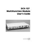
DCX-127 Multi-Function Module
Figure 2. DCX-127 Multi-Function Module
The DCX-127 Multi-Function Module contains an autoranging 4-1/2
digit dc voltmeter-ohmmeter, two 20-bit programmable dc voltage sources,
21 bits of digital I/O, and three 8-bit programmable auxiliary output ports
for device control or status indicators. Typical applications include A/D and
D/A converter testing, VCA gain control linearity, VCA distortion, amplifier
dc offset and power supply checks, power amplifier load switching control,
loudspeaker voice coil resistance measurements, temperature
measurements, and test fixture control.
The meter features 200 mV–500 V and 200 W–2 MW ranges, fully
floating and guarded for accurate measurements in the presence of large
common mode voltages. Resistance measurements can be made using
either 4-wire or 2-wire techniques. Readings can be offset and scaled by
the software.
The two independently programmable dc sources have a ±10.5 V
bipolar range with 20 mV resolution and monotonicity to 40 mV (19 bits).
The software can sweep either dc source.
The DCX-127 also contains a simplified 8-bit program control interface
that can be defined to execute any pre-defined keystroke sequence. This
can be used to run different software procedures based upon switch
closures.
6
Getting Started with Cascade Plus
Overview
Chapter 1: Introduction
PSIA-2722 Programmable Serial Interface Adapter
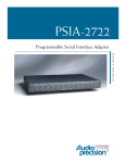
Figure 3. PSIA-2722 Programmable Serial Interface Adapter
The PSIA-2722 Programmable Serial Interface Adapter provides a
means of interfacing System Two Cascade or Cascade Plus to a variety of
data acquisition, reconstruction and communication hardware that use a
serial bus for data exchange. This greatly increases the system’s flexibility
in interfacing to serial systems for a wide range of tests and measurements.
The PSIA consists of a parallel-to-serial transmitter and an independent
serial-to-parallel receiver under APWIN software control.
A serial interface adapter such as PSIA-2722 is required to transmit or
receive digital signals and associated clock inputs and outputs for the
non-AES3/IEC60958 serial digital audio formats often encountered in
telecommunications and in converter design and testing. The settings
necessary to configure the PSIA are easily accomplished in software, and
converter-specific setups can be saved, reloaded or downloaded from the
Web.
PSIA-2722 requires APWIN version 2.22 or later software.
Getting Started with Cascade Plus
7
Chapter 1: Introduction
8
Overview
Getting Started with Cascade Plus
Chapter 2
Specifications
Analog Signal Outputs
All System Two Cascade Plus configurations except SYS-2700 contain an
ultra-low distortion analog sine wave generator and two independent transformercoupled output stages.
The SYS-2622 and SYS-2722 configurations also contain a dual-channel D/A
signal generator for enhanced capabilities. Option “BUR” adds analog-generated
sine burst, square wave, and noise signals. Option “IMD” adds analog-generated
IMD test signals.
Unless otherwise noted, all specifications are valid only for outputs ³150 µVrms
[420 µVpp].
Analog Output Characteristics
Source Configuration
Source Impedances
Balanced or CMTST
Unbalanced
Max Floating Voltage
Output Current Limit
Max Output Power into 600 W
Balanced
Unbalanced
Output Related Crosstalk
10 Hz–20 kHz
20 kHz–100 kHz
Selectable balanced, unbalanced, or CMTST
(common mode test)
40 W (±1 W), 150 W1 (±1.5 W), or 600 W (±3 W)
20 W (±1 W) or 600 W (±3 W)
42 Vpk (outputs are isolated from each other)
Typically >80 mA
+30.1 dBm (Rs = 40 W)
+24.4 dBm (Rs = 20 W)
£ –120 dB or 5 µV, whichever is greater
£ –106 dB or 10 µV, whichever is greater
Low Distortion Sine Wave Generator
Frequency Range
Frequency Accuracy
High-accuracy mode
Fast mode
1
10 Hz–204 kHz
±0.03%
±0.5%
200 W ±2 W with option “EURZ”
Getting Started with Cascade Plus
NP0020.0001.000 R3
9
Cables and Adapters
Chapter 2: Specifications
Cables and Adapters
Analog Audio Cables
These cables provide a convenient method to connect Audio Precision
measurement equipment with a device under test. These cable kits consist
of four cables, each with a unique color band at the connector ends to
facilitate identification. The cables are high quality Mogami NEGLEX
super flexible shielded cable, and are 8 ft (2.4 m) long. The cables and
connector shells are satin black, and all connectors have gold plated
contacts.
§ CAB-XMF consists of a set of four XLR male to XLR female cables.
CAB-XBR consists of a set of four cables: two with RCA/PHONO male
to XLR male connectors, and two with RCA/PHONO male to XLR female
connectors. Also provided are four adapters, from RCA female to BNC
male. The cables are wired with pin 2 of the XLR connector as “hot”
(center pin of the RCA connector) and pins 1 and 3 connected to ground
and shield, to agree with the unbalanced wiring convention of Audio
Precision instruments. See Figures 38 and 39.
Figure 38. CAB-XBR cable kit
Getting Started with Cascade Plus
47
Chapter 2: Specifications
Digital Audio Cables
Figure 39. XLR to BNC wiring
Digital Audio Cables
Figure 40. CAB-AES cable set
These cables are designed for digital audio connections using the
AES/EBU format, XLR connectors, 110 W cable, double-shielded for
improved EMI performance.
§ CAB-AES: Set of two AES/EBU cables, 39 in (1 m) long. See Figure
40.
§ CAB-AES2: Set of two AES/EBU cables, 6.5 ft (2 m) long.
§ CAB-AES4: Set of two AES/EBU cables, 13 ft (4 m) long.
§ CAB-DIO: Set of two interface cables, 4.25 ft (1.3 m) long, to
connect between the SYS-2722 rear panel 50-pin ribbon
input/output connectors to a DUT fixture with 0.1 in spaced
2 x 25-pin headers. See Figure 41.
48
Getting Started with Cascade Plus
Digital Audio Cables
Chapter 2: Specifications
Figure 41. CAB-DIO cables
Cable Adapters
§ CAD-RCA: set of 14 RCA/Phono female to BNC male adapters,
intended primarily for use with the SWR-2122U Unbalanced
Switcher.
Digital Control (APIB) Cables
These cables can be used as extensions or replacements for the APIB
cables that come with each switcher or DCX-127.
§ CAB-D0: Extension APIB Interface cable, 20 in (0.5 m).
§ CAB-D2: Extension APIB Interface cable, 6.5 ft (2 m).
§ CAB-D6: Extension APIB Interface cable, 12.7 ft (6 m).
Getting Started with Cascade Plus
49
Chapter 2: Specifications
50
Digital Audio Cables
Getting Started with Cascade Plus
Chapter 3
Hardware Installation
For table top use, the System Two Cascade Plus can be stacked with
switchers or other instruments.
Rack Mounting
There are two styles of rack mount kits available to rack mount
Cascade Plus: fixed, and slide-out.
Fixed Rack-Mounting Brackets
Install the fixed installation rack mounting kit as shown in Figure 42.
The parts required are identified in the table in Figure 43.
Figure 42. Fixed installation rack mounting kit
Getting Started with Cascade Plus
51
Chapter 3: Hardware Installation
Rack Mounting
Figure 43. Parts list for fixed installation rack mounting
Sliding Rack-Mounting Brackets
The slide rack mounting kit is intended to be used with Chassis Track
C-300-S Series non-pivoting solid bearing chassis sections from General
Devices Inc, Indianapolis, IN. These chassis sections are available in
several lengths to fit a wide variety of racks.
Install the sliding installation rack mounting kit as shown in Figure 44.
The parts required are identified in the table in Figure 45.
Figure 44. Sliding rack mount installation kit
Figure 45. Parts list for sliding rack mounting installation
52
Getting Started with Cascade Plus
Rack Mounting
Chapter 3: Hardware Installation
Checking or Changing Power Line Voltage
Housing
Voltage selector card
Indicator pin
Removal notch
Fuse block
Cover
Figure 46. Changing power line voltage
The AC Mains input to each instrument is made through a
connector/fuse block/voltage selector assembly. Before connecting the
power cord, confirm that the input voltage selection is correct for your
power source. An indicator pin shows the selected input voltage in one of
the four holes in the cover (see Figure 46).
To change the input voltage, refer to Figure 46 and proceed as follows:
1. Remove the AC power cord from the AC Mains Connector.
2. Open the cover, using a small blade screwdriver or similar tool. Set
aside the cover/fuse block assembly.
3. Pull the voltage selector card straight out of the housing, using the
indicator pin.
Voltage Selector Card Orientations
100V
90°
120V
90°
230V
90°
240V
Figure 47. Voltage selector card positions
4. Orient the selector card so that the desired input voltage is readable
at the bottom (see Figure 47). Then orient the indicator pin to point
Getting Started with Cascade Plus
53
Chapter 3: Hardware Installation
Rack Mounting
up when the desired voltage is readable at the bottom, with the
indicator pin assembly seated in the notch on the board edge.
5. Insert the voltage selector card into the housing with the printed side
of the card facing toward the connector, and the edge indicating the
desired voltage first.
6. Confirm that the correct fuse is installed for the intended input
voltage (refer to fuse ratings marked on the rear panel). If necessary,
change the fuse type as described in the following section.
7. Replace the cover and verify that the indicator pin shows the desired
voltage.
Fuse Information
The connector/fuse block/voltage selector assembly allows two fusing
arrangements: North American (see Figure 48), and European (see Figure
49). The North American fusing arrangement uses a single type 3AG (0.25
x 1.25 in) SB (“slow blow”) fuse; the European fusing arrangement uses
two 5 x 20 mm IEC-approved type T fuses. Refer to the label on the rear
panel for fuse current ratings.
Jumper bar
Fuse block
Fuse
Cover
100 / 120 V Orientation
Figure 48. North American fusing arrangement
Fuses
Fuse block
Jumper bar
Cover
230 / 240 V Orientation
Figure 49. European fusing arrangement
54
Getting Started with Cascade Plus
Rack Mounting
Chapter 3: Hardware Installation
Changing Fusing Arrangement
To change from one fusing arrangement to the other:
1. Remove the AC power cord from the AC Mains Connector.
2. Open the cover of the connector/fuse block/voltage selector assembly
with a small blade screwdriver or similar tool.
3. On the back of the cover, loosen the Phillips screw two turns, then
remove the fuse block by sliding up, then away from the screw and
lifting from pedestal at the other end (refer to Figure 50).
Fuse
Fuse Block
Screw
Screw Pedestal
Fuse Block
fits into notch
Support Pedestal
Cover
Figure 50. Changing fuse types
4. Invert the fuse holder and reassemble it on the Phillips screw and
pedestal, and tighten the screw.
5. Change or add the correct fuses as necessary (again, refer to rear
panel for the correct fuse current rating).
6. Confirm the line voltage setting as described in the previous section,
then replace the cover.
Proper Environment
All Audio Precision System One, System Two, System Two Cascade and
System Two Cascade Plus products are intended for use indoors, in a
normal environment. Refer to Chapter 2 for temperature range and
humidity specifications.
Getting Started with Cascade Plus
55
Chapter 5: Getting Started with APWIN
Chapter 5
Getting Started with APWIN
This section will get your system up and running and will put results on
the screen for you in mere moments. For more detailed information about
APWIN, System Two Cascade Plus, and all the options available, see the
APWIN User’s Manual or APWIN Help.
If you haven’t done so yet, unpack and install the System Two Cascade
Plus and APWIN software and hardware components. To mount the APIB
interface card, see Chapter 3. To install APWIN software on your
computer, see Chapter 4.
Turn on System Two Cascade Plus with the rocker switch on the front
panel. The blue POWER indicator will light, and you will hear a brief
clatter of relay switches from within the unit.
Now launch APWIN on your computer. You should find a shortcut icon
on your desktop, or choose Start > Programs > Audio Precision
APWIN 2.2 > APWIN 2.2x
Figure 66. Choose hardware dialog box.
Getting Started with Cascade Plus
67
Chapter 5: Getting Started with APWIN
Running Your First Tests
If the dialog box in Figure 66 appears on your screen, APWIN is not
exchanging information with System Two Cascade Plus. Check your APIB
connections and be sure power is applied to System Two Cascade Plus. If
System Two Cascade Plus is not available, you won't be able to perform
the tests described here, but you can run APWIN in Demo Mode to
become familiar with its interface and capabilities.
If Figure 66 did not appear on your screen, you are properly connected
to System Two Cascade Plus. As APWIN initializes, you will see the
APWIN startup screen and hear the relays click once again. The main
APWIN Screen will appear, as shown in Figure 67. Like most Windows
programs, the APWIN Screen has a title bar, a menu bar and a collection
of toolbars.
Figure 67. APWIN screen
The APWIN Screen has five tabbed pages for display of its various test
panels. By default, APWIN launches with the Analog Generator and
Analog Analyzer panels on Page 1, the Sweep panel and an empty Graph
on Page 2, and the Digital I/O panel on Page 3. APWIN panels can be
opened, closed, expanded or contracted (double-click the panel’s title bar)
and placed on any page (or even repeated on several pages).
Running Your First Tests
This section discusses three different ways to use APWIN and System
Two Cascade Plus to test your DUT. (DUT means Device Under Test, the
unit you are subjecting to measurement. Sometimes it’s called the EUT, for
68
Getting Started with Cascade Plus
Running Your First Tests
Chapter 5: Getting Started with APWIN
Equipment Under Test.) First we will run a test manually, then load a saved
test, and finally use the Quick Launch toolbar.
Use balanced or unbalanced connections between your equipment and
System Two Cascade Plus as appropriate. Most professional and broadcast
audio equipment uses balanced connections (“high” and “low” audio
signal lines plus ground for each channel) with “XLR” connectors; most
consumer audio equipment uses unbalanced connections (a “high” audio
signal line plus ground, which also carries the audio “low” signal) with ¼"
phone, RCA or 3.5 mm mini jacks.
System Two Cascade Plus uses both XLR and “banana” connectors
(connected in parallel, with both active in the balanced configuration) to
carry its balanced inputs and outputs. Unbalanced inputs and outputs are
carried on BNC connectors. The balanced and unbalanced designations
on System Two Cascade Plus are mutually exclusive. You must select one
or the other for each input and output.
Figure 68 shows some common cable hookups.
ANALOG OUTPUT A
ANALOG OUTPUT B
Pin 1: GROUND (SHIELD)
Pin 2: BAL+ or UNBAL HI
Pin 3: BAL- or UNBAL LO
ANALOG INPUT A
SYSTEM TWO CASCADE PLUS 2722
UNBAL
UNBAL
R
230Vpk MAX
DUAL DOMAIN
N
Pin 1: GROUND (SHIELD)
Pin 2: BAL+ or UNBAL HI
Pin 3: BAL- or UNBAL LO
DIGITAL OUTPUT
OPTICAL
BAL
OPTICAL
10Vpp MAX
ANALYZER SIGNAL MONITORS
CHANNEL A
CHANNEL B
CHANNEL A
CHANNEL B
READING
Rs=600W
Rs=600W
Rs=600W
Rs=600W
Rs=600W
GENERATOR AUX SIGNALS
SYNC OUTPUT
10Vpp MAX
UNBAL
Pin 1: GROUND (SHIELD)
Pin 2: BAL+ or UNBAL HI
Pin 3: BAL- or UNBAL LO
GENERATOR MONITORS
II
I
BAL
230Vpk MAX
Pin 1: GROUND (SHIELD)
Pin 2: BAL+ or UNBAL HI
Pin 3: BAL- or UNBAL LO
DIGITAL INPUT
II
I
ANALOG INPUT B
UNBAL
TRIG/GATE INPUT
CHANNEL 1
DIGITAL SIGNAL MONITORS
CHANNEL 2
READING 1
READING 2
Rs=600W
Rs=600W
Rs=600W
POWER
UNBAL
UNBAL
5Vpp MAX
5Vpp MAX
O
I
DIGITAL INTERFACE: AES/EBU and CONSUMER
5V
Rs=600W
0V
Rs=600W
Figure 68. Typical balanced and unbalanced connections
Getting Started with Cascade Plus
69