1
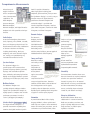
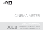
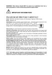
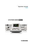
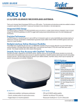
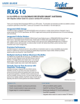
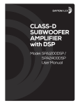
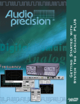
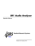
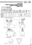
Testing for Optimal Results
ATS-2
Audio Test and Measurement System
Unmatched Value
Turn on ATS-2: Audio Testing to Meet Your Deadline and Budget
Multitone test signal from Generator with flat
spectrum and virtually no distortion and noise.
Note some frequencies in the higher area of the
spectrum are different on each channel to allow
for crosstalk measurements.
Audio Precision’s PC-controlled ATS-2 audio test and measurement system provides
design engineers and technicians with Audio Precision quality and the ability to choose
performance capabilities to match specific needs and budgets. By quickly discovering
and isolating circuit problems with its Harmonic Distortion Analyzer, ATS-2 can
dramatically decrease your time to market. With its Multitone Analyzer, ATS-2 provides
comprehensive solutions to your audio testing challenges by executing five performance
tests in a single acquisition, collating all the data you need to graph any test
result—all in less than one second. And because it’s PC-controlled, ATS-2 allows you to
leverage your existing PC investment.
Multitone Performance Tests
• 2-Channel Frequency Response
• Noise versus Frequency
• Total Distortion versus Frequency
• Interchannel Separation versus Frequency
• Interchannel Phase Response
The interface measurement capability in ATS-2 determines whether or not the signal
from a digital device meets standards and is compatible with other devices. High
Multitone signal received from the device under
test. Note the amplitude of the fundamentals is
representing the response of the device and the
higher signals near the bottom of the spectrum
represent noise and distortion.
performance measurement capabilities include jitter and FFT of jitter, pulse
amplitude, word width, bit activity, sample rate and high-level decoded status bits.
Interface stimulus features simulate real-world degradations to measure the effect on
the device during testing.
Audio Precision also offers a performance option for the ATS-2 that increases the
analyzer bandwidth to 120 kHz and includes complete digital interface
signal measurement and analysis, including waveform display and
eye pattern tests.
Frequency Response
Noise vs. Frequency
Distortion vs. Frequency
Interchannel Phase
Response
Interchannel Crosstalk
High Performance,
Unmatched Value
High Performance, Simplified
ATS-2 offers dual analyzers to quickly
The ATS-2 provides design engineers and
identify and repair the problems that occur
technicians with Audio Precision quality
during the design and manufacture of
and the ability to choose performance
audio equipment. The Harmonic Distortion
capabilities to match specific needs and
Analyzer provides insight into a variety of
circuit malfunctions, allowing an engineer
Reach Your Market Faster
or technician to isolate circuit problems
budgets. By getting you to market faster
through a dramatically faster testing
process, ATS-2 allows for a quicker return
and fix them quickly. The Multitone
The rapid, single acquisition testing of
Analyzer—an FFT analyzer coupled with an
ATS-2’s Multitone Analyzer saves you
arbitrary waveform generator—performs a
the time and expense of individually
variety of performance tests quickly.
setting up and executing each test. It
Without multitone, those tests must be set
eliminates errors by providing a
up and executed one at a time.
comprehensive set of answers to your
on investment on your developments.
And by leveraging your existing PCs,
ATS-2 increases your asset utilization,
helping to improve your design’s
financial performance. And the inherent
performance questions with one easy
With PC-controlled functionality, ATS-2
setup. By decreasing the time spent on
allows you to leverage your existing PC
finding and fixing circuit problems,
investment and gives you a familiar
ATS-2 decreases your time to market.
high-reliability of the ATS-2 is backed up
by a three-year warranty, the best in the
industry.
interface to:
• Monitor instruments
• Graphically display test data
• Manage files for test setups
• Easily share and archive data
• Generate reports with your preferred
word processing application; and
• Export test data to analysis
programs—such as MATLAB®—for
extended analysis.
The PC-controlled ATS-2 lets you enjoy the
Digital interface signal analysis—Eye
Pattern test.
longevity of Audio Precision test and
measurement equipment without sacrificing
the regular performance upgrades available
with your PC platform.
Digital interface signal analysis—Interface Waveform Jitter,
cell-by-cell.
Turn on ATS-2: Audio Testing to Meet Your Challenges
High Performance, by Design
Signal Generators
Key ATS-2 features
• Analog and digital inputs and
ATS-2 sets a new mark in value for
ATS-2 has two independent signal
computer-controlled audio testing
generators, one for analog output and one
systems. ATS-2 puts a broad set of
for digital output. The two generators can
capabilities, high measurement
each create a large number of test signals,
performance and a proud legacy of
including:
excellence into a light-weight, compact
• Sine waves as: mono, stereo,
and affordable general purpose instrument
suited to the design lab, broadcast facility
or production line.
phase-shifted, tone bursts, dual.
• Noise
• Square waves
outputs.
• Generation of test signals for both
analog and digital devices.
• Multi-functioned audio analysis,
spectrum analysis, multitone
analysis, detailed harmonic analysis,
optional interface analysis.
• Full complement of graphing and
report options.
• Special waveforms, including polarity,
a pass-through function and special
digital waveforms
• Arbitrary waveforms, including
Multitone signals (predefined or user
defined using supplied utility).
Inputs and Outputs
ATS-2 offers both balanced and unbalanced connections for both analog and digital signal domains. For digital signals, the balanced
connections satisfy the electrical and mechanical aspects of AES3 and IEC60958-4, offering dual-connector mode as well. The
unbalanced connections satisfy AES3id and are also suitable for S/PDIF signals. Optical connectors are also provided.
Signals in either the analog or digital domain can be
characterized for audio performance with the Audio Analyzer
that provides a comprehensive set of measurement functions
including:
• Amplitude
• Noise (weighted, band limited, or narrow band)
• 2-Channel Amplitude Ratio
• Crosstalk (Channel Separation)
• THD+N (both ratio and absolute amplitude)
• SMPTE/DIN Intermodulation Distortion
• Phase
Comprehensive Measurements
A broad range of
detail. It provides information
analysis functions
about signal jitter including jitter
offer a comprehensive
amplitude, jitter waveform, jitter spectrum.
suite of measurement
The Eye Pattern display is a concise, easy to
capabilities. The
interpret measure of digital interface
Audio Analyzer,
Spectrum Analyzer,
Five separate Analyzers cover
all measurements.
performance. Powerful analytical and
statistical analysis is provided with
Multitone Analyzer,
interface amplitude histograms, interface
Harmonic Analyzer, and Digital Interface
pulse width histograms, interface bit-width
Analyzer each offer powerful and unique
histograms, and Jitter histograms.
features.
Broad Digital Signal analysis capability shown
by the nine graphs depicted here.
Harmonic Analyzer
Audio Analyzer
The Harmonic
A two-channel analyzer that measures
Analyzer provides a
simple user input, and
level, frequency, noise, THD+N, crosstalk,
detailed look at
automatically
phase, and frequency-selective level. The
individual harmonic
measurement functions offer combinations
distortion products.
of detector selections and filtering
Particularly useful
including band limiting, band pass,
with the sweep facility to generate graphs of
with simple trouble
weighting, and notch. Detectors may be
individual harmonics versus frequency.
ticket up to a
Harmonic Analyzer panel and graph
of individual harmonic amplitude
versus frequency.
generate anything
from a simple
Pass/Fail condition
multipage graphical
rms, average, and peak allowing any
Extensive scripting
language and a
sophisticated editor allow
easy creation of
automated test
Sweeps and Graphs
report.
Most ATS-2 settings
A “learn mode” lets
Spectrum Analyzer
and readings can be
even non-programmers create
The Spectrum Analyzer is a
designated as
sophisticated test procedures
general-purpose FFT instrument that
independent or
incorporating OLE commands.
generates frequency-domain (spectrum)
dependent variables
displays, with selectable acquisition
and be plotted
times, windowing and averaging functions.
against one another
Display can be toggled between spectrum
using the
(frequency) and oscilloscope (time) views.
comprehensive ATS-2
switchers can expand the number of
sweep and graph functions. Extensive
channels in groups of 12. An external
Multitone Analyzer
attribute controls allow a wide variation of
multi-function accessory can add DC volts
The Multitone Analyzer uses
the visual appearance of the graphs,
and ohms measurement, DC voltage
specially-designed multitone stimulus
including color, axis dimensions, and size.
sources, and utility input and output
signals with specialized FFT analysis to
Flexible export capability allows integration
control for push buttons and relays.
rapidly capture a complete suite of audio
of graphs in various report programs.
international standard to be met.
Flexible sweep and graph controls
allow up to 6 simultaneous
measurements to be graphed at
once with extensive selection of
variable elements and graph
presentation.
For measurement situations where more
than two channels are required, outboard
Enterprise collaboration
performance parameters in under a
second. (See page 2 for examples)
Extensibility
Automation
PC-based ATS software allows easy
Ò
A powerful Visual Basic -like scripting
collaboration in a team environment.
Interface Analysis
language, AP Basic, allows sophisticated
Email test procedures, test data, and
The Digital Interface Analyzer is a
multi-step test sequences to be automated.
graphs to quickly duplicate test results,
powerful measurement capability that
Create self-running test procedures, test for
study test data, or publish reports
examines the digital interface signal in
conformance to pre-defined limits, allow
regardless of location.
SIGNAL GENERATOR OUTPUTS
Waveforms
Frequency Range
Frequency Accuracy
Frequency Resolution
Amplitude Range
Balanced
Unbalanced
Amplitude Accuracy
Amplitude Resolution
Analog
Sine Family (Normal, Var Phase, Stereo,
Dual, Shaped Burst, EQ), IMD
(SMPTE/DIN 4:1, 1:1) Square, Noise,
Arbitrary Waveform (Multitone), Special
(Polarity, Pass Thru)
2 Hz to 61.6 kHz
±0.0002%
Digital
Sine Family (Normal, Var Phase,
Stereo, Dual, Shaped Burst, EQ,
Burst, Offset) IMD (SMPTE/DIN
4:1, 1:1) Square, Noise,
Arbitrary Waveform (Multitone),
Special (Polarity, Pass Thru,
Monotonicity, J-Test, Walking
Ones, Walking Zeros, Constant
Value, Random)
2 Hz to .50 x SR (Sample Rate)
SR/2^23
<250 mVrms to 16.00 Vrms [+26.3 dBu]
<250 mVrms to 8.00 Vrms [+20.28 dBu]
±0.09dB [±1.0%]
0.007 dB or 0.60 mVrms, whichever is
larger
SR/2^23
±0.001 dB
0.000001% [-160 dB]
THD+N1
20 Hz-20 kHz
£(0.0009% [-101 dB] + 1.6 mV)
Frequency Range
10 Hz–20 kHz
Risetime
Typically 2.0 ms
LF Tone Range
HF Tone Range
Mix Ratio
Residual IMD2
40 Hz to 500 Hz
2 kHz to 60 kHz
4:1 or 1:1(LF:HF)
£0.0025% [-92 dB]
40 Hz to 500 Hz
2 kHz to 0.47 x SR
4:1 or 1:1(LF:HF)
Length
256 to 16384 points per channel
Frequency Range
Frequency Resolution
DC to 0.47 x SR
SR / Length
256 to 16384 points per
channel
DC to 0.47 x SR
SR / Length
White, Pseudo-Random, Rectangular
PDF, 30 kHz or 60 kHz BW
Burst
Shaped burst: Raised cosine
Source Configuration
Balanced (XLR), Unbalanced (XLR and
BNC), or Common Mode Test (XLR)
Source Impedances (Rs)
Balanced or Common
Mode Test
Unbalanced
Output Current Limit
Max Output Power into 600W
Balanced
Unbalanced
Output Related Crosstalk
(20Hz- 20kHz)
Formats
Balanced (XLR)
Unbalanced (BNC)
Optical (ToslinkÒ)
Sample Rate Range
Word Width
Output Amplitude
Balanced into 110W
Unbalanced into 75W
Optical (ToslinkÒ)
Audio Analyzer
Resolution
w/Performance Option
Sample Rate
w/Performance Option
Flatness
±0.01 dB (20 Hz-20 kHz, 500 Hz ref)
ANALYZER
2 Hz to SR / 6, in even integer
sub-multiples of SR
N/A
Input Ranges
Maximum Rated Input
Input Impedance
Balanced
Unbalanced
CMRR3
355mVp to 5.6Vp range
11.2 Vp to 200Vp range
Input Related Crosstalk
Formats
Balanced (XLR)
24-bit sigma-delta
16-bit sigma-delta
28.8ks/s to 108ks/s variable; or
65.536ks/s fixed
8-24 bits
28.8kHz to 100kHz AES/EBU;
64kHz-200kHz Dual Connector
AES/EBU
56ks/s to 215ks/s variable; or
131.072ks/s or 262.144 ks/s fixed
355 mVp to 200 Vp in 6.02 dB steps
200Vp, 140Vrms (dc to 20kHz);
overload protected in all ranges
Nominally 200 kW
Nominally 100 kW
³80 dB, 10 Hz–20 kHz
³50 dB, 10 Hz–1 kHz
£(-100 dB +3 mV), at 20 kHz
AES/EBU (per AES 3-1997);
SPDIF-EIAJ; Optical
SPDIF-EIAJ per IEC 60958
Per IEC 60958-3
28.8 kHz to 108 kHz per
connector
8 to 24 bits
Unbalanced (BNC)
Optical (ToslinkÒ)
Sample Rates
Word Width
<1 mV-140 Vrms [-118 dBu to + 45.1
dBu]
±0.09 dB [±1.0%]
-120 dBFS to 0 dBFS (usable to
-140 dBFS)
±0.002 dB [±0.023%]
±0.01 dB, 20 Hz to 20 kHz
±0.01dB, 20 Hz to 20 kHz;
±0.1 dB, 20k to 120 kHz
RMS, FAST RMS, or QPK per IEC 468
(CCIR)
±0.002 dB, 10 Hz to 0.45xSR
Range
With Performance Option
Accuracy
Resolution
> 10 Hz to 30 kHz (SR = 65.536 kS/s)
> 10 Hz to 120 kHz
±0.0002% [2 PPM]
0.00001% of SR [0.007 Hz at 65.536
kS/s]
< 10 Hz to 0.47xSR
Phase Measurement
Measurement Ranges
Accuracy
10 Hz to 5 kHz
5 kHz to 20 kHz
20 kHz to 50 kHz (With
Performance Option)
Resolution
Analog
180, -90 to +270, or 0 to +360 deg
Digital
SAME
2 deg, 10 Hz to 0.45xSR
0.01 deg
SAME
AES3 per AES3-1997
SPDIF-EIAJ per IEC 60958
Per IEC 60958-3
28.8 kHz to 108 kHz per
connector
8 to 24 bits
A-weighted
Dolby 2K
IEC 468 (CCIR)
20 kHz LP
£ 1.2 mV rms
£ 2.0 mV rms
£ 5.0 mV rms
£ 1.6 mV rms
£ -142 dBFS
£ -134 dBFS
£ -127 dBFS
£ -140 dBFS
Range 0 to 5.10 Vpp
Range 0 to 1.275 Vpp
Nominal intensity, not variable
Fundamental Range
Measurement Range
Accuracy
10 Hz to 0.47xSR
0 to 100%
±0.3 dB, 10 Hz to 0.45xSR
(no filters selected)
£ 0.0009% [-101 dB] + 1.6 mV (with
20 kHz LP)
SAME
SAME
SAME
White, Pseudo-Random White,
Rectangular PDF, Bandwidth
0.50 x SR
Shaped burst: Rectangular
envelope, raised cosine
Nominally 40W or 150W (200W with
option EURZ)
Nominally 20W or 50W
Typically 50 mA
+24.1 dBm (Rs = 40W)
+18.4 dBm (Rs = 20W)
£(-100 dB + 3 mV)
Measurement Range
Accuracy (1 kHz)
Flatness4
“HiRes” A/D
“HiBW”5 A/D
Detection
Residual THD+N
1-System specification including contributions from both generator and analyzer, 20 kHz measurement bandwidth.
2-System specification with 60 Hz/7 kHz or 250 Hz/8 kHz test signal combinations and Vin ³ 200 mV.
3-CMRR performance below 50 Hz degrades with AC coupling.
4-1 kHz ref. Flatness derates above 5 kHz by an additional ±0.02 dB in the 22.4 V, 45 V, 90 V, and 200 V input ranges.
5-Requires High Performance Option.
SAME
SAME
SAME
2 deg
3 deg
4 deg
One filter from each of the following three groups may be enabled (3 filters total)
Low Pass Group
Fs/2 (no BW limiting)
20 kHz (6-pole elliptic, 0.1 dB ripple, 110 dB stopband
15 kHz (6-pole elliptic, 0.1 dB ripple, 110 dB stopband
User Defined (6-pole maximum)
High Pass Group
< 10 Hz (4-pole)
22 Hz (4-pole Butterworth)
100 Hz (4-pole Butterworth)
400 Hz (4-pole Butterworth, or 10-pole
elliptic if no other filters are enabled)
User Defined (4-pole maximum)
Weighting Filter Group
None
ANSI-IEC “A” weighted, per IEC 179
IEC 468 (CCIR) Qpk
Dolby 2K (CCIR-ARM)
C-message per IEEE 743-1978
CCITT per Rec 0.41
“F” weighted per 15 phon loudness contour
HI-2 Harmonic weighting
User Defined (8-pole maximum)
Tuning Range
Bandpass Response
Accuracy (at center frequency)
Residual Noise
10 Hz to 5 kHz
5 kHz to 20 kHz
20 Hz to 0.47xSR
10-pole, Q=19
±0.2 dB
SMPTE (DIN) IMD Function
Test Signal Compatibility
Analog
Any combination of 40 Hz to 250 Hz
(LF) and 2 kHz to 0.45xSR (HF), mixed
in any ratio from 1:1 to 5:1 (LF:HF)
Amplitude modulation products of the
HF tone.
Measurement bandwidth is typically 20
Hz to 750 Hz
0 to 20%
±0.5 dB
£0.0025% [-92 dB]
IMD Measured
Measurement Range
Accuracy
Residual IMD6
FFT Analyzer
Acquisition Length
Transform Length
Windows
Amplitude Accuracy
(Flat-top window)
Phase Accuracy7
Averaging
Number of Averages
Algorithm
Residual Distortion
Analog Alias Rejection
Standard (“HiRes” A/D)
Performance Option
(“HiBW” A/D)
Multitone Analyzer
Acquisition and Transform
Lengths
Frequency Resolution
Residual Distortion
£0.5 mV [-124 dBu]
£1.0 mV [-118 dBu]
SAME
SAME
±0.2 dB
£-150 dBFS
Digital
SAME
SAME
£0.00003% [-130 dB] at 0 dBFS
£0.0003% [-110 dB] at -25 dBFS
Analog
Digital
800 to 256 k samples in 11 steps
SAME
256 to 32768 samples in binary steps
SAME
None
None-move-to-bin-center
Hann
Hamming
Blackman-Harris (4-term, -92 dB sidelobes)
Equiripple (AP design with -160 dB sidelobes)
Flat-top
Gaussian
Rife-Vincent 4-term
Rife-Vincent 5-term
±0.10 dB [±1.2%]
±0.001 dB [±0.012%]
±0.5 deg, 10 Hz to 5 kHz
±1 deg, 5 kHz to 20 kHz
±2 deg, 20 kHz to 50 kHz
(with Performance Option)
±0.05 deg, 10 Hz to 0.45xSR
1 to 4096 in binary steps
Power-based (frequency domain)
Synchronous (time domain)
£-105 dB, SR=65 kS/s
£-90 dB, SR=262 kS/s (with
Performance Option)
SAME
Harmonic Distortion Analyzer
Harmonic Sum Range
Amplitude Accuracy
Analog
Any combination of 2nd through 15th
within the range of 20 Hz to 0.498*SR
±(0.10 dB + 0.3 mV)
Residual Distortion
“HiRes” A/D
“HiBW” A/D5
£-105 dB, SR £ 65KS
£-90 dB
SYNC/Reference Input
Signal Compatibility
Digital
±0.001 dB, 0 to -80 dBFS;
±0.01 dB, -80 to -120 dBFS;
±0.10, -100 to -120 dBFS
-150 dB
AES3
Video
Squarewave
Auxiliary Signals
Monitor Outputs
Trigger Input
Trigger Output
Digital Interface
Input Sample Rate
Input Voltage
Balanced (XLR)
Unbalanced (BNC)
Jitter Amplitude (peak
calibrated)
50 – 100 kHz BW
other BW selections
Jitter Frequency Range
Jitter Accuracy (500 Hz)
Jitter Flatness8
Residual Jitter9
Jitter Spectrum
Analyzer
±0.0003% [±3 PPM] internal ref
±0.0001% [±1 PPM] external ref
Generator
200 mV to 5.10 Vpp, ±(10% + 50 mV)
100 mV to 1.275 Vpp, ±(10% + 12 mV)
0.05 to 0.1275 UI in 0.0005 UI steps
0.130 to 1.275 UI in 0.005 UI steps
1.30 to 12.75 UI in 0 05 UI steps
0 to 3.00 UI, ±(10% + 2 ns)
0 to 1.00 UI, ±(10% + 2 ns)
±1 dB, 100 Hz to 20 kHz
£ 2 ns [0.012 UI at 48 kS/s, 0.024 UI
at 96 kS/s]
Spurious products are typically .003 UI
[-50 dBUI] or 30 dB below jitter signal,
whichever is larger
Channel Status Bits
Full implementation per IEC 60958,
English language decoded, common to
both channels
Formats
Validity Flag
Professional or consumer, or Direct Hex
source
Displayed for each channel
Parity; Signal Confidence;
Receiver Lock; Coding Error
Displayed for total signal (both
channels combined)
20 Hz to 200 kHz, 0.1 Hz
resolution
±(10% + 2ns)
±1 dB, 100 Hz to 20 kHz
£ 2.0 ns [0.012 UI at 48 kS/s,
0.024 UI at 96 kS/s]
Spurious products are typically
.003 UI [-50 dBUI] or 30 dB
below jitter signal, whichever is
larger
Full implementation per IEC
60958, English language
decoded, common to both
channels
Selectable-set or cleared,
common to both channels
AUXILIARY SIGNALS
Two Analyzer Input Monitors; Two Analyzer Reading Monitors; Trigger Output that can be selected from
one of several sources including Generator Analog Sync, Digital Sync Output, and several others
£-180 dB
Typically >115 dB for signals >0.554xSR
Typically > 85 dB for signals >0.540xSR
Analog
512 to 32768 samples in binary steps
Digital
SAME
SR / Length [2.0 Hz with SR = 65.536
kS/s and Length = 32,768]
£-105 dB, SR = 65 kS/s
£-90 dB, SR = 262 kS/s (with
Performance Option)
-140 dBFS
SAME
AUDIO MONITOR
Internal speaker and phone jack for external speaker or headphone. Software volume control. Power
Output, typically 1 Watt.
GENERAL / ENVIRONMENTAL
Power Requirements
Temperature Range
Humidity
EMC10
Dimensions
Weight
Safety
100/120/230/240 Vac (-10% +6%), 50-60 Hz, 75 VA max
5°C to +45°C Operating; -40°C to +75°C Storage
90% RH to at least +40°C (non-condensing)
Complies with 89/336/EEC, CISPR 22 (class B), and FCC 15 subpart J (class B)
18.8 x 3.0 x 14.2 inches [42.7 x 7.6 x 36.1 cm]
Approximately 14.8 lbs [6.7 kg] unpacked
Complies with 73/23/EEC, 93/68/EEC, and EN61010-1 (1990) +
Amendment 1 (1992) + Amendment 2 (1995). Installation Category II,
Pollution Degree 2
6-System specification with 60 Hz/7 kHz or 250 Hz/8 kHz test signal combinations and Vin ³ 200 mV.
7-Both analyzer input channels must have same coupling (AC or DC) selection. Analog accuracy is valid for any input signal amplitude ratio up to ±30 dB.
8-System specification including contributions from both analyzer and generator. Valid at 32.0, 44.1, 48.0, 65.536, 88.2, and 96.0 kS/s only. Flatness may degrade at other sample rates.
9-System specification valid only if (1) the jitter generator amplitude is turned off; (2) the digital input is ³ 1.0 Vpp (XLR) or ³ 250 mVpp (BNC); and (3) the analyzer is set for 700 Hz–100 kHz bandwidth.
10-Emission and immunity levels are influenced by the shielding performance of the connecting cables. EMC compliance was demonstrated using Audio Precision part numbers CAB-XMF and CAB-AES2.
Configuration and Ordering Guide:
The standard ATS-2 comes with all control software and interface
hardware to connect to your PC. The optional Performance Option can
be added to provide a high bandwidth analysis capability and serial
digital interface measurements. The Audio Analyzer, Harmonic
Analyzer, FFT Analyzer, and Multitone Analyzer bandwidths are
increased from 30 kHz to 120 kHz. The Digital Interface Analyzer adds:
Options & Ordering Information
ATS-2
Options for ATS-2
ATS2-PERF
ATS2-RAK
ATS2-CAS
Jitter Spectrum analysis, Jitter Waveform, Interface Spectrum analysis,
EWP-ATS2
Interface Waveform (Oscilloscope), Eye pattern, Interface amplitude
MAN-ATS2
histogram, Interface Rate histogram, and Interface bit-width
histogram. All other features and capabilities are identical.
ATS-2 connects to your PC with one of two possible interfaces. The
PC-controlled Audio Test System with APIB interface
Interface Control Packages (select one at time of order)
ATS2-PCI
PCI interface card for ATS-2 (not for Win 95)
ATS2-PCMCIA
PCMCIA interface card for ATS-2
Performance Option for ATS-2
Rack mount kit for ATS-2
Protective soft carrying case for ATS-2 (see picture
below)
Three-Year Extended Warranty (Adds three more years to
standard three-year warranty included with instrument)
Additional ATS-2 Getting Started Manual and ATS-2
User’s Manual (one of each is included with instrument)
Additional Interface Control Packages (to control instrument from more than one computer)
PCI-WIN-KITATS2
PCI ATS interface kit for ATS-2. Includes PCI ATS
interface card, cable, ATS software, User Manual, and
Getting Started Manual
PCM-WIN-KTSATS2
PCMCIA ATS interface kit for ATS-2. Includes PCMCIA ATS
interface card, cable, ATS software, User Manual, and
Getting Started Manual
standard interface uses a PCI card. As an option, this can be
changed to a PCMCIA card.
Soft carrying case option. Padded interior protects
your ATS-2, and has an extra pocket for your
notebook computer, documentation, and cables.
Testing for Optimal Results
5750 SW Arctic Drive
Beaverton, Oregon 97005
Tel 503-627-0832 Fax 503-641-8906
US Toll Free 1-800-231-7350
email: [email protected]
web: audioprecision.com
IV0414132534
0057.0001 r0