1
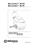
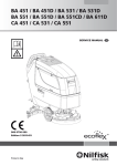
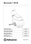
MicromaticTM 13E
SERVICE MANUAL
Advance model: 9087230020
9097511000(1)2008-04
SERVICE MANUAL
ENGLISH
TABLE OF CONTENTS
GENERAL INFORMATION............................................................................................................................................... 2
CONVENTIONS............................................................................................................................................................................... 2
MACHINE LIFTING.......................................................................................................................................................................... 2
MACHINE TRANSPORTATION........................................................................................................................................................ 2
OTHER REFERENCE MANUALS.................................................................................................................................................... 2
SAFETY............................................................................................................................................................................................ 2
GENERAL SAFETY PRECAUTIONS............................................................................................................................................... 3
TECHNICAL DATA............................................................................................................................................................................ 5
DIMENSIONS................................................................................................................................................................................... 6
SCHEDULED MAINTENANCE........................................................................................................................................................ 7
SCHEDULED MAINTENANCE TABLE............................................................................................................................................ 7
MACHINE NOMENCLATURE.......................................................................................................................................................... 8
SOLUTION SYSTEM...................................................................................................................................................... 11
SOLUTION TANK CLEANING.........................................................................................................................................................11
SOLUTION FILTER CLEANING......................................................................................................................................................11
SOLUTION PUMP DISASSEMBLY/ASSEMBLY............................................................................................................................ 12
TROUBLESHOOTING.................................................................................................................................................................... 13
BRUSH DECK SYSTEM................................................................................................................................................. 15
BRUSH MOTOR ELECTRICAL INPUT CHECK............................................................................................................................. 15
BRUSH MOTOR DISASSEMBLY/ASSEMBLY............................................................................................................................... 16
DRIVING BELT CHECK/REPLACEMENT/ADJUSTMENT............................................................................................................ 17
TROUBLESHOOTING.................................................................................................................................................................... 18
RECOVERY WATER SYSTEM....................................................................................................................................... 19
RECOVERY SYSTEM CLEANING................................................................................................................................................. 19
VACUUM SYSTEM MOTOR ELECTRICAL INPUT CHECK.......................................................................................................... 20
VACUUM SYSTEM MOTOR CARBON BRUSH CHECK AND REPLACEMENT.......................................................................... 21
VACUUM SYSTEM MOTOR DISASSEMBLY/ASSEMBLY............................................................................................................ 22
BRUSH/PAD-HOLDER DECK AND SQUEEGEE CLEANING/CHECK – SQUEEGEE DISASSEMBLY/ASSEMBLY................... 23
BRUSH/PAD-HOLDER DECK AND SQUEEGEE DISASSEMBLY/ASSEMBLY............................................................................ 24
TROUBLESHOOTING.................................................................................................................................................................... 25
OTHER SYSTEMS.......................................................................................................................................................... 27
UPPER FRAME DISASSEMBLY/ASSEMBLY................................................................................................................................ 27
SCREW AND NUT TIGHTENING CHECK..................................................................................................................................... 28
ELECTRICAL SYSTEM.................................................................................................................................................. 29
COMPONENT LAYOUT................................................................................................................................................................. 29
WIRING DIAGRAM......................................................................................................................................................................... 30
MicromaticTM 13E
9097511000(1)2008-04
1
ENGLISH
SERVICE MANUAL
GENERAL INFORMATION
CONVENTIONS
Forward, backward, front, rear, left or right are intended with reference to the operator’s position, that is to say in operating position
with the hands on the handlebar.
MACHINE LIFTING
WARNING!
Do not work under the lifted machine without supporting it with safety stands.
MACHINE TRANSPORTATION
WARNING!
Before transporting the machine, make sure that:
–– All covers are closed.
–– The machine is securely fastened to the means of transport.
OTHER REFERENCE MANUALS
The following manuals are available at Nilfisk Literature Service Department:
–– User Manual MicromaticTM 13E - Form Number 9097508000
–– Spare Parts List MicromaticTM 13E - Form Number 9097509000
SAFETY
The following symbols indicate potentially dangerous situations. Always read this information carefully and take all necessary
precautions to safeguard people and property.
DANGER!
It indicates a dangerous situation with risk of death for the operator.
WARNING!
It indicates a potential risk of injury for people.
CAUTION!
It indicates a caution or a remark related to important or useful functions.
Pay careful attention to the paragraphs marked by this symbol.
NOTE
It indicates a remark related to important or useful functions.
CONSULTATION
It indicates the necessity to refer to the User Manual before performing any procedure.
2
9097511000(1)2008-04 MicromaticTM 13E
SERVICE MANUAL
ENGLISH
GENERAL INFORMATION
GENERAL SAFETY PRECAUTIONS
Specific warnings and cautions to inform about potential damages to people and machine are shown below.
DANGER!
–– Always disconnect the power supply cable when the machine is not in use, before performing maintenance
procedures, before replacing the brush/pad-holder and before opening any access panel.
–– This machine must be used by properly trained and authorized personnel only. Children or disabled people
cannot use this machine.
–– Do not wear jewelry when working near electrical components.
–– Do not work under the lifted machine without supporting it with safety stands.
–– Do not operate the machine near toxic, dangerous, flammable and/or explosive powders, liquids or vapours.
WARNING!
–– The machine power supply cable is grounded and the relevant plug is grounded too. In case of machine
malfunction or breakdown, grounding connection reduces the risk of electric shock.
–– The power supply cable plug must be connected to an appropriate outlet, which is grounded according to
law in force.
–– Improper connection can cause electric shock. Consult a qualified technician to make sure that the outlet is
properly grounded.
–– Do not tamper with the power supply cable plug. If the power supply cable plug cannot be connected to the
outlet, have new grounded outlet installed by a qualified technician, according to the law in force.
–– Before connecting the power supply cable to the electrical mains, check that frequency and voltage, shown
on the machine serial number plate (1), match the electrical mains voltage.
–– Do not unplug the machine by pulling the supply cable. To unplug, grasp the plug, not the cable.
–– Do not handle the plug or the machine with wet hands.
–– Turn off all controls before unplugging.
–– Regularly check the power supply cable for damages, cracks, cuts, etc. If the power supply cable is
damaged, replace it immediately.
–– To avoid any risk, if the power supply cable is damaged, contact the Nilfisk Service Center or a qualified
technician.
–– Do not pull or carry the machine by the power supply cable and never use the power supply cable as a
handle. Do not close a door on the power supply cable, or pull the power supply cable around sharp edges
or corners. Do not run the machine on the power supply cable.
–– The brushes must not come into contact with the power supply cable.
–– Keep the power supply cable away from heated surfaces.
–– To reduce the risk of fire, electric shock, or injury, do not leave the machine unattended when it is plugged
in. Disconnect the machine from the electrical mains when not in use and before performing maintenance
procedures.
–– Always protect the machine against the sun, rain and bad weather, both under operation and inactivity
condition. Store the machine indoors, in a dry place.
–– Do not allow to be used as a toy. Close attention is necessary when used near children.
–– Use only as shown in this Manual. Use only Nilfisk’s recommended accessories.
–– Take all necessary precautions to prevent hair, jewelry and loose clothes from being caught by the machine
moving parts.
–– Do not leave the machine unattended without being sure that it cannot move independently.
–– Do not use the machine on slopes with a gradient exceeding the specifications.
–– Do not use the machine in particularly dusty areas.
–– While using this machine, take care not to cause damage to people or objects.
–– Do not bump into furniture, shelves or scaffoldings, especially where there is a risk of falling objects.
–– Do not put any can containing fluids on the machine.
–– The machine operating temperature must be between +32°F and +104°F (0°C and +40°C).
–– The machine storage temperature must be between +32°F and +104°F (0°C and +40°C).
–– The humidity must be between 30% and 95%.
–– Do not use the machine as a means of transport.
–– Do not use the machine on slopes with a gradient exceeding the specifications.
–– Do not allow the brush/pad to operate while the machine is stationary to avoid damaging the floor.
MicromaticTM 13E
9097511000(1)2008-04
3
ENGLISH
SERVICE MANUAL
GENERAL INFORMATION
WARNING!
–– In case of fire, use a powder fire extinguisher, not a water one.
–– Do not tamper with the machine safety guards and follow the ordinary maintenance instructions
scrupulously.
–– Do not allow any object to enter into the openings. Do not use the machine if the openings are clogged.
Always keep the openings free from dust, hairs and any other foreign material which could reduce the air
flow.
–– Do not remove or modify the plates affixed to the machine.
–– This machine cannot be used on roads or public streets.
–– Pay attention during machine transportation when temperature is below freezing point. The water in the
recovery tank or in the hoses could freeze and seriously damage the machine.
–– Use brushes and pads supplied with the machine and those specified in the User Manual. Using other
brushes or pads could reduce safety.
–– In case of machine malfunctions ensure that these are not caused by a lack of maintenance. Otherwise,
request assistance from the authorised personnel or from an authorised Service Center.
–– If the machine
• does not work properly
• is damaged
• has water or foam leaks
• has been left outdoors exposed to bad weather conditions
• is wet or has been dropped into water turn it off immediately and contact the Nilfisk Service Center or a
qualified technician.
–– If parts must be replaced, require ORIGINAL spare parts from an Authorised Dealer or Retailer.
–– To ensure machine proper and safe operation, the scheduled maintenance shown in the relevant chapter of
this Manual, must be performed by the authorised personnel or by an authorised Service Center.
–– Carefully read all the instructions before performing any maintenance/repair procedure.
–– Do not wash the machine with direct or pressurised water jets, or with corrosive substances.
–– The machine must be disposed of properly, because of the presence of toxic-harmful materials (electronic
components, etc.), which are subject to standards that require disposal in special centres (see the Scrapping
chapter).
4
9097511000(1)2008-04 MicromaticTM 13E
SERVICE MANUAL
ENGLISH
GENERAL INFORMATION
TECHNICAL DATA
General
MICROMATIC 13E - 115 Volt
Min/max machine length at the handlebar
28.1/44.1 in (715/1,120 mm)
Machine width with squeegee
15.1 in (385 mm)
Machine - brush deck width
15.1 in (385 mm)
Maximum machine height with adjustable handlebar
39.4 in (1.000 mm)
Turning radius
45.3 in (1,150 mm)
Total machine weight
48.5 lb (22 kg)
Cleaning width
12.9 in (330 mm)
Central wheel diameter
7.0 in (180 mm)
Brush diameter
6.5 in (165 mm)
Brush number
No. 2 brushes/pads
Squeegee system
Fixed on deck
Straight squeegee width
15.0 in (385 mm)
Squeegee blades type
Front - Rear: PU 65 SH
Wheel pressure on the floor (*)
101 psi (0.7 N/mm2)
Brush/pad pressure on the floor with empty/full solution tank
19.8/33.0 lb (9/15 kg)
(*) Machines have been tested under the following conditions:
• Maximum brush and squeegee size
• Full clean water tank
• Optional components installed
• Weight on wheels checked
• Print on the floor checked on cement for each single wheel
• Result expressed as maximum value for front and rear wheels
Performance
MICROMATIC 13E - 115 Volt
Vacuuming
0.01 MPa (0.10 Bar)
Solution flow
0.13 gal/min (0.4 L/min)
Theoretic/real productivity
14,208 ft2/h / 7,104 ft2/h (1,320 m2/h / 660 m2/h)
Solution autonomy
~ 18 min
Brush/pad speed
200 rpm
Sound pressure level at workstation (ISO 11201, ISO 4871) (LpA)
72.5 dB(A) ± 3 dB(A)
Machine sound pressure level (ISO 3744, ISO 4871) (LwA)
86 dB(A)
Vacuum system motor power
450 W (0.60 HP)
Brush/pad motor power
100 W (0.13 HP)
Gradeability
2% (1°)
Solution tank capacity
1.8 gal (7.0 L)
Recovery tank capacity
2.1 gal (8.0 L)
Vibration level at the operator’s arms (ISO 5349-1)
< 98.42 in/s2 (< 2.5 m/s2)
Power supply cable length
590 in (15 m)
Total electrical input
5.2 A
Minimum turning radius
45.3 in (1,150 mm)
MicromaticTM 13E
9097511000(1)2008-04
5
ENGLISH
SERVICE MANUAL
GENERAL INFORMATION
551 mm (21.7 in)
1000 mm (39.4 in)
421.5 mm (16.6 in)
DIMENSIONS
380 mm (15 in)
655 mm (25.8. in)
715 / 1120 mm (28.1 / 44.1 in)
P100183
6
9097511000(1)2008-04 MicromaticTM 13E
SERVICE MANUAL
ENGLISH
GENERAL INFORMATION
SCHEDULED MAINTENANCE
The lifespan of the machine and its maximum operating safety are ensured by correct and regular maintenance.
CAUTION!
Read carefully the instructions in the Safety chapter before performing any maintenance procedure.
The following table provides the scheduled maintenance. The intervals shown may vary according to particular working conditions,
which are to be defined by the person in charge of the maintenance.
For instructions on scheduled and unscheduled maintenance procedures, see the following paragraphs.
SCHEDULED MAINTENANCE TABLE
Daily, after
using the machine
Procedure
Weekly
Every six
months
Yearly
Brush cleaning
Squeegee cleaning
Tank and vacuum grid cleaning
Squeegee blade check and replacement
Solution hose filter cleaning
Screw and nut tightening check
(1)
Vacuum system motor carbon brush check and replacement
(1) And after the first 8 working hours.
MicromaticTM 13E
9097511000(1)2008-04
7
SERVICE MANUAL
ENGLISH
GENERAL INFORMATION
MACHINE NOMENCLATURE
Throughout this Manual you will find numbers in brackets – for example: (2). These numbers refer to the components indicated in
these two nomenclature pages. Refer to these pages whenever you need to identify a component mentioned in the text.
1. Serial number plate/technical data/conformity certification
2. Handlebar
24. Parking lever
3. Handlebar tilting adjustment lock/unlock lever
24a.Disengaged parking lever
4. Control panel
24b.Engaged parking lever
5. Program selection knob
25. Solution filter
5a. Program: brushes - vacuum system - solution flow
26. Solution tank mounting pins
activation
27. Squeegee mounting springs
5b. Program: brushes - solution flow activation
28. Solution hose right quick coupling (from the tank to the
5c. Program: vacuum system activation
pump)
5d. Program: fitted carpet cleaning and floor wiping (optional)
29. Vacuum system motor
6. Main switch
30. Driving belt idler roller
7. Power supply cable holder
31. Solution hose
8. Wheels on fixed axle
32. Right pulley
9. Brush/squeegee-holder deck
33. Driving belt
10. Power supply cable
34. Driving belt tension adjustment roller
11. Solution hose quick coupling (to the pump)
35. Left pulley
12. Front squeegee
36. Brush motor pickup condenser
13. Rear squeegee
37. Brush motor
14. Solution tank
38. Solution pump
14a.Solution tank (opened)
39. Solution hose left quick coupling (from the pump to the
15. Transparent cover with vacuum grid
brushes)
16. Recovery tank
17. Solution hose
18. Solution tank filler plug
19. Recovery tank drain plug
20. Vacuum system motor suction hose
21. Squeegee vacuum hose
22. One-way valve
23. Solution hose quick coupling (to the brushes)
14
25
18
17
22
10
5
5a
5b
11
6
4
1
5d
5c
9
8
P100184
8
9097511000(1)2008-04 MicromaticTM 13E
SERVICE MANUAL
ENGLISH
GENERAL INFORMATION
MACHINE NOMENCLATURE (Continues)
2
14a
3
7
26
16
15
20
21
24a
26
23
19
8
27
24b
24
12
9
13
28
39
29
38
30
37
31
36
32
35
33
34
P100185
MicromaticTM 13E
9097511000(1)2008-04
9
ENGLISH
SERVICE MANUAL
GENERAL INFORMATION
10
9097511000(1)2008-04 MicromaticTM 13E
SERVICE MANUAL
ENGLISH
SOLUTION SYSTEM
SOLUTION TANK CLEANING
1.
2.
3.
4.
5.
6.
7.
8.
9.
Turn off the machine by pressing the switch (6).
Disconnect the power supply cable (10) from the electrical mains and place it on the holder (7).
Drive the machine to the appointed disposal area.
Lift the brush/squeegee-holder deck and turn the parking lever to position (24b).
Remove the solution hose (17) from the quick coupling (11).
Remove the solution tank (14) from the 2 mounting pins (26).
Empty the solution tank (14) through the plug (18) or the hole of the solution hose (17).
Rinse the tank with clean water.
Install the tank and the solution hose.
SOLUTION FILTER CLEANING
Perform steps 1 to 4 shown in the previous paragraph.
1. Disengage the solution hose plug (17) and remove it from the solution tank.
2. Remove the quick coupling (11) and the solution hose (17).
3. Rinse the filter (25) with clean water.
4. Install the supply hose.
MicromaticTM 13E
9097511000(1)2008-04
11
ENGLISH
SERVICE MANUAL
SOLUTION SYSTEM
SOLUTION PUMP DISASSEMBLY/ASSEMBLY
1. Disassemble the upper frame as shown in Other Systems chapter.
Disassembly
2. Remove the grommet (A).
3. Remove the screw (B).
4. Disengage the hose clips (C).
5. Remove the solution pump (D).
6. Assemble in the reverse order of disassembly.
WARNING!
Install the solution pump (D) in the direction shown by the arrow.
C
D
A
C
B
P100186
12
9097511000(1)2008-04 MicromaticTM 13E
SERVICE MANUAL
ENGLISH
SOLUTION SYSTEM
TROUBLESHOOTING
Small amount of solution or no solution reaches the brush
Possible causes
1. The solution filter (25) is clogged/dirty (clean).
2. The hose (17) is disconnected from the quick coupling or it is broken (connect or replace the hose).
3. The quick coupling (11 or 39) is not installed properly (check and install properly).
4. The solution pump (38) is broken or there is an open in the electrical connection (replace the solution pump/repair the electrical
connection).
5. There is debris in the solution tank (14) clogging the filter (clean the tank).
6. There is debris in the detergent hose (17 or 31) clogging the detergent flow (clean the hose).
7. The check valve (22) is faulty (replace).
8. There is dirt on the brush holes (clean the solution holes).
MicromaticTM 13E
9097511000(1)2008-04
13
ENGLISH
SERVICE MANUAL
SOLUTION SYSTEM
14
9097511000(1)2008-04 MicromaticTM 13E
SERVICE MANUAL
ENGLISH
BRUSH DECK SYSTEM
BRUSH MOTOR ELECTRICAL INPUT CHECK
WARNING!
This procedure must be performed by qualified personnel only.
1.
2.
3.
Drain the solution tank (14) and, if necessary, drain the hoses too.
Drive the machine on a level floor.
Remove the control panel (4).
WARNING!
Do not touch uncovered electrical components while performing the following steps.
4.
5.
6.
7.
8.
Connect the power supply cable (10) to the electrical mains.
Turn the program selection knob (5) to: brushes - solution flow activation (5b).
Disconnect cable no. 4 (A).
Apply an ammeter (B) on power supply cable no. 1 (C) of the program selection knob (D).
Turn on the machine with the main switch (6) and check that the brush motor electrical input is as follows:
• For Micromatic™ 13E - 230 Volts, 50 - 60 Hz:
–– with the brush on floor tiles: 0.5 to 0.6 A
–– with lifted brush: 0.4 to 0.5 A
• For Micromatic™ 13E - 115 Volts, 60 Hz:
–– with the brush on floor tiles: 1.5 to 1.8 A
–– with lifted brush: 1.1 to 1.3 A
Turn off the machine by pressing the switch (6).
If the electrical input is higher, perform the following procedures to detect and correct the abnormal input:
• Remove from the brush rotation shafts/flanges all the possible amounts of dirt or wrapped-round materials (ropes, clothes,
etc.), which prevent or slow down its rotation.
• If necessary, remove and carefully clean the brush motor, then check the moving part (pulleys, driving belt, etc.).
If the above-mentioned procedures do not lead to a correct electrical input, it is necessary to replace the motor.
Perform steps 3 to 6 in the reverse order.
NOTE
It is advisable to use a precision ammeter, or a digital multimeter with ammeter function.
9.
B
A
C
D
P100187
MicromaticTM 13E
9097511000(1)2008-04
15
ENGLISH
SERVICE MANUAL
BRUSH DECK SYSTEM
BRUSH MOTOR DISASSEMBLY/ASSEMBLY
1. Disassemble the upper frame as shown in Other Systems chapter.
Disassembly
2. Disconnect the 2 connectors (A) of the condenser (B).
3. Disconnect the ground connector (C).
4. Remove the 2 wires (D) from the terminal board (E).
5. Lift the frame and remove the brush deck as shown in the relevant paragraph.
6. Remove the 3 mounting screws (F) and recover the washers under the frame.
7. Remove the motor (G) with great care.
Assembly
8. Assemble the components in the reverse order of disassembly, and note the following:
• Before installing a new motor, loosen the driving belt as shown in the relevant paragraph.
• Place the driving belt around the motor pinion.
• After installing the motor, adjust the driving belt tension as shown in the relevant paragraph.
E
F
G
D
C
A
B
P100188
16
9097511000(1)2008-04 MicromaticTM 13E
SERVICE MANUAL
ENGLISH
BRUSH DECK SYSTEM
DRIVING BELT CHECK/REPLACEMENT/ADJUSTMENT
1. Disassemble the upper frame as shown in Other Systems chapter.
Check
2. Visually inspect the driving belt (A) for integrity, cuts, tears or cracks and, if necessary, replace it according to the following
procedure.
3. Check the driving belt tension (A) according to the following procedure.
Replacement
4. To replace the driving belt (A), loosen the bolt (B) of the pulley (C) and the nut (D).
5. To loosen the driving belt, turn the screw (E) counter-clockwise.
6. Remove the brush motor (F).
7. Remove the driving belt (A) and replace it with a new one.
8. During driving belt installation:
• Insert the new driving belt in the slots (G).
• Install the driving belt with the marked side toward the outside of the right pulley (H).
9. Stretch the driving belt (according to the following procedure).
Belt tensioning
10. Check the driving belt tension (A). The tension is correct:
• When pressing the driving belt in its centre with a force of 22 lb (10 kg) (I), the driving belt bends for 0.40 in (10 mm).
If necessary, stretch the driving belt according to the following procedure:
11. Loosen the bolt (C) and the nut (D).
12. To stretch the driving belt, adjust the position of the pulley (C) with the screw (E).
13. When tensioning procedure has been performed, tighten the nut (D) and the bolt (B).
Reset
13. Perform steps 1 in the reverse order.
H
A
10 mm
I
G
E
D
F
C
B
P100189
MicromaticTM 13E
9097511000(1)2008-04
17
ENGLISH
SERVICE MANUAL
BRUSH DECK SYSTEM
TROUBLESHOOTING
The brushes turn slowly
Possible causes
1. The transmission system is dirty (clean brush rotation shafts/flanges and pulleys).
2. The motor (37) is overloaded (clean the transmission system).
3. The driving belt (33) is loose (adjust).
All brushes do not turn
Possible causes
1. The power supply cable is broken (replace).
2. The pickup condenser (36) is broken (replace).
3. The motor (37) is faulty (repair or replace).
4. The main switch (6) is broken (replace).
5. The program selection knob (5) is broken (replace).
6. The driving belt (33) is damaged (replace).
18
9097511000(1)2008-04 MicromaticTM 13E
SERVICE MANUAL
ENGLISH
RECOVERY WATER SYSTEM
RECOVERY SYSTEM CLEANING
1.
2.
3.
4.
5.
6.
7.
8.
Drive the machine to the appointed disposal area.
Make sure that the power supply cable (10) is disconnected from the electrical mains.
Lift the solution tank (14a) and, if necessary, drain it and clean it as shown in the User Manual.
Open the transparent cover (A) and clean it with care.
Clean the vacuum grid (B) with care.
Empty and clean the recovery tank (16) as shown in the User Manual.
Check the transparent cover gasket (C) for integrity.
NOTE
The gasket (C) creates vacuum in the tank that is necessary for vacuuming the recovery water.
If necessary replace the gasket (C) by removing it from the transparent cover (A).
Check that the seating surface (D) of the gasket (C) is integral and adequate for the gasket itself.
Install the tanks and the transparent cover with vacuum grid.
A
B
C
D
P100190
MicromaticTM 13E
9097511000(1)2008-04
19
SERVICE MANUAL
ENGLISH
RECOVERY WATER SYSTEM
VACUUM SYSTEM MOTOR ELECTRICAL INPUT CHECK
WARNING!
This procedure must be performed by qualified personnel only.
1.
2.
Drive the machine on a level floor.
Remove the control panel (4).
WARNING!
Do not touch uncovered electrical components while performing the following steps.
3.
4.
5.
6.
Connect the power supply cable (10) to the electrical mains.
Turn the program selection knob (5) to: vacuum system activation (5c).
Apply an ammeter (A) on the blue power supply cable (B) of the main switch (D).
Turn on the machine with the main switch (6) and check that the vacuum system motor electrical input is as follows:
For Micromatic™ 13E - 230 Volts, 50 - 60 Hz:
• 2 to 2.3 A
For Micromatic™ 13E - 115 Volts, 60 Hz:
• 4 to 4.5 A
Turn off the machine by pressing the switch (6).
If the electrical input is higher, perform the following procedures to detect and correct the abnormal input:
• Check the motor carbon brushes.
• If necessary, remove and carefully clean the brush motor, then check the moving part (pulleys, driving belt, etc.).
If the above-mentioned procedures do not lead to a correct electrical input, it is necessary to replace the motor.
Perform steps 2 to 5 in the reverse order.
NOTE
It is advisable to use a precision ammeter, or a digital multimeter with ammeter function.
7.
A
B
C
P100191
20
9097511000(1)2008-04 MicromaticTM 13E
SERVICE MANUAL
ENGLISH
RECOVERY WATER SYSTEM
VACUUM SYSTEM MOTOR CARBON BRUSH CHECK AND REPLACEMENT
1.
2.
3.
4.
5.
6.
7.
8.
Disassemble the upper frame as shown in Other Systems chapter.
Remove the suction hose and the 2 terminals from the vacuum system motor.
Remove the vacuum system motor (see the procedure in the relevant paragraph).
At the workbench, remove the cover (A) (press-fitted) from the vacuum system motor (B).
Remove the screws (C).
Disconnect the electrical connections (D).
Remove the carbon brushes (E).
Check the carbon brushes for wear. Replace the carbon brushes when: the contact with the motor armature is insufficient, the
carbon brushes are worn, the carbon brush contact surface is not integral, the thrust spring is broken, etc.
9. If necessary, replace the carbon brushes. Replace the carbon brushes as an assembly.
10. Assemble in the reverse order of disassembly.
S301555
MicromaticTM 13E
9097511000(1)2008-04
21
ENGLISH
SERVICE MANUAL
RECOVERY WATER SYSTEM
VACUUM SYSTEM MOTOR DISASSEMBLY/ASSEMBLY
1.
2.
3.
4.
5.
Disassemble the upper frame as shown in Other Systems chapter.
Disconnect the 2 terminals (A).
Disconnect the vacuum hose (B).
Remove the vacuum system motor (C).
If necessary, replace the gasket (D).
CAUTION!
The gasket (D) prevents water from entering the vacuum system motor. Check the gasket condition and replace
it if it is cut, torn or cracked.
6.
Assemble in the reverse order of disassembly.
B
D
A
C
P100192
22
9097511000(1)2008-04 MicromaticTM 13E
SERVICE MANUAL
ENGLISH
RECOVERY WATER SYSTEM
BRUSH/PAD-HOLDER DECK AND SQUEEGEE CLEANING/CHECK – SQUEEGEE DISASSEMBLY/
ASSEMBLY
CAUTION!
It is advisable to wear protective gloves when cleaning the brush/pad-holder deck and the squeegees because
there may be sharp debris.
1.
2.
3.
4.
5.
Drive the machine on a level floor.
Make sure that the power supply cable (10) is disconnected from the electrical mains.
To reach for the brush/squeegee-holder deck, lift the machine by using the handlebar (2).
Remove the squeegees from the deck by pressing the mounting springs (27).
Check the brush/squeegee-holder deck (9) and clean it. In particular, clean the compartment (A) and the vacuum hole (B) from
dirt and debris.
6. Wash and clean the squeegee. In particular, clean the compartment (C) and the vacuum hole (D).
7. Check that the blade (E) and the blade (F) are integral and free from cuts and lacerations; if necessary replace them.
8. Install the squeegees.
9. Check the wheels (G) and, if necessary, clean them. If the wheels are too worn, replace them.
10. Check the suction hose (H) for integrity and check that it is properly connected to the deck hose.
B
F
A
G
C
E
G
D
A
E
B
H
P100193
MicromaticTM 13E
9097511000(1)2008-04
23
ENGLISH
SERVICE MANUAL
RECOVERY WATER SYSTEM
BRUSH/PAD-HOLDER DECK AND SQUEEGEE DISASSEMBLY/ASSEMBLY
CAUTION!
It is advisable to wear protective gloves when removing the brush/pad-holder deck and the squeegees because
there may be sharp debris.
1.
2.
3.
4.
5.
6.
7.
Drive the machine on a level floor.
Make sure that the power supply cable (10) is disconnected from the electrical mains.
To reach for the brush/squeegee-holder deck, lift the machine by using the handlebar (2).
Remove the screws (A) and recover the washers (B).
Carefully remove the brush/squeegee-holder deck (C), then recover the pins (D) and the springs (E).
Check the cover (F) for integrity; if it is cracked or broken replace it.
Assemble in the reverse order of disassembly.
D
E
E
D
D
C
B
A
B
F
B
A
A
P100194
24
9097511000(1)2008-04 MicromaticTM 13E
SERVICE MANUAL
ENGLISH
RECOVERY WATER SYSTEM
TROUBLESHOOTING
Dirty water vacuuming is insufficient or there is no vacuuming.
Possible causes
1. The vacuum grid (15) is dirty (clean).
2. The transparent cover with vacuum grid (15) of the recovery tank (16) is not properly positioned (place it properly).
3. The drain plug (19) of the recovery tank is not properly positioned (place it properly).
4. The transparent cover gasket is not efficient (replace).
5. The squeegees (12 - 13) or the vacuum hoses (20 - 21) are clogged or damaged (clean or repair/replace).
6. The brush/squeegee-holder deck cover (9) is damaged (replace).
7. The vacuum system motor carbon brushes (29) are worn (replace).
8. The vacuum system motor (29) is faulty (repair or replace).
9. The main switch (6) is broken (replace).
10. The machine wiring harness is damaged (repair).
11. The program selection knob (5) is broken (replace).
The squeegees are streacking or do not collect water
Possible causes
1. There is debris under the squeegee blades (remove).
2. The front and/or rear blades are worn (replace).
3. There is dirt or debris on the brush/squeegee-holder deck wheel pins (clean).
MicromaticTM 13E
9097511000(1)2008-04
25
ENGLISH
SERVICE MANUAL
RECOVERY WATER SYSTEM
26
9097511000(1)2008-04 MicromaticTM 13E
SERVICE MANUAL
ENGLISH
OTHER SYSTEMS
UPPER FRAME DISASSEMBLY/ASSEMBLY
Disassembly
1. Drive the machine on a level floor.
2. Make sure that the power supply cable (10) is disconnected from the electrical mains and place it around its holder (7).
3. Remove the solution hose (17) from the quick coupling (11).
4. Disconnect the solution hose from the quick coupling (23).
5. Remove the solution tank (14) from the 2 mounting pins (26).
6. Disconnect the vacuum system hose (20) and the squeegee vacuum hose (21), then remove the transparent cover with
vacuum grid (15) and the recovery tank (16).
7. Remove the covers (A), snap rings (B), washers (C) and wheels (D).
8. Remove the 8 mounting screws (E) of the frames.
9. Disengage and carefully lift the upper frame (F) from the lower frame (G), and lay it as shown in the figure.
Pay attention to water hoses, vacuum hoses and wiring harness (H).
Assembly
10. Assemble in the reverse order of disassembly and pay attention to water hoses, vacuum hoses and wiring harness (H).
A
B
C
D
E
D C B A
E
E
E
E
E
E
E
F
G
H
P100195
MicromaticTM 13E
9097511000(1)2008-04
27
ENGLISH
SERVICE MANUAL
OTHER SYSTEMS
SCREW AND NUT TIGHTENING CHECK
1.
2.
3.
4.
5.
6.
Drive the machine to the appointed disposal area, then empty the recovery tank (16).
Place the machine on a hoisting system (if available). Otherwise, drive the machine on a level floor.
Disconnect the power supply cable (10) from the electrical mains.
Check:
• Tightening of mounting screws and nuts.
• Correct position of fasteners.
• Visible faults in the components.
• Leaks of fluids.
If necessary, disassemble the upper frame as shown in the previous paragraph and check tightening of screws and nuts as
shown in step 4.
Assemble in the reverse order of removal.
28
9097511000(1)2008-04 MicromaticTM 13E
SERVICE MANUAL
ENGLISH
ELECTRICAL SYSTEM
COMPONENT LAYOUT
C1
C2
D1
ES1
M1
M2
P
PL
SW1
SW2
Brush motor condenser
Filtering condenser
Pump diode
Relay (115 V only)
Brush/pad-holder motor
Vacuum system motor
Water pump
Plug
Main switch
Program selection knob
D1
PL
SW1
P
M1
SW2
ES1
C1
C2
M2
P100196
MicromaticTM 13E
9097511000(1)2008-04
29
ENGLISH
SERVICE MANUAL
ELECTRICAL SYSTEM
WIRING DIAGRAM
Key
C1
C2
D1
ES1
M1
M2
P
PL
SW1
SW2
Brush motor condenser
Filtering condenser
Pump diode
Relay (115 V only)
Brush/pad-holder motor
Vacuum system motor
Water pump
Plug
Main switch
Program selection knob
Color codes
BK
BU
BN
GN
GY
OG
PK
RD
VT
WH
Black
Blue
Brown
Green
Grey
Orange
Pink
Red
Violet
White
YE
Yellow
230 V
100 V
115 V
P100167
30
9097511000(1)2008-04 MicromaticTM 13E