1
FILE NO. A11-016-1
Revision 1 : Mar. 2012
SERVICE MANUAL
(SPLIT TYPE)
OUTDOOR UNIT
< DIGITAL INVERTER>
RAV-SM1103AT-E1
RAV-SM1403AT-E1
R410A
PRINTED IN JAPAN, Mar., 2012
ToMo
CONTENTS
Precaution for Safety ............................................................................................................ 6
New Refrigerant (R410A) .................................................................................................... 11
1. SPECIFICATIONS ........................................................................................................ 13
1-1. Outdoor Unit ............................................................................................................................... 13
1-2. Characteristic Curve ................................................................................................................. 14
2.
3.
4.
5.
6.
CONSTRUCTION VIEWS (EXTERNAL VIEWS) .......................................................... 15
REFRIGERATING CYCLE DIAGRAM ......................................................................... 17
WIRING DIAGRAM ...................................................................................................... 19
SPECIFICATIONS OF ELECTRICAL PARTS .............................................................. 20
REFRIGERANT R410A ................................................................................................ 21
6-1.
6-2.
6-3.
6-4.
6-5.
6-6.
Safety During Installation/Servicing ........................................................................................
Refrigerant Piping Installation ...............................................................................................
Tools ............................................................................................................................................
Recharging of Refrigerant ........................................................................................................
Brazing of Pipes .........................................................................................................................
Instructions for Re-use Piping of R22 or R407C ....................................................................
21
21
25
25
26
28
7. CIRCUIT CONFIGURATION AND CONTROL SPECIFICATIONS .............................. 31
7-1. Outdoor Unit Control ................................................................................................................. 31
7-2. Outline of Main Controls ........................................................................................................... 32
8. TROUBLESHOOTING.................................................................................................. 37
8-1. Summary of Troubleshooting ................................................................................................... 37
8-2. Troubleshooting ......................................................................................................................... 39
9. SETUP AT LOCAL SITE AND OTHERS ...................................................................... 63
9-1.
9-2.
9-3.
9-4.
Calling of Error History .............................................................................................................
Group Control Operation ..........................................................................................................
Outdoor Unit ...............................................................................................................................
Applicable Control of Outdoor Unit .........................................................................................
63
63
65
72
10. ADDRESS SETUP ....................................................................................................... 73
10-1.
10-2.
10-3.
10-4.
10-5.
Address Setup Procedure ......................................................................................................... 73
Address Setup & Group Control .............................................................................................. 74
Remote Controller Wiring .......................................................................................................... 77
Address Setup (Manual setting from remote controller) ....................................................... 77
Confirmation of Indoor Unit No. Position ................................................................................ 78
11. REPLACEMENT OF THE SERVICE P.C. BOARD MCC-1630 ..................................... 80
12. HOW TO EXCHANGE COMPRESSOR........................................................................ 81
12-1. Exchanging Procedure of Compressor (Outline) ................................................................... 81
12-2. Exchange of Compressor ......................................................................................................... 81
13. DETACHMENTS ........................................................................................................... 82
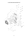
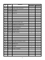
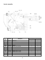
14. EXPLODED VIEWS AND PARTS LIST ........................................................................ 90
–2–
Original instruction
Please read carefully through these instructions that contain important information which complies with the
“Machinery” Directive (Directive 2006/42/EC), and ensure that you understand them.
Generic Denomination: Air Conditioner
Definition of Qualified Installer or Qualified Service Person
The air conditioner must be installed, maintained, repaired and removed by a qualified installer or qualified
service person.
When any of these jobs is to be done, ask a qualified installer or qualified service person to do them for you.
A qualified installer or qualified service person is an agent who has the qualifications and knowledge
described in the table below.
Agent
Qualifications and knowledge which the agent must have
Qualified
installer (∗1)
• The qualified installer is a person who installs, maintains, relocates and removes the air
conditioners made by Toshiba Carrier Corporation.
He or she has been trained to install, maintain, relocate and remove the air conditioners made by
Toshiba Carrier Corporation or, alternatively, he or she has been instructed in such operations by
an individual or individuals who have been trained and is thus thoroughly acquainted with the
knowledge related to these operations.
• The qualified installer who is allowed to do the electrical work involved in installation, relocation
and removal has the qualifications pertaining to this electrical work as stipulated by the local laws
and regulations, and he or she is a person who has been trained in matters relating to electrical
work on the air conditioners made by Toshiba Carrier Corporation or, alternatively, he or she has
been instructed in such matters by an individual or individuals who have been trained and is thus
thoroughly acquainted with the knowledge related to this work.
• The qualified installer who is allowed to do the refrigerant handling and piping work involved in
installation, relocation and removal has the qualifications pertaining to this refrigerant handling
and piping work as stipulated by the local laws and regulations, and he or she is a person who
has been trained in matters relating to refrigerant handling and piping work on the air conditioners
made by Toshiba Carrier Corporation or, alternatively, he or she has been instructed in such
matters by an individual or individuals who have been trained and is thus thoroughly acquainted
with the knowledge related to this work.
• The qualified installer who is allowed to work at heights has been trained in matters relating to
working at heights with the air conditioners made by Toshiba Carrier Corporation or, alternatively,
he or she has been instructed in such matters by an individual or individuals who have been
trained and is thus thoroughly acquainted with the knowledge related to this work.
Qualified service
person (∗1)
• The qualified service person is a person who installs, repairs, maintains, relocates and removes
the air conditioners made by Toshiba Carrier Corporation. He or she has been trained to install,
repair, maintain, relocate and remove the air conditioners made by Toshiba Carrier Corporation or,
alternatively, he or she has been instructed in such operations by an individual or individuals who
have been trained and is thus thoroughly acquainted with the knowledge related to these operations.
• The qualified service person who is allowed to do the electrical work involved in installation,
repair, relocation and removal has the qualifications pertaining to this electrical work as stipulated
by the local laws and regulations, and he or she is a person who has been trained in matters
relating to electrical work on the air conditioners made by Toshiba Carrier Corporation or,
alternatively, he or she has been instructed in such matters by an individual or individuals who
have been trained and is thus thoroughly acquainted with the knowledge related to this work.
• The qualified service person who is allowed to do the refrigerant handling and piping work
involved in installation, repair, relocation and removal has the qualifications pertaining to this
refrigerant handling and piping work as stipulated by the local laws and regulations, and he or
she is a person who has been trained in matters relating to refrigerant handling and piping
work on the air conditioners made by Toshiba Carrier Corporation or, alternatively, he or she
has been instructed in such matters by an individual or individuals who have been trained
and is thus thoroughly acquainted with the knowledge related to this work.
• The qualified service person who is allowed to work at heights has been trained in matters
relating to working at heights with the air conditioners made by Toshiba Carrier Corporation or,
alternatively, he or she has been instructed in such matters by an individual or individuals who
have been trained and is thus thoroughly acquainted with the knowledge related to this work.
–3–
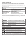
Definition of Protective Gear
When the air conditioner is to be transported, installed, maintained, repaired or removed, wear protective
gloves and ‘safety’ work clothing.
In addition to such normal protective gear, wear the protective gear described below when undertaking the
special work detailed in the table below.
Failure to wear the proper protective gear is dangerous because you will be more susceptible to injury, burns,
electric shocks and other injuries.
Protective gear worn
Work undertaken
All types of work
Protective gloves
“Safety” working clothing
Electrical-related work
Gloves to provide protection for electricians and from heat
Insulating shoes
Clothing to provide protection from electric shock
Work done at heights (50 cm or more)
Helmets for use in industry
Transportation of heavy objects
Shoes with additional protective toe cap
Repair of outdoor unit
Gloves to provide protection for electricians and from heat
The important contents concerned to the safety are described on the product itself and on this Service Manual.
Please read this Service Manual after understanding the described items thoroughly in the following contents
(Indications/Illustrated marks), and keep them.
[Explanation of indications]
Indication
Explanation
DANGER
Indicates contents assumed that an imminent danger causing a death or serious injury of
the repair engineers and the third parties when an incorrect work has been executed.
WARNING
Indicates possibilities assumed that a danger causing a death or serious injury of the
repair engineers, the third parties, and the users due to troubles of the product after work
when an incorrect work has been executed.
CAUTION
Indicates contents assumed that an injury or property damage (∗) may be caused on the
repair engineers, the third parties, and the users due to troubles of the product after work
when an incorrect work has been executed.
∗ Property damage : Enlarged damage concerned to property, furniture, and domestic animal/pet
[Explanation of illustrated marks]
Mark
Explanation
Indicates prohibited items (Forbidden items to do)
The sentences near an illustrated mark describe the concrete prohibited contents.
Indicates mandatory items (Compulsory items to do)
The sentences near an illustrated mark describe the concrete mandatory contents.
Indicates cautions (Including danger/warning)
The sentences or illustration near or in an illustrated mark describe the concrete cautious contents.
–4–
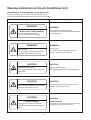
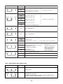
Warning Indications on the Air Conditioner Unit
[Confirmation of warning label on the main unit]
Confirm that labels are indicated on the specified positions
If removing the label during parts replace, stick it as the original.
Description
Warning indication
WARNING
WARNING
ELECTRICAL SHOCK HAZARD
Disconnect all remote electric
power supplies before servicing.
WARNING
ELECTRICAL SHOCK HAZARD
Disconnect all remote electric power supplies
before servicing.
WARNING
Moving parts.
Do not operate unit with grille removed.
Stop the unit before the servicing.
CAUTION
Moving parts.
Do not operate unit with grille removed.
Stop the unit before the servicing.
CAUTION
High temperature parts.
You might get burned when removing
this panel.
CAUTION
High temperature parts.
You might get burned when removing this panel.
CAUTION
Do not touch the aluminum fins of the unit.
Doing so may result in injury.
CAUTION
Do not touch the aluminum fins of the unit.
Doing so may result in injury.
CAUTION
BURST HAZARD
Open the service valves before the
operation, otherwise there might be the
burst.
–5–
BURST HAZARD
Open the service valves before the operation,
otherwise there might be the burst.
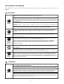
Precaution for Safety
The manufacturer shall not assume any liability for the damage caused by not observing the description of this
manual.
DANGER
Before carrying out the installation, maintenance, repair or removal work, be sure to set the circuit
breaker to the OFF position. Otherwise, electric shocks may result.
Before opening the intake grille of the indoor unit or service panel of the outdoor unit, set the circuit
breaker to the OFF position. Failure to set the circuit breaker to the OFF position may result in electric
shocks through contact with the interior parts. Only a qualified installer (*1) or qualified service person
(*1) is allowed to remove the intake grille of the indoor unit or service panel of the outdoor unit and do
the work required.
Turn off
breaker.
Before starting to repair the outdoor unit fan or fan guard, be absolutely sure to set the circuit breaker
to the OFF position, and place a “Work in progress” sign on the circuit breaker before proceeding with
the work.
When cleaning the filter or other parts of the indoor unit, set the circuit breaker to OFF without fail, and
place a “Work in progress” sign near the circuit breaker before proceeding with the work.
When you access inside of the service panel to repair electric parts, wait for about five minutes after
turning off the breaker. Do not start repairing immediately. Otherwise you may get electric shock by
touching terminals of high-voltage capacitors. Natural discharge of the capacitor takes about five
minutes.
Electric shock
hazard
Execute
discharge
between
terminals.
Before operating the air conditioner after having completed the work, check that the electrical parts
box cover of the indoor unit and service panel of the outdoor unit are closed, and set the circuit
breaker to the ON position. You may receive an electric shock etc. if the power is turned on without first
conducting these checks.
Even if the circuit breaker has been set to the OFF position before the service panel is removed and
the electrical parts are repaired, you will still risk receiving an electric shock.
For this reason, short-circuit the high-voltage capacitor terminals to discharge the voltage before
proceeding with the repair work. For details on the short-circuiting procedure, refer to the Service
Manual. You may receive an electric shock if the voltage stored in the capacitors has not been
sufficiently discharged.
Place a “Work in progress” sign near the circuit breaker while the installation, maintenance, repair or
removal work is being carried out. There is a danger of electric shocks if the circuit breaker is set to
ON by mistake.
Prohibition
Stay on
protection
When checking the electric parts, removing the cover of the electric parts box of Indoor Unit and/or
front panel of Outdoor Unit inevitably to determine the failure, put a sign “Do not enter” around the site
before the work. Failure to do this may result in third person getting electric shock.
If, in the course of carrying out repairs, it becomes absolutely necessary to check out the electrical
parts with the electrical parts box cover of one or more of the indoor units and the service panel of the
outdoor unit removed in order to find out exactly where the trouble lies, wear insulated heat-resistant
gloves, insulated boots and insulated work overalls, and take care to avoid touching any live parts.
You may receive an electric shock if you fail to heed this warning. Only qualified service person (*1) is
allowed to do this kind of work.
WARNING
Before starting to repair the air conditioner, read carefully through the Service Manual, and repair the
air conditioner by following its instructions.
Only qualified service person (*1) is allowed to repair the air conditioner. Repair of the air conditioner
by unqualified person may give rise to a fire, electric shocks, injury, water leaks and/or other problems.
Only a qualified installer (*1) or qualified service person (*1) is allowed to carry out the electrical work
of the air conditioner. Under no circumstances must this work be done by an unqualified individual
since failure to carry out the work properly may result in electric shocks and/or electrical leaks.
General
Wear protective gloves and safety work clothing during installation, servicing and removal.
Use wiring that meets the specifications in the Installation Manual and the stipulations in the local
regulations and laws. Use of wiring which does not meet the specifications may give rise to electric
shocks, electrical leakage, smoking and/or a fire.
–6–
WARNING
The appliance shall be installed in accordance with national wiring regulations. Capacity shortages of
the power circuit or an incomplete installation may cause an electric shock or fire.
Only a qualified installer (*1) or qualified service person (*1) is allowed to undertake work at heights
using a stand of 50 cm or more or to remove the intake grille of the indoor unit to undertake work.
When working at heights, use a ladder which complies with the ISO 14122 standard, and follow the
procedure in the ladder’s instructions. Also wear a helmet for use in industry as protective gear to
undertake the work.
When working at heights, put a sign in place so that no-one will approach the work location, before
proceeding with the work. Parts and other objects may fall from above, possibly injuring a person
below.
General
Do not touch the aluminum fin of the outdoor unit. You may injure yourself if you do so. If the fin must
be touched for some reason, first put on protective gloves and safety work clothing, and then proceed.
Use forklift to carry in the air conditioner units and use winch or hoist at installation of them.
Do not climb onto or place objects on top of the outdoor unit. You may fall or the objects may fall off of
the outdoor unit and result in injury.
When transporting the air conditioner, wear shoes with additional protective toe caps.
When transporting the air conditioner, do not take hold of the bands around the packing carton.
You may injure yourself if the bands should break.
When transporting the air conditioner, use a forklift and when moving the air conditioner by hand,move
the unit with 4 people.
Do not customize the product. Doing so may result in electric shock or other failure.
This air conditioner has passed the pressure test as specified in IEC 60335-2-40 Annex EE.
Before troubleshooting or repair work, check the earth wire is connected to the earth terminals of the
main unit, otherwise an electric shock is caused when a leak occurs.If the earth wire is not correctly
connected, contact an electric engineer for rework.
Check earth
wires.
Prohibition of
modification.
Use specified
parts.
Do not bring a
child close to
the equipment.
Insulating
measures
No fire
After completing the repair or relocation work, check that the ground wires are connected properly.
Be sure to connect earth wire. (Grounding work) Incomplete grounding causes an electric shock.
Do not connect ground wires to gas pipes, water pipes, and lightning rods or ground wires for
telephone wires.
Do not modify the products.Do not also disassemble or modify the parts. It may cause a fire, electric
shock or injury.
When any of the electrical parts are to be replaced, ensure that the replacement parts satisfy the
specifications given in the Service Manual (or use the parts contained on the parts list in the Service
Manual). Use of any parts which do not satisfy the required specifications may give rise to electric
shocks, smoking and/or a fire.
If, in the course of carrying out repairs, it becomes absolutely necessary to check out the electrical
parts with the electrical parts box cover of one or more of the indoor units and the service panel of the
outdoor unit removed in order to find out exactly where the trouble lies, place "Keep out" signs around
the work site before proceeding. Third-party individuals may enter the work site and receive electric
shocks if this warning is not heeded.
Connect the cut-off lead wires with crimp contact, etc, put the closed end side upward and then apply
a water-cut method, otherwise a leak or production of fire is caused at the users’ side.
When performing repairs using a gas burner, replace the refrigerant with nitrogen gas because the oil
that coats the pipes may otherwise burn. When repairing the refrigerating cycle, take the following
measures.
1) Be attentive to fire around the cycle.
When using a gas stove, etc, be sure to put out fire before work; otherwise the oil mixed with
refrigerant gas may catch fire.
2) Do not use a welder in the closed room. When using it without ventilation, carbon monoxide
poisoning may be caused.
3) Do not bring inflammables close to the refrigerant cycle, otherwise fire of the welder may catch the
inflammables.
–7–
The refrigerant used by this air conditioner is the R410A.
Check the used refrigerant name and use tools and materials of the parts which match with it.
For the products which use R410A refrigerant, the refrigerant name is indicated at a position on the
outdoor unit where is easy to see. To prevent miss-charging, the route of the service port is changed
from one of the former R22.
Do not use any refrigerant different from the one specified for complement or replacement.
Otherwise, abnormally high pressure may be generated in the refrigeration cycle, which may result in a
failure or explosion of the product or an injury to your body.
For an air conditioner which uses R410A, never use other refrigerant than R410A.
For an air conditioner which uses other refrigerant (R22, etc.), never use R410A.
If different types of refrigerant are mixed, abnormal high pressure generates in the refrigerating cycle
and an injury due to breakage may be caused.
Refrigerant
Do not charge refrigerant additionally. If charging refrigerant additionally when refrigerant gas leaks,
the refrigerant composition in the refrigerating cycle changes resulted in change of air conditioner
characteristics or refrigerant over the specified standard amount is charged and an abnormal high
pressure is applied to the inside of the refrigerating cycle resulted in cause of breakage or injury.
Therefore if the refrigerant gas leaks, recover the refrigerant in the air conditioner, execute vacuuming,
and then newly recharge the specified amount of liquid refrigerant. In this time, never charge the
refrigerant over the specified amount.
When recharging the refrigerant in the refrigerating cycle, do not mix the refrigerant or air other than
R410A into the specified refrigerant. If air or others is mixed with the refrigerant, abnormal high
pressure generates in the refrigerating cycle resulted in cause of injury due to breakage.
After installation work, check the refrigerant gas does not leak. If the refrigerant gas leaks in the room,
poisonous gas generates when gas touches to fire such as fan heater, stove or cocking stove though
the refrigerant gas itself is innocuous.
Never recover the refrigerant into the outdoor unit. When the equipment is moved or repaired, be sure
to recover the refrigerant with recovering device. The refrigerant cannot be recovered in the outdoor
unit; otherwise a serious accident such as breakage or injury is caused.
Assembly/
Cabling
Insulator check
After repair work, surely assemble the disassembled parts, and connect and lead the removed wires
as before. Perform the work so that the cabinet or panel does not catch the inner wires. If incorrect
assembly or incorrect wire connection was done, a disaster such as a leak or fire is caused at user’s
side.
After the work has finished, be sure to use an insulation tester set (500V Megger) to check the
resistance is 1MΩ or more between the charge section and the non-charge metal section
(Earth position). If the resistance value is low, a disaster such as a leak or electric shock is caused at
user’s side.
When the refrigerant gas leaks during work, execute ventilation. If the refrigerant gas touches to a fire,
poisonous gas generates. A case of leakage of the refrigerant and the closed room full with gas is
dangerous because a shortage of oxygen occurs. Be sure to execute ventilation.
Ventilation
If refrigerant gas has leaked during the installation work, ventilate the room immediately.
If the leaked refrigerant gas comes in contact with fire, noxious gas may be generated.
After the installation or servicing work, confirm that refrigerant gas does not leak. If refrigerant gas
leaks into the room and flows near a fire source, such as a cooking range, noxious gas may be
generated.
When the refrigerant gas leaks, find up the leaked position and repair it surely. If the leaked position
cannot be found up and the repair work is interrupted, pump-down and tighten the service valve,
otherwise the refrigerant gas may leak into the room. The poisonous gas generates when gas touches
to fire such as fan heater, stove or cocking stove though the refrigerant gas itself is innocuous. When
installing equipment which includes a large amount of charged refrigerant such as a multi air
conditioner in a sub-room, it is necessary that the density does not the limit even if the refrigerant
leaks. If the refrigerant leaks and exceeds the limit density, an accident of shortage of oxygen is
caused.
Compulsion
Tighten the flare nut with a torque wrench in the specified manner. Excessive tighten of the flare nut
may cause a crack in the flare nut after a long period, which may result in refrigerant leakage.
Nitrogen gas must be used for the airtight test.
The charge hose must be connected in such a way that it is not slack.
For the installation/moving/reinstallation work, follow to the Installation Manual. If an incorrect
installation is done, a trouble of the refrigerating cycle, water leak, electric shock or fire is caused.
–8–
Once the repair work has been completed, check for refrigerant leaks, and check the insulation
resistance and water drainage. Then perform a trial run to check that the air conditioner is running
properly.
Check after
repair
After repair work has finished, check there is no trouble. If check is not executed, a fire, electric shock
or injury may be caused. For a check, turn off the power breaker.
After repair work (installation of front panel and cabinet) has finished, execute a test run to check there
is no generation of smoke or abnormal sound. If check is not executed, a fire or an electric shock is
caused. Before test run, install the front panel and cabinet.
Check the following matters before a test run after repairing piping.
• Connect the pipes surely and there is no leak of refrigerant.
• The valve is opened.
Running the compressor under condition that the valve closes causes an abnormal high pressure
Do not
resulted in damage of the parts of the compressor and etc. and moreover if there is leak of
operate the unit
refrigerant at connecting section of pipes, the air is suctioned and causes further abnormal high
with the valve
pressure resulted in burst or injury.
closed.
Only a qualified installer (*1) or qualified service person (*1) is allowed to relocate the air conditioner. It
is dangerous for the air conditioner to be relocated by an unqualified individual since a fire, electric
shocks, injury, water leakage, noise and/or vibration may result.
Check after
reinstallation
Check the following items after reinstallation.
1) The earth wire is correctly connected.
2) The power cord is not caught in the product.
3) There is no inclination or unsteadiness and the installation is stable.
If check is not executed, a fire, an electric shock or an injury is caused.
When carrying out the pump-down work shut down the compressor before disconnecting the
refrigerant pipe. Disconnecting the refrigerant pipe with the service valve left open and the compressor
still operating will cause air, etc. to be sucked in, raising the pressure inside the refrigeration cycle to
an abnormally high level, and possibly resulting in reputing, injury, etc.
When the service panel of the outdoor unit is to be opened in order for the compressor or the area
around this part to be repaired immediately after the air conditioner has been shut down, set the circuit
breaker to the OFF position, and then wait at least 10 minutes before opening the service panel. If you
fail to heed this warning, you will run the risk of burning yourself because the compressor pipes and
other parts will be very hot to the touch. In addition, before proceeding with the repair work, wear the
heat-resistant gloves.
Cooling check
When the service panel of the outdoor unit is to be opened in order for the fan motor, reactor, inverter
or the areas around these parts to be repaired immediately after the air conditioner has been shut
down, set the circuit breaker to the OFF position, and then wait at least 10 minutes before opening the
service panel. If you fail to heed this warning, you will run the risk of burning yourself because the fan
motor, reactor, inverter heat sink and other parts will be very hot to the touch.
In addition, before proceeding with the repair work, wear the heat-resistant gloves.
Only a qualified installer (*1) or qualified service person (*1) is allowed to install the air conditioner. If
the air conditioner is installed by an unqualified individual, a fire, electric shocks, injury, water leakage,
noise and/or vibration may result.
Before starting to install the air conditioner, read carefully through the Installation Manual, and follow
its instructions to install the air conditioner.
Do not install the air conditioner in a location that may be subject to a risk of expire to a combustible
gas. If a combustible gas leaks and becomes concentrated around the unit, a fire may occur.
Installation
Install the indoor unit at least 2.5 m above the floor level since otherwise the users may injure
themselves or receive electric shocks if they poke their fingers or other objects into the indoor unit
while the air conditioner is running.
Install a circuit breaker that meets the specifications in the installation manual and the stipulations in
the local regulations and laws.
Install the circuit breaker where it can be easily accessed by the agent.
Do not place any combustion appliance in a place where it is directly exposed to the wind of air
conditioner, otherwise it may cause imperfect combustion.
–9–
Explanations given to user
• If you have discovered that the fan grille is damaged, do not approach the outdoor unit but set the circuit breaker
to the OFF position, and contact a qualified service person to have the repairs done.
Do not set the circuit breaker to the ON position until the repairs are completed.
Relocation
• Only a qualified installer (∗1) or qualified service person (∗1) is allowed to relocate the air conditioner.
It is dangerous for the air conditioner to be relocated by an unqualified individual since a fire, electric shocks,
injury, water leakage, noise and/or vibration may result.
• When carrying out the pump-down work shut down the compressor before disconnecting the refrigerant pipe.
Disconnecting the refrigerant pipe with the service valve left open and the compressor still operating will cause air,
etc. to be sucked in, raising the pressure inside the refrigeration cycle to an abnormally high level, and possibly
resulting in reputing, injury, etc.
(∗1) Refer to the “Definition of Qualified Installer or Qualified Service Person.”
Declaration of Conformity
Manufacturer:
Toshiba Carrier Corporation
336 Tadehara, Fuji-shi, Shizuoka-ken 416-8521 JAPAN
Authorized
Nick Ball
Representative/TCF holder:
Toshiba EMEA Engineering Director
Toshiba Carrier UK Ltd.
Porsham Close, Belliver Industrial Estate,
PLYMOUTH, Devon, PL6 7DB.
United Kingdom
Hereby declares that the machinery described below:
Generic Denomination:
Air Conditioner
Model/type:
RAV-SM1103AT-E1
RAV-SM1403AT-E1
Commercial name:
Digital Inverter Series Air Conditioner
Complies with the provisions of the “Machinery” Directive (Directive 2006/42/EC) and the regulations transposing
into national law.
Complies with the provisions of the following harmonized standard:
EN 378-2: 2008 + A1:2009
Note: This declaration becomes invalid if technical or operational modifications are introduced without the
manufacturer’s consent.
Disposal
How to dispose of air conditioners with a rating of 12 kW and below in accordance with the 2002/96/EC Directive
WEEE (Waste Electrical and Electronic Equipment) is provided in the Installation Manual supplied with your product.
For disposal of the product above 12 kW in rating you should use a registered company in accordance with any
national or EU legislation.
<Model names with a rating of 12 kW and below (outdoor units)>
DI series
RAV-SM563AT-E
RAV-SM803AT-E
RAV-SM1103AT-E, RAV-SM1103AT-E1
RAV-SP404ATZ-E
RAV-SP454ATZ-E
RAV-SP564ATZ-E
RAV-SP804ATZ-E
RAV-SP1104ATZ-E
RAV-SP1104AT8Z-E
RAV-SP1104AT8Z-TR
RAV-SP404ATZG-E
RAV-SP454ATZG-E
RAV-SP564ATZG-E
RAV-SP804ATZG-E
RAV-SP1104ATZG-E
RAV-SP1104AT8ZG-E
RAV-SP1104AT8ZG-TR
SDI series
RAV-SP404AT-E
RAV-SP454AT-E
RAV-SP564AT-E
RAV-SP804AT-E
RAV-SP1104AT-E
RAV-SP1104AT8-E
RAV-SP1104AT8-TR
– 10 –
New Refrigerant (R410A)
This air conditioner adopts a new HFC type refrigerant (R410A) which does not deplete the ozone layer.
1. Safety Caution Concerned to New Refrigerant
The pressure of R410A is high 1.6 times of that of the former refrigerant (R22).
Accompanied with change of refrigerant, the refrigerating oil has been also changed.
Therefore, be sure that water, dust, the former refrigerant or the former refrigerating oil is not mixed into the
refrigerating cycle of the air conditioner with new refrigerant during installation work or service work.
If an incorrect work or incorrect service is performed, there is a possibility to cause a serious accident.
Use the tools and materials exclusive to R410A to purpose a safe work.
2. Cautions on Installation/Service
1) Do not mix the other refrigerant or refrigerating oil.
For the tools exclusive to R410A, shapes of all the joints including the service port differ from those of
the former refrigerant in order to prevent mixture of them.
2) As the use pressure of the new refrigerant is high, use material thickness of the pipe and tools which are
specified for R410A.
3) In the installation time, use clean pipe materials and work with great attention so that water and others
do not mix in because pipes are affected by impurities such as water, oxide scales, oil, etc.
Use the clean pipes.
Be sure to brazing with flowing nitrogen gas. (Never use gas other than nitrogen gas.)
4) For the earth protection, use a vacuum pump for air purge.
5) R410A refrigerant is azeotropic mixture type refrigerant.
Therefore use liquid type to charge the refrigerant. (If using gas for charging, composition of the
refrigerant changes and then characteristics of the air conditioner change.)
3. Pipe Materials
For the refrigerant pipes, copper pipe and joints are mainly used.
It is necessary to select the most appropriate pipes to conform to the standard.
Use clean material in which impurities adhere inside of pipe or joint to a minimum.
1) Copper pipe
<Piping>
The pipe thickness, flare finishing size, flare nut and others differ according to a refrigerant type.
When using a long copper pipe for R410A, it is recommended to select “Copper or copper-base pipe
without seam” and one with bonded oil amount 40mg/10m or less.
Also do not use crushed, deformed, discolored (especially inside) pipes.
(Impurities cause clogging of expansion valves and capillary tubes.)
<Flare nut>
Use the flare nuts which are attached to the air conditioner unit.
2) Joint
The flare joint and socket joint are used for joints of the copper pipe.
The joints are rarely used for installation of the air conditioner.
However clear impurities when using them.
– 11 –
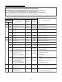
4. Tools
1. Required Tools for R410A
Mixing of different types of oil may cause a trouble such as generation of sludge, clogging of capillary,
etc. Accordingly, the tools to be used are classified into the following three types.
1) Tools exclusive for R410A (Those which cannot be used for conventional refrigerant (R22))
2) Tools exclusive for R410A, but can be also used for conventional refrigerant (R22)
3) Tools commonly used for R410A and for conventional refrigerant (R22)
The table below shows the tools exclusive for R410A and their interchangeability.
Tools exclusive for R410A (The following tools for R410A are required.)
Tools whose specifications are changed for R410A and their interchangeability
R410A
air conditioner installation
No.
Used tool
Usage
Conventional air
conditioner installation
Existence of
new equipment
for R410A
Whether conventional
equipment can be used
Whether
conventional equipment
can be used
c
Flare tool
Pipe flaring
Yes
∗ (Note)
Yes
d
Copper pipe gauge
for adjusting
projection margin
Flaring by
conventional flare tool
Yes
∗ (Note)
∗ (Note)
e
Torque wrench
Tightening of flare nut
Yes
No
No
f
Gauge manifold
g
Charge hose
Evacuating, refrigerant
charge, run check, etc.
Yes
No
No
h
Vacuum pump adapter
Vacuum evacuating
Yes
No
Yes
i
Electronic balance for
refrigerant charging
Refrigerant charge
Yes
Yes
Yes
j
Refrigerant cylinder
Refrigerant charge
Yes
No
No
k
Leakage detector
Gas leakage check
Yes
No
Yes
(Note) When flaring is carried out for R410A using the conventional flare tools, adjustment of projection
margin is necessary. For this adjustment, a copper pipe gauge, etc. are necessary.
General tools (Conventional tools can be used.)
In addition to the above exclusive tools, the following equipments which serve also for R22 are necessary
as the general tools.
1) Vacuum pump. Use vacuum pump by
attaching vacuum pump adapter.
7) Screwdriver (+, –)
2) Torque wrench
8) Spanner or Monkey wrench
3) Pipe cutter
9) Hole core drill
4) Reamer
10) Hexagon wrench (Opposite side 4mm)
5) Pipe bender
11) Tape measure
6) Level vial
12) Metal saw
Also prepare the following equipments for other installation method and run check.
1) Clamp meter
3) Insulation resistance tester (Megger)
2) Thermometer
4) Electroscope
– 12 –
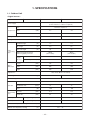
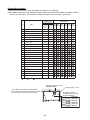
1. SPECIFICATIONS
1-1. Outdoor Unit
<Digital Inverter>
Model name
Outdoor unit
RAV-
SM1103AT-E1
1 phase 230V (220 – 240V) 50Hz
(Power exclusive to outdoor is required.)
Power supply
Type
Hermetic compressor
Compressor Motor
(kW)
Pole
Refrigerant charged
(kg)
2.5
3.0
4
4
2.8
2.8
Refrigerant control
Inter
connecting
pipe
Pulse motor valve
Standard length
(m)
7.5
7.5
Min. length
(m)
5.0
5.0
Max. total length
(m)
50
50
40g/m
(31m to 50m)
40g/m
(31m to 50m)
Additional refrigerant charge
under long piping connector
Outdoor lower
(m)
30
30
Outdoor higher
(m)
30
30
Height
(mm)
795
795
Width
(mm)
900
900
Depth
(mm)
320
320
Height
difference
Outer
dimension
Appearance
Silky shade (Muncel 1Y 8.5/0.5)
Total weight
(kg)
76
Heat exchanger
Propeller fan
Standard air flow
75
75
(W)
100
100
Gas side
(mm)
15.9
15.9
Liquid side
(mm)
9.5
9.5
Motor
Connecting
pipe
76
Finned tube
Fan
Fan unit
SM1403AT-E1
(m³/h.)
Sound pressure level
Cooling/Heating
(dB•A)
53 / 54
54 / 54
Sound power level
Cooling/Heating
(dB•A)
70 / 71
70 / 71
Outside air temperature, Cooling
(˚C)
43 to – 15
Outside air temperature, Heating
(˚C)
15 to – 15
– 13 –
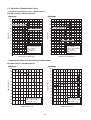
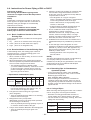
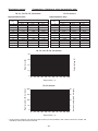
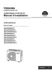
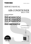
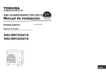
1-2. Operation Characteristic Curve
• Operation Characteristic Curve <Digital Inverter>
RAV-SM1103AT-E1,RAV-SM1403AT-E1
<Cooling>
<Heating>
22
22
20
20
RAV-SM1103AT-E
RAV-SM1103AT-E1
18
18
16
14
Current (A)
Current (A)
14
12
10
12
10
8
8
6
6
• Conditions
Indoor : DB27˚C/WB19˚C
Outdoor : DB35˚C
Air flow : High
Pipe length : 7.5m
230V
4
2
0
RAV-SM1403AT-E1
RAV-SM1403AT-E
16
RAV-SM1403AT-E
RAV-SM1403AT-E1
0
20
40
60
80
100
RAV-SM1103AT-E
RAV-SM1103AT-E1
• Conditions
Indoor : DB20˚C
Outdoor : DB7˚C/WB6˚C
Air flow : High
Pipe length : 7.5m
230V
4
2
0
120
0
20
Compressor speed (rps)
40
60
80
100
120
Compressor speed (rps)
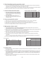
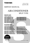
• Capacity variation ratio according to temperature
RAV-SM1103AT-E1,RAVSM1403AT-E1
<Cooling>
<Heating>
105
120
100
110
95
100
90
Capacity ratio (%)
Capacity ratio (%)
90
85
80
75
70
65
60
55
80
70
60
50
40
30
20
• Conditions
Indoor : DB27˚C/WB19˚C
Indoor air flow : High
Pipe length : 7.5m
• Conditions
Indoor : DB20˚C
Indoor air flow : High
Pipe length : 7.5m
10
50
32 33 34 35 36 37 38 39 40 41 42 43
0
Outdoor temp. (˚C)
-14 -12 -10 -8 -6 -4 -2
0
2
Outdoor temp. (˚C)
– 14 –
4
6
8 10
Revision 1 : Mar. 2012
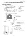
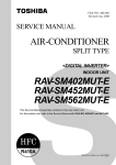
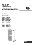
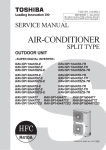
2 . CONSTRUCTION VIEWS (EXTERNAL VIEWS)
RAV-SM1103AT-E1, RAV-SM1403AT-E1
– 15 –
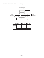
RBC-TWP30E2, RBC-TWP50E2 (Simultaneous Twin)
B
Inner diameter Ø C
Inner
diameter Ø D
Inner
diameter Ø D
A
A
B
C
D
Liquid side
36
14
Ø9.5
Ø6.4
Gas side
43
23
Ø15.9
Ø12.7
Liquid side
34
14
Ø9.5
Ø9.5
Gas side
44
21
Ø15.9
Ø15.9
Model (RBC-)
TWP30E2
TWP50E2
– 16 –
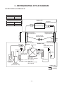
3 . REFRIGERATING CYCLE DIAGRAM
RAV-SM1103AT-E1, RAV-SM1403AT-E1
Outer diameter of refrigerant pipe
Gas side ØA
Liquid side ØB
15.9mm
9.5mm
Indoor unit
Height difference (m)
Outdoor unit
at upper side
Outdoor unit
at lower side
30
30
Distributor
(Strainer incorporated)
TCJ sensor
Strainer
Air heat exchanger
TC sensor
Height difference
Refrigerant pipe
at gas side Ø15.9
Refrigerant pipe
at liquid side Ø9.5
Section shape
of heat insulator
Min.
5m
TS sensor
Ball valve
Outer dia. ØA
Strainer TO sensor
Pressure
switch
P
TD sensor
Outdoor unit
Max.
50m
Packed valve
Outer dia. ØB
PMV
(Pulse Motor Valve)
(UKV-25D22)
TL sensor
Strainer
4-way valve
(STF-H0218)
Muffler
Accumulator
(2500cc)
Rotary
compressor
(DA422A3F-12M)
TE
sensor
Heat exchanger
Outer side
Ø8, 2 rows, 20 steps
Ø25 × L210 FP1.3 flat fin
Inner side
Ø25 × L180
Ø9.52 row, 30 steps
FP1.5 flat fin
Distributor
R410A 2.8kg
Cooling
Heating
– 17 –
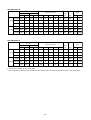
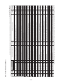
RAV-SM1103AT-E1
Pressure
*Comp.
Pipe surface temp.
(kg/cm2G)
(MPa)
Temp
Pd
Ps
Pd
Ps
TD
TS
TC
TL
TE
Hz
Fan
In
Out
Standard
3.44
0.92
35.1
9.4
82
8
10
56
39
47
HIGH
27/19
35/–
Cooling Overload
3.73
1.18
38.1
12.0
82
15
17
59
48
42
HIGH
32/24
43/–
Low load
1.49
0.70
15.2
7.1
39
8
3
23
22
30
LOW 18/15.5 –5/–
Standard
2.80
0.61
28.6
6.2
80
0
46
7
1
48
HIGH
20/–
7/6
Heating Overload
3.43
1.08
35.0
11.0
82
14
55
12
13
24
LOW
30/–
24/18
Low load
2.20
0.25
22.4
2.6
76
-19
36
-16
-16
55
HIGH
15/– –10/(70%)
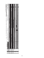
RAV-SM1403AT-E1
Pressure
(MPa)
*Comp.
Pipe surface temp.
(kg/cm2G)
Temp
Pd
Ps
Pd
Ps
TD
TS
TC
TL
TE
Hz
Fan
In
Out
Standard
3.52
0.85
35.9
8.7
87
8
9
57
39
54
HIGH
27/19
35/–
Cooling Overload
3.78
1.12
38.6
11.4
84
15
17
59
47
45
HIGH
32/24
43/–
Low load
1.51
0.71
15.4
7.2
40
7
3
23
23
30
LOW 18/15.5 –5/–
Standard
2.88
0.60
29.4
6.1
85
1
47
6
1
61
HIGH
20/–
7/6
Heating Overload
3.41
1.08
34.8
11.0
81
14
54
13
13
24
LOW
30/–
24/18
Low load
2.35
0.24
24.0
2.4
80
-19
40
-16
-16
73
HIGH
15/– –10/(70%)
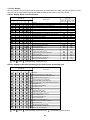
* 4 poles are provided to this compressor.
The compressor frequency (Hz) measured with a clamp meter is 2 times of revolutions (rps) of the compressor.
– 18 –
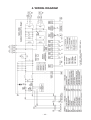
4. WIRING DIAGRAM
– 19 –
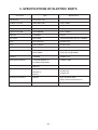
5. SPECIFICATIONS OF ELECTRIC PARTS
Part name
Type
Specifications
Compressor
DA422A3F-12M
Outdoor fan motor
WDF-340-A100-1
Output 100W
Reactor
CH62-2Z-T
6mH, 18.5A
4-way valve coil
STF-H01AJ1949A1
AC230V
High-pressure SW
ACB-4UB83W
OFF: 4.15MPa
PMV coil
UKV-A039
DC12V
P.C. board
MCC-1630
1Ø AC220V/230V/240V±10%, 50/60HZ
Fuse
GDT 250V25A
AC250V, 25A
Fuse
50T (P) 063HF
AC250V, 6.3A
Fuse
SCT3.15A
AC250V, 3.15A
Surge absorber
DA38-362MT or
DA38-302MT
Discharge voltage 3600V
Discharge voltage 3000V
Rectifier
D25XB60
DC600V, 25A
Electrolytic condenser
LLQ2G761KHUATF or
ECST401LIN761KA58
DC400V, 760μF
Power relay
DW12D1
AC250V, 20A x 2
Relay
G5NB or
DQ12D1 or
RPG-12
AC250V, 3A
AC250V, 5A
AC250V, 3A
Switching transformer
SWT-91
Input: DC240 to 390V
Output: DC7V, DC13V, DC17V
Fuse
50T100H
AC250V, 10A
– 20 –
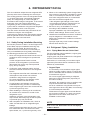
6. REFRIGERANT R410A
This air conditioner adopts the new refrigerant HFC
(R410A) which does not damage the ozone layer.
The working pressure of the new refrigerant R410A
is 1.6 times higher than conventional refrigerant
(R22). The refrigerating oil is also changed in
accordance with change of refrigerant, so be careful
that water, dust, and existing refrigerant or
refrigerating oil are not entered in the refrigerant
cycle of the air conditioner using the new refrigerant
during installation work or servicing time.
The next section describes the precautions for air
conditioner using the new refrigerant.
Conforming to contents of the next section together
with the general cautions included in this manual,
perform the correct and safe work.
6-1. Safety During Installation/Servicing
As R410A’s pressure is about 1.6 times higher than
that of R22, improper installation/servicing may
cause a serious trouble. By using tools and
materials exclusive for R410A, it is necessary to
carry out installation/servicing safely while taking
the following precautions into consideration.
1. Never use refrigerant other than R410A in an air
conditioner which is designed to operate with
R410A.
If other refrigerant than R410A is mixed,
pressure in the refrigeration cycle becomes
abnormally high, and it may cause personal
injury, etc. by a rupture.
2. Confirm the used refrigerant name, and use
tools and materials exclusive for the refrigerant
R410A.
The refrigerant name R410A is indicated on the
visible place of the outdoor unit of the air
conditioner using R410A as refrigerant.
To prevent mischarging, the diameter of the
service port differs from that of R22.
3. If a refrigeration gas leakage occurs during
installation/servicing, be sure to ventilate fully.
If the refrigerant gas comes into contact with fire,
a poisonous gas may occur.
4. When installing or removing an air conditioner,
do not allow air or moisture to remain in the
refrigeration cycle.
Otherwise, pressure in the refrigeration cycle
may become abnormally high so that a rupture
or personal injury may be caused.
5. After completion of installation work, check to
make sure that there is no refrigeration gas
leakage.
If the refrigerant gas leaks into the room, coming
into contact with fire in the fan-driven heater,
space heater, etc., a poisonous gas may occur.
6. When an air conditioning system charged with a
large volume of refrigerant is installed in a small
room, it is necessary to exercise care so that,
even when refrigerant leaks, its concentration
does not exceed the marginal level.
If the refrigerant gas leakage occurs and its
concentration exceeds the marginal level, an
oxygen starvation accident may result.
7. Be sure to carry out installation or removal
according to the installation manual.
Improper installation may cause refrigeration
trouble, water leakage, electric shock, fire, etc.
8. Unauthorized modifications to the air conditioner
may be dangerous. If a breakdown occurs
please call a qualified air conditioner technician
or electrician.
Improper repair may result in water leakage,
electric shock and fire, etc.
6-2. Refrigerant Piping Installation
6-2-1. Piping Materials and Joints Used
For the refrigerant piping installation, copper pipes
and joints are mainly used.
Copper pipes and joints suitable for the refrigerant
must be chosen and installed.
Furthermore, it is necessary to use clean copper
pipes and joints whose interior surfaces are less
affected by contaminants.
1. Copper Pipes
It is necessary to use seamless copper pipes
which are made of either copper or copper alloy
and it is desirable that the amount of residual oil
is less than 40 mg/10 m.
Do not use copper pipes having a collapsed,
deformed or discolored portion (especially on
the interior surface).
Otherwise, the expansion valve or capillary tube
may become blocked with contaminants.
As an air conditioner using R410A incurs pressure higher than when using R22, it is necessary
to choose adequate materials.
Thicknesses of copper pipes used with R410A
are as shown in Table 6-2-1. Never use copper
pipes thinner than 0.8mm even when it is
available on the market.
NOTE
Refer to the “6-6. Instructions for Re-use Piping
of R22 or R407C”.
– 21 –
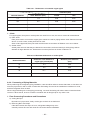
Table 6-2-1 Thicknesses of annealed copper pipes
Thickness (mm)
Nominal diameter
Outer diameter (mm)
R410A
R22
1/4
6.4
0.80
0.80
3/8
9.5
0.80
0.80
1/2
12.7
0.80
0.80
5/8
15.9
1.00
1.00
1. Joints
For copper pipes, flare joints or socket joints are used. Prior to use, be sure to remove all contaminants.
a) Flare Joints
Flare joints used to connect the copper pipes cannot be used for pipings whose outer diameter exceeds
20 mm. In such a case, socket joints can be used.
Sizes of flare pipe ends, flare joint ends and flare nuts are as shown in Tables 6-2-3 to 6-2-5 below.
b) Socket Joints
Socket joints are such that they are brazed for connections, and used mainly for thick pipings whose
diameter is larger than 20 mm. Thicknesses of socket joints are as shown in Table 6-2-2.
Table 6-2-2 Minimum thicknesses of socket joints
Nominal diameter
Reference outer diameter of
copper pipe jointed (mm)
Minimum joint thickness
(mm)
1/4
6.4
0.50
3/8
9.5
0.60
1/2
12.7
0.70
5/8
15.9
0.80
6-2-2. Processing of Piping Materials
When performing the refrigerant piping installation, care should be taken to ensure that water or dust does not
enter the pipe interior, that no other oil other than lubricating oils used in the installed air conditioner is used,
and that refrigerant does not leak.
When using lubricating oils in the piping processing, use such lubricating oils whose water content has been
removed. When stored, be sure to seal the container with an airtight cap or any other cover.
1. Flare Processing Procedures and Precautions
a) Cutting the Pipe
By means of a pipe cutter, slowly cut the pipe so that it is not deformed.
b) Removing Burrs and Chips
If the flared section has chips or burrs, refrigerant leakage may occur.
Carefully remove all burrs and clean the cut surface before installation.
– 22 –
c) Insertion of Flare Nut
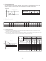
d) Flare Processing
Make certain that a clamp bar and copper pipe have been cleaned.
By means of the clamp bar, perform the flare processing correctly.
Use either a flare tool for R410A or conventional flare tool.
Flare processing dimensions differ according
to the type of flare tool.
When using a conventional flare tool, be sure
to secure “dimension A” by using a gauge for
size adjustment.
ØD
A
Fig. 6-2-1 Flare processing dimensions
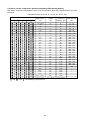
Table 6-2-3 Dimensions related to flare processing for R410A / R22
A (mm)
Nominal
diameter
Outer
diameter
(mm)
Thickness
(mm)
Flare tool for
R410A, R22
clutch type
Conventional flare tool
(R410A)
Conventional flare tool
(R22)
Clutch type
Wing nut type
Clutch type
Wing nut type
1/4
6.4
0.8
0 to 0.5
1.0 to 1.5
1.5 to 2.0
0.5 to 1.0
1.0 to 1.5
3/8
9.5
0.8
0 to 0.5
1.0 to 1.5
1.5 to 2.0
0.5 to 1.0
1.0 to 1.5
1/2
12.7
0.8
0 to 0.5
1.0 to 1.5
2.0 to 2.5
0.5 to 1.0
1.5 to 2.0
5/8
15.9
1.0
0 to 0.5
1.0 to 1.5
2.0 to 2.5
0.5 to 1.0
1.5 to 2.0
3/4
19.1
1.2
0 to 0.5
1.0 to 1.5
2.0 to 2.5
—
—
Table 6-2-4 Flare and flare nut dimensions for R410A
Nominal
diameter
Outer diameter
(mm)
Thickness
(mm)
1/4
6.4
3/8
Dimension (mm)
Flare nut width
(mm)
A
B
C
D
0.8
9.1
9.2
6.5
13
17
9.5
0.8
13.2
13.5
9.7
20
22
1/2
12.7
0.8
16.6
16.0
12.9
23
26
5/8
15.9
1.0
19.7
19.0
16.0
25
29
3/4
19.1
1.2
24.0
—
19.2
28
36
Table 6-2-5 Flare and flare nut dimensions for R22
Nominal
diameter
Outer diameter
(mm)
Thickness
(mm)
1/4
6.4
3/8
Dimension (mm)
Flare nut width
(mm)
A
B
C
D
0.8
9.1
9.2
6.5
13
17
9.5
0.8
13.0
13.5
9.7
20
22
1/2
12.7
0.8
16.2
16.0
12.9
20
24
5/8
15.9
1.0
19.4
19.0
16.0
23
27
3/4
19.1
1.0
23.3
24.0
19.2
34
36
– 23 –
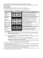
6˚
to 4
45˚
A
B
C
43˚
D
to 4
5˚
Fig. 6-2-2 Relations between flare nut and flare seal surface
2. Flare Connecting Procedures and Precautions
a) Make sure that the flare and union portions do not have any scar or dust, etc.
b) Correctly align the processed flare surface with the union axis.
c) Tighten the flare with designated torque by means of a torque wrench.
The tightening torque for R410A is the same as that for conventional R22.
Incidentally, when the torque is weak, the gas leakage may occur.
When it is strong, the flare nut may crack and may be made non-removable.
When choosing the tightening torque, comply with values designated by manufacturers.
Table 6-2-6 shows reference values.
NOTE
When applying oil to the flare surface, be sure to use oil designated by the manufacturer.
If any other oil is used, the lubricating oils may deteriorate and cause the compressor to burn out.
Table 6-2-6 Tightening torque of flare for R410A [Reference values]
Nominal
diameter
Outer diameter
(mm)
Tightening torque
N•m (kgf•m)
Tightening torque of torque
wrenches available on the market
N•m (kgf•m)
1/4
6.4
14 to 18 (1.4 to 1.8)
16 (1.6), 18 (1.8)
3/8
9.5
33 to 42 (3.3 to 4.2)
42 (4.2)
1/2
12.7
50 to 62 (5.0 to 6.2)
55 (5.5)
5/8
15.9
63 to 77 (6.3 to 7.7)
65 (6.5)
3/4
19.1
100 to 120 (10.0 to 12.0)
——
– 24 –
6-3. Tools
6-3-1. Required Tools
Refer to the “4. Tools”
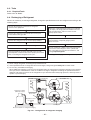
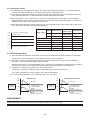
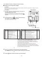
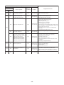
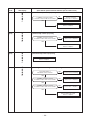
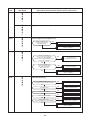
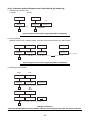
6-4. Recharging of Refrigerant
When it is necessary to recharge refrigerant, charge the specified amount of new refrigerant according to the
following steps.
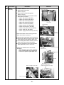
Recover the refrigerant, and check no refrigerant
remains in the equipment.
When the compound gauge’s pointer has indicated
–0.1 Mpa (–76 cmHg), place the handle Low in the
fully closed position, and turn off the vacuum
pump’s power switch.
Connect the charge hose to packed valve service port
at the outdoor unit’s gas side.
Keep the status as it is for 1 to 2 minutes, and
ensure that the compound gauge’s pointer
does not return.
Connect the charge hose of the vacuum pump adapter.
Open fully both packed valves at liquid and gas sides.
Place the handle of the gauge manifold Low in the fully
opened position, and turn on the vacuum pump’s power switch.
Then, evacuating the refrigerant in the cycle.
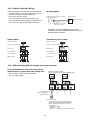
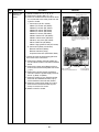
Set the refrigerant cylinder to the electronic balance,
connect the connecting hose to the cylinder and
the connecting port of the electronic balance, and
charge liquid refrigerant.
(For refrigerant charging, see the figure below.)
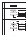
1) Never charge refrigerant exceeding the specified amount.
2) If the specified amount of refrigerant cannot be charged, charge refrigerant bit by bit in COOL mode.
3) Do not carry out additional charging.
When additional charging is carried out if refrigerant leaks, the refrigerant composition changes in the refrigeration cycle, that is characteristics of the air conditioner changes, refrigerant exceeding the specified amount is
charged, and working pressure in the refrigeration cycle becomes abnormally high pressure, and may cause a
rupture or personal injury.
(INDOOR unit)
(Liquid side)
(OUTDOOR unit)
Opened
(Gas side)
Refrigerant cylinder
(With siphon pipe)
Check valve
Closed
Open/Close valve
for charging
Service port
Electronic balance for refrigerant charging
Fig. 6-4-1 Configuration of refrigerant charging
– 25 –
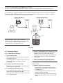
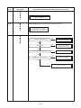
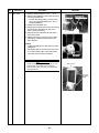
1) Be sure to make setting so that liquid can be charged.
2) When using a cylinder equipped with a siphon, liquid can be charged without turning it upside down.
It is necessary for charging refrigerant under condition of liquid because R410A is mixed type of refrigerant.
Accordingly, when charging refrigerant from the refrigerant cylinder to the equipment, charge it turning the
cylinder upside down if cylinder is not equipped with siphon.
[ Cylinder with siphon ]
[ Cylinder without siphon ]
Gauge manifold
Gauge manifold
OUTDOOR unit
OUTDOOR unit
Refrigerant
cylinder
Refrigerant
cylinder
Electronic
balance
Electronic
balance
Siphon
R410A refrigerant is HFC mixed refrigerant.
Therefore, if it is charged with gas, the composition
of the charged refrigerant changes and the
characteristics of the equipment varies.
Fig. 6-4-2
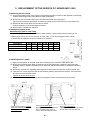
6-5. Brazing of Pipes
6-5-1. Materials for Brazing
1. Silver brazing filler
Silver brazing filler is an alloy mainly composed
of silver and copper.
It is used to join iron, copper or copper alloy, and
is relatively expensive though it excels in
solderability.
2. Phosphor bronze brazing filler
Phosphor bronze brazing filler is generally used
to join copper or copper alloy.
1) Phosphor bronze brazing filler tends to react with
sulfur and produce a fragile compound water
solution, which may cause a gas leakage.
Therefore, use any other type of brazing filler at
a hot spring resort, etc., and coat the surface
with a paint.
2) When performing brazing again at time of
servicing, use the same type of brazing filler.
6-5-2. Flux
1. Reason why flux is necessary
• By removing the oxide film and any foreign
matter on the metal surface, it assists the flow
of brazing filler.
• In the brazing process, it prevents the metal
surface from being oxidized.
• By reducing the brazing filler's surface tension,
the brazing filler adheres better to the treated
metal.
3. Low temperature brazing filler
Low temperature brazing filler is generally called
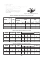
solder, and is an alloy of tin and lead.
Since it is weak in adhesive strength, do not use
it for refrigerant pipes.
– 26 –
2. Characteristics required for flux
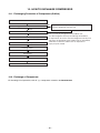
6-5-3. Brazing
• Activated temperature of flux coincides with
the brazing temperature.
• Due to a wide effective temperature range, flux
is hard to carbonize.
• It is easy to remove slag after brazing.
• The corrosive action to the treated metal and
brazing filler is minimum.
• It excels in coating performance and is
harmless to the human body.
As the flux works in a complicated manner as
described above, it is necessary to select an
adequate type of flux according to the type and
shape of treated metal, type of brazing filler and
brazing method, etc.
As brazing work requires sophisticated techniques,
experiences based upon a theoretical knowledge, it
must be performed by a person qualified.
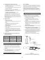
In order to prevent the oxide film from occurring in
the pipe interior during brazing, it is effective to
proceed with brazing while letting dry Nitrogen gas
flow.
Never use gas other than Nitrogen gas.
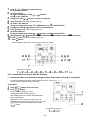
1. Brazing method to prevent oxidation
3. Types of flux
• Noncorrosive flux
Generally, it is a compound of borax and boric
acid.
It is effective in case where the brazing
temperature is higher than 800°C.
• Activated flux
Most of fluxes generally used for silver brazing
are this type.
It features an increased oxide film removing
capability due to the addition of compounds
such as potassium fluoride, potassium chloride
and sodium fluoride to the borax-boric acid
compound.
4. Piping materials for brazing and used
brazing filler/flux
Piping material
Used brazing filler
Used flux
Copper - Copper
Phosphor copper
Do not use
Copper - Iron
Silver
Paste flux
Iron - Iron
Silver
Vapor flux
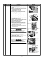
1) Attach a reducing valve and a flow-meter to
the Nitrogen gas cylinder.
2) Use a copper pipe to direct the piping
material, and attach a flow-meter to the
cylinder.
3) Apply a seal onto the clearance between the
piping material and inserted copper pipe for
Nitrogen in order to prevent backflow of the
Nitrogen gas.
4) When the Nitrogen gas is flowing, be sure to
keep the piping end open.
5) Adjust the flow rate of Nitrogen gas so that it
is lower than 0.05 m³/Hr or 0.02 MPa
(0.2kgf/cm²) by means of the reducing valve.
6) After performing the steps above, keep the
Nitrogen gas flowing until the pipe cools down
to a certain extent (temperature at which
pipes are touchable with hands).
7) Remove the flux completely after brazing.
M Flow meter
Stop valve
Nitrogen gas
cylinder
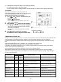
1) Do not enter flux into the refrigeration cycle.
2) When chlorine contained in the flux remains
within the pipe, the lubricating oil deteriorates.
Therefore, use a flux which does not contain
chlorine.
3) When adding water to the flux, use water which
does not contain chlorine
(e.g. distilled water or ion-exchange water).
4) Remove the flux after brazing.
From Nitrogen cylinder
Pipe
Nitrogen
gas
Rubber plug
Fig. 6-5-1
Prevention of oxidation during brazing
– 27 –
6-6. Instructions for Re-use Piping of R22 or R407C
Instruction of Works:
The existing R22 and R407C piping can be
reused for our digital inverter R410A products
installations.
NOTE)
Confirmation of existence of scratch or dent of the
former pipes to be applied and also confirmation of
reliability of the pipe strength are conventionally
referred to the local site.
If the definite conditions can be cleared,
it is possible to update the existing R22 and
R407C pipes to those for R410A models.
6-6-1. Basic Conditions Needed to Reuse the
Existing Pipe
Check and observe three conditions of the refrigerant
piping works.
1. Dry
(There is no moisture inside of the pipes.)
2. Clean (There is no dust inside of the pipes.)
3. Tight (There is no refrigerant leak.)
6-6-2. Restricted Items to Use the Existing Pipes
In the following cases, the existing pipes cannot be
reused as they are. Clean the existing pipes or exchange them with new pipes.
1. When a scratch or dent is heavy, be sure to use the
new pipes for the works.
2. When the thickness of the existing pipe is thinner
than the specified “Pipe diameter and thickness” be
sure to use the new pipes for the works.
• The operating pressure of R410A is high
(1.6 times of R22 and R407C). If there is a scratch
or dent on the pipe or thinner pipe is used, the
pressure strength is poor and may cause breakage of the pipe at the worst.
∗ Pipe diameter and thickness (mm)
Pipe outer diameter
Ø6.4
Ø9.5 Ø12.7 Ø15.9 Ø19.0
R410A
Thickness
R22
(R407C)
0.8
0.8
0.8
1.0
1.0
• In case that the pipe diameter is Ø12.7 mm or
less and the thickness is less than 0.7 mm, be
sure to use the new pipes for works.
3. The pipes are left as coming out or gas leaks.
(Poor refrigerant)
• There is possibility that rain water or air including
moisture enters in the pipe.
4. Refrigerant recovery is impossible.
(Refrigerant recovery by the pump-down operation
on the existing air conditioner)
• There is possibility that a large quantity of poor oil
or moisture remains inside of the pipe.
5. A dryer on the market is attached to the existing pipes.
• There is possibility that copper green rust
generated.
6. Check the oil when the existing air conditioner was
removed after refrigerant had been recovered.
In this case, if the oil is judged as clearly different
compared with normal oil
• The refrigerator oil is copper rust green :
There is possibility that moisture is mixed with the
oil and rust generates inside of the pipe.
• There is discolored oil, a large quantity of the
remains, or bad smell.
• A large quantity of sparkle remained wear-out
powder is observed in the refrigerator oil.
7. The air conditioner which compressor was exchanged due to a faulty compressor.
When the discolored oil, a large quantity of the
remains, mixture of foreign matter, or a large
quantity of sparkle remained wear-out powder is
observed, the cause of trouble will occur.
8. Installation and removal of the air conditioner are
repeated with temporary installation by lease and
etc.
9. In case that type of the refrigerator oil of the
existing air conditioner is other than the following oil
(Mineral oil), Suniso, Freol-S, MS (Synthetic oil),
alkyl benzene (HAB, Barrel-freeze), ester series,
PVE only of ether series.
• Winding-insulation of the compressor may
become inferior.
NOTE)
The above descriptions are results of confirmation by
our company and they are views on our air
conditioners, but they do not guarantee the use of the
existing pipes of the air conditioner that adopted
R410A in other companies.
6-6-3. Branching Pipe for Simultaneous
Operation System
• In the concurrent twin system, when TOSHIBAspecified branching pipe is used, it can be reused.
Branching pipe model name:
RBC-TWP30E2, RBC-TWP50E2
On the existing air conditioner for simultaneous
operation system (twin system), there is a case of
using branch pipe that has insufficient compressive
strength. In this case please change it to the branch
pipe for R410A.
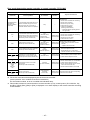
6-6-4. Curing of Pipes
When removing and opening the indoor unit or outdoor
unit for a long time, cure the pipes as follows:
• Otherwise rust may generate when moisture or
foreign matter due to dewing enters in the pipes.
• The rust cannot be removed by cleaning, and a new
piping work is necessary.
– 28 –
Place position
Outdoors
Indoors
Term
Curing manner
1 month or more
Pinching
Less than 1 month
Every time
Pinching or taping
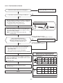
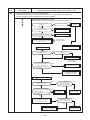
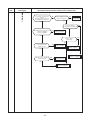
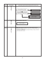
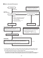
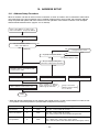
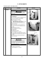
6-6-5. Final Installation Checks
Is there no scratch or dent on the existing pipes?
Existing pipe: NO * Use a new pipes.
NO
Is it possible to operate the existing air conditioner?
YES
∗ After the existing air conditioner operated in cooling mode
for approx. 30 minutes or longer*, recover the refrigerant.
∗ For cooling the pipes and recovering of oil
• Refrigerant recovery: Pump down method
Nitrogen gas pressure 0.5 Mpa
∗ Remove the existing air conditioner from the piping and
carry out flashing (nitrogen pressure 0.5 Mpa) to remove
the remains inside of the pipe.
Note] In case of twin, also be sure to flash the
branching pipe.
(If there is discharge of remains,
it is judged that there is a large quantity of remains.)
Was not largely discolored oil or
a large quantity of remains discharged?
(When the oil deteriorates, the color of the
oil changes to muddy and black color.)
NO
Clean the pipes or use the new pipes.
If you are in trouble of
pipe cleaning, please contact us.
YES
Connect the indoor/outdoor units to the existing pipe.
• Use a flare nut attached to the main unit for the
indoor/outdoor units.
(Do not use the flare nut of the existing pipe.)
• Re-machine the flare machining size to size for R410A.
Piping necessary to change the flare nut/
machining size due to pipe compression.
∗ In case that a gas pipe Ø19 mm or bigger is used for the
outdoor unit of SM80 (3 HP) : (Our R410A model 3 to 6 HP
gas pipe size is Ø15.9 mm)
1) Flare nut width: H
See page 9-3-2.
H
∗ (Airtight test), Vacuum dry, Refrigerant charge,
Gas leak check
(mm)
Copper pipe
outer dia.
Ø6.4
Ø9.5
Ø12.7
Ø15.9
Ø19.1
For R410A
17
22
26
29
36
24
27
Same
as above
For R22
Same as above
2) Flare machining size: A
A
Trial run
(mm)
Copper pipe
outer dia.
Ø6.4
Ø9.5
Ø12.7
Ø15.9
Ø19.1
For R410A
9.1
13.2
16.6
19.7
24.0
For R22
9.0
13.0
16.2
19.4
23.3
Becomes large a little for R410A
Do not apply the refrigerator oil to the flare surface.
– 29 –
6-6-6. Handling of Existing Pipe
When using the existing pipe, carefully check it for the following:
• Wall thickness (within the specified range)
• Scratches and dents
• Water, oil, dirt, or dust in the pipe
• Flare looseness and leakage from welds
• Deterioration of copper pipe and heat insulator
Cautions for using existing pipe
• Do not reuse the flare to prevent gas leak.
Replace it with the supplied flare nut and then process it to a flare.
• Blow nitrogen gas or use an appropriate means to keep the inside of the pipe clean.
If discolored oil or much residue is discharged, wash the pipe.
• Check welds, if any, on the pipe for gas leak.
When the pipe corresponds to any of the following, do not use it. Install a new pipe instead.
• The pipe has been open (disconnected from indoor unit or outdoor unit) for a long period.
• The pipe has been connected to an outdoor unit that does not use refrigerant R22, R410A or R407C.
• The existing pipe must have a wall thickness equal to or larger than the following thickness.
Reference outside diameter
(mm)
Wall thickness
(mm)
Ø9.5
0.8
Ø15.9
1.0
Ø19.1
1.0
• Never use any pipe with a wall thickness less than these thicknesses due to insufficient pressure capacity.
– 30 –
High-pressure
SW connector
CN501 (Green)
Reactor lead wire (White)
P26, P27
Power supply circuit
protection fuse
F03 (250V, 3.15A,
Plastic case)
Electrolyte capacitor
Fan motor
output
CN300
(White)
Compressor
output lead
P03, P04, P05
– 31 –
Varistor
protection fuse
F23 (250V, 6.3A)
Inter-unit wire
protective fuse
F22 (250V, 10A)
Power supply
connecting lead wire
P21 (White)
P20 (Red)
Indoor unit
connecting lead wire
P24 (Gray)
P23 (White)
P22 (Red)
4-way valve connector
CN700 (Yellow)
Case thermo
connector
CN500 (Blue)
PMVconnector
CN701 (White)
Optional P.C. board
Connection connector
CN806
Temp. sensor
connector
TD: CN601 (White)
TO: CN602 (Yellow)
TE: CN603 (White)
TS: CN604 (White)
TL: CN605 (White)
Power protection fuse
F20 (250V, 25A)
Service switch
SW800
SW801
Lead wire for grounding
P25 (Black)
Power error
display LED
D800 to 804 (Yellow)
D805 (Green)
Reactor lead wire (Gray)
P28, P29
Jumper wire
J800 to J804, J806
7.CIRCUIT CONFIGURATION AND CONTROL SPECIFICATIONS
7-1. Outdoor unit control
7-1-1. Prim circuit board (MCC-1630)
7-1-2. Outline of Main Controls
1. Pulse Modulating Valve (PMV) control
1) For PMV with 50 to 500 pulses during operation, respectively.
2) In cooling operation, PMV is controlled with the temperature difference between TS sensor and TC
sensor.
3) In heating operation, PMV is controlled with the temperature difference between TS sensor and TE
sensor.
4) For the temperature difference in items 2) and 3), 1 to 5K is aimed as the target in both cooling and
heating operations.
5) When the cycle excessively rose in both cooling and heating operations, PMV is controlled by TD
sensor.
The aimed value is usually 92°C for SM110, SM140 in both cooling and heating operations.
REQUIREMENT
A sensor trouble may cause a liquid back-flow or abnormal overheat resulting in excessive shortening of the
compressor life. In a case of trouble on the compressor, be sure to check there is no error in the resistance
value an the refrigerating cycle of each sensor after repair and then start the operation.
2. Discharge temperature release control
1) When the discharge temperature did not fall or the discharge temperature rapidly went up by PMV
control, this control lowers the operation frequency. It subdivides the frequency control up to 0.6Hz to
stabilize the cycle.
2) When the discharge temperature detected an abnormal stop zone, the compressor stops and then
restarts after 2 minutes 30 seconds.
The error counting is cleared when the operation continued for 10 minutes. If the error is detected by
4 times without clearing, the error is determined and restarting is not performed.
∗ The cause is considered as excessively little amount of refrigerant, PMV error or clogging of the cycle.
3) For displayed contents of error, confirm on the check code list.
TD [˚C]
Abnormal stop
111
Frequency normal down
109
Frequency slow down
106
Frequency hold
103
96
Frequency slow up
(Up to command)
As command is
– 32 –
3. Current release control
The output frequency and the output voltage are controlled by AC current value detected by T20 on the
outdoor P.C. board so that input current of the inverter does not exceed the specified value.
Current [A]
Frequency down
I1
I1 – 0.5
Objective model
Hold
Hold
Normal operation
I1 value [A]
SM110
SM140
COOL HEAT
COOL HEAT
20.4
21.2
21.2
21.2
4. Outdoor fan control
Allocations of fan tap revolutions [rpm]
W1
W2
W3
W4
W5
W6
W7
W8
W9
WA
WB
WC
WD
WE
WF
SM110
250
280
320
360
410
460
520
580
640
700
760
880
880
900
930
SM140
250
280
320
360
410
460
520
580
640
700
760
880
880
900
970
4-1. Cooling fan control
1) An outdoor fan is controlled by TL sensor, TO sensor and operation frequency. An outdoor fan is controlled at 1-tap interval of DC fan control.
2) At the start time, the fan is fixed for 60 seconds only with the maximum fan tap corresponded to the zone
in the following table but it is controlled with TL sensor temperature after then.
Temp. range
SM110 Under 30.0 Hz
Over 30.0,
under 43.8 Hz
Over 43.8 Hz
SM140 Under 34.2 Hz
Over 34.2,
under 52.2 Hz
Over 52.2 Hz
MIN.
MAX.
MIN.
MAX.
WA
SM110:WD
SM140:WF
MIN.
TL
58˚C
55˚C
38˚C
35˚C
WF tap
+ 1 tap / 20 sec (Up to the maximum
rotational frequency of each zone)
Rotational frequency hold
– 1 tap / 20 sec
(Up to the minimum rotational
frequency of each zone)
MAX.
38˚C ≤ TO
W6
WB
W8
SM110:WD
SM140:WF
29˚C ≤ TO < 38˚C
W5
WA
W7
WD
W9
SM110:WD
SM140:WF
15˚C ≤ TO < 29˚C
W3
W7
W5
W9
W7
WB
5˚C ≤ TO < 15˚C
W2
W5
W4
W7
W6
W9
0˚C ≤ TO < 5˚C
W1
W3
W3
W5
W4
W7
– 4˚C ≤ TO < 0˚C
W1
W2
W2
W4
W3
W5
TO < – 4˚C
OFF
OFF
OFF
OFF
OFF
OFF
TO error
OFF
WB
OFF
SM110:WD
SM140:WF
OFF
SM110:WD
SM140:WF
– 33 –
4-2. Heating fan control
1) An outdoor fan is controlled by TE sensor, TO sensor and operation frequency. (It is controlled with W1
for minimum and the maximum is controlled according to the following table.)
2) At the start time, the fan is fixed for 3 minutes only with the maximum fan tap corresponded to the zone
in the following table but it is controlled with TE sensor temperature after then.
3) When a status TE ≥ 24°C continues for 5 minutes, the operation stops. In this case, no error display
appears and the status is same as the normal thermo-OFF. The can restarts after approx. 2 minutes 30
seconds and this continuous operation is not an error.
4) When the above status as 3) occurs frequently, it is considered that filter of the suction part of the indoor
unit is dirty. Clean the filter and restart the operation.
TE – 2 tap / 20 seconds (up to W1)
Stop timer count
24˚C
– 2 tap / 20 seconds (up to W1)
21˚C
18˚C
15˚C
Temp. range
SM110 Under 31.2 Hz
Over 31.2,
under 47.4 Hz
Over 47.4 Hz
SM140 Under 36.0 Hz
Over 36.0,
under 55.8 Hz
Over 55.8 Hz
MAX.
MAX.
MAX.
W7
W8
W9
10˚C ≤ TO
– 1 tap / 20 seconds (up to W1)
Rotational frequency hold
+ 1 tap / 20 seconds
(up to Max. tap of each zone)
5˚C ≤ TO < 10˚C
W9
WB
WF
– 3˚C ≤ TO < 5˚C
WF
WF
WF
– 10˚C ≤ TO < – 3˚C
WF
WF
WF
TO < – 10˚C
WF
WF
WF
TO error
WF
WF
WF
5. Coil heating control
1) This control function heats the compressor by turning on the stopped compressor instead of a case heater.
It purposes to prevent stagnation of the refrigerant inside of the compressor.
2) As usual, turn on power of the compressor for the specified time before a test run after installation;
otherwise a trouble of the compressor may be caused.
As same as a test run, it is recommended to turn on power of the compressor beforehand when starting
operation after power of the compressor has been interrupted and left as it is for a long time.
3) A judgment for electricity is performed by TD and TO sensors.
If TO sensor is defective, a backup control is automatically performed by TE sensor.
For a case of defective TO sensor, judge it with outdoor LED display.
4) For every model, the power is turned off when TD is 30°C or more.
TO
0˚C
(Normal time)
TE
2˚C
No power
• Power-ON
condition
TD<30˚C
– 1˚C
– 2˚C
– 3˚C
(In defective TO sensor)
No power
Intermittent power-ON
10 minutes: ON /
5 minutes: OFF
Output
[24W or equivalent]
Continuous power-ON
Output
[24W or equivalent]
• Power-ON
condition
TD < 30˚C
1˚C
0˚C
– 1˚C
REQUIREMENT
While heating the coil, the power sound may be heard. However it is not a trouble.
– 34 –
Intermittent power-ON
10 minutes: ON /
5 minutes: OFF
Output
[24W or equivalent]
Continuous power-ON
Output
[24W or equivalent]
6. Short intermittent operation preventive control
1) For 3 to 10 minutes after operation start, in some cases, the compressor does not stop to protect the
compressor even if receiving the thermostat-OFF signal from indoor.
However it is not abnormal status. (The operation continuance differs according to the operation status.)
2) When the operation stops by the remote controller, the operation does not continue.
Current release control value (II1)
7. Current release value shift control
1) This control purposes to prevent troubles of
the electronic parts such as the compressor
driving elements and the compressor during
cooling operation.
2) The current release control value (I1) is
selected from the following table according to
TO sensor value.
[A]
Temperature range
SM110
SM140
47°C ≤ TO
15.0
15.5
44°C ≤ TO < 47°C
16.8
17.4
39°C ≤ TO < 44°C
17.7
18.3
TO error
15.0
15.5
8. Over-current protective control
1)
2)
3)
4)
When the over-current protective circuit detected an abnormal current, stop the compressor.
The compressor restarts after 2 minutes 30 seconds setting [1] as an error count.
When the error count [8] was found, determine an error and restart operation is not performed.
For the error display contents, confirm on the check code list.
9. High-pressure release control
1) The operation frequency is controlled to restrain abnormal rising of high pressure by TL sensor in
cooling operation and TC sensor in heating operation.
2) When TL sensor in cooling operation or TC sensor in heating operation detects abnormal temperature of
the stop zone, stop the compressor and the error count becomes +1.
3) When the compressor stopped with 2), the operation restarts from the point of the normal operation
zone (e point or lower) where it returned after 2 minutes 30 seconds.
4) The error count when the compressor stopped with 2) is cleared after the operation continued for
10 minutes.
If the error count becomes [10] without clearing, the error is determined and reactivation is not performed.
5) For the error display contents, confirm on the check code list.
HEAT TC / COOL TL
[˚C]
a
b
c
d
e
Abnormal stop
HEAT
COOL
TC
TL
Frequency normal down
a
62°C
63°C
Frequency slow down
b
57°C
62°C
Frequency hold
c
55°C
60°C
Frequency slow up (Up to command)
d
53°C
58°C
As command is
e
49°C
54°C
10. Defrost control
c In heating operation, defrost operation is performed when TE sensor temperature satisfies any condition
d
e
in A zone to D zone.
The defrost operation is immediately finished if TE sensor temperature has become 12°C or more, or it
also is finished when condition of 7°C < TE < 12°C has continued for 1 minute. The defrost operation is
also finished when defrost operation has continued for 10 minutes even if TE sensor temperature has
become 7°C or lower.
After defrost operation has finished, the compressor and the outdoor fan start heating operation after
stopped for approx. 40 seconds.
– 35 –
Start of heating operation
0
10
15
c
b
a
d
[min.]
TE [˚C]
–5
A zone
– 10
– 13
B zone
– 18
D zone
*
C zone
* From 10 minutes to 15 minutes after a heating operation started, the minimum value of TE is stored in
memory as TEO and the minimum temperature of TO as ToO.
At normal TO
At error TO
A zone
When status of [(TEO – TE) – (ToO – TO) ≥ 3˚C]
continued for 20 seconds
When status of [(TEO – TE) ≥ 3˚C]
continued for 20 seconds
B zone
When status of [(TEO – TE) – (ToO – TO) ≥ 2˚C]
continued for 20 seconds
When status of [(TEO – TE) ≥ 2˚C]
continued for 20 seconds
C zone
When status of [TE ≤ – 18˚C] continued for 20 seconds
D zone
When compressor operation status with TE ≤ – 13˚C are added by d times
SM110, SM140
a
55
b
39
c
29
d
90
11. High-pressure switch
1) When the high-pressure switch operates, the operation of the compressor is terminated.
2) The compressor restarts after 5 minutes using [1] as an error count.
After restart, the error count is cleared when operation continues for 10 minutes or more.
3) An error is confirmed with the error count [10].
4) For the indicated contents of error, confirm using the check code table.
12 Control of compressor case thermo
1) The compressor stops when the case thermo of the compressor operated.
2) When the case thermo operated for approx. 80 seconds, E04 error code (same as serial error) is
displayed on the wired remote controller. → Refer to the Check Code.
3) When the case thermo is reset, the operation restarts.
– 36 –
8. TROUBLESHOOTING
8-1. Summary of Troubleshooting
<Wired remote controller type>
1. Before troubleshooting
1) Required tools/instruments
• + and – screwdrivers, spanners, radio cutting pliers, nippers, push pins for reset switch
• Tester, thermometer, pressure gauge, etc.
2) Confirmation points before check
a) The following operations are normal.
1. Compressor does not operate.
• Is not 3-minutes delay (3 minutes after compressor OFF)?
• Is not the outdoor unit in standby status though the remote controller reached the setup
temperature?
• Does not timer operate during fan operation?
• Is not an overflow error detected on the indoor unit?
• Is not outside high-temperature operation controlled in heating operation?
2. Indoor fan does not rotate.
• Does not cool air discharge preventive control work in heating operation?
3. Outdoor fan does not rotate or air volume changes.
• Does not high-temperature release operation control work in heating operation?
• Does not outside low-temperature operation control work in cooling operation?
• Is not defrost operation performed?
4. ON/OFF operation cannot be performed from remote controller.
• Is not the control operation performed from outside/remote side?
• Is not automatic address being set up?
(When the power is turned on at the first time or when indoor unit address setting is changed,
the operation cannot be performed for maximum approx. 5 minutes after power-ON.)
• Is not being carried out a test run by operation of the outdoor controller?
b) Did you return the cabling to the initial positions?
c) Are connecting cables of indoor unit and remote controller correct?
2. Troubleshooting procedure
When a trouble occurred, check the parts along with the following procedure.
Trouble
→
Confirmation of check code display
→
Check defective position and parts.
NOTE
For cause of a trouble, power conditions or malfunction/erroneous diagnosis of microcomputer due to outer
noise is considered except the items to be checked.
If there is any noise source, change the cables of the remote controller to shield cables.
– 37 –
<Wireless remote controller type>
1. Before troubleshooting
1) Required tools/instruments
• + and – screwdrivers, spanners, radio cutting pliers, nippers, etc.
• Tester, thermometer, pressure gauge, etc.
2) Confirmation points before check
a) The following operations are normal.
1. Compressor does not operate.
• Is not 3-minutes delay (3 minutes after compressor OFF)?
• Is not the outdoor unit in standby status though the remote controller reached the setup
temperature?
• Does not timer operate during fan operation?
• Is not an overflow error detected on the indoor unit?
• Is not outside high-temperature operation controlled in heating operation?
2. Indoor fan does not rotate.
• Does not cool air discharge preventive control work in heating operation?
3) Outdoor fan does not rotate or air volume changes.
• Does not high-temperature release operation control work in heating operation?
• Does not outside low-temperature operation control work in cooling operation?
• Is not defrost operation performed?
4) ON/OFF operation cannot be performed from remote controller.
• Is not forced operation performed?
• Is not the control operation performed from outside/remote side?
• Is not automatic address being set up?
• Is not being carried out a test run by operation of the outdoor controller?
a) Did you return the cabling to the initial positions?
b) Are connecting cables between indoor unit and receiving unit correct?
2. Troubleshooting procedure
(When the power is turned on at the first time or when indoor unit address setting is changed, the operation
cannot be performed for maximum approx. 5 minutes after power-ON.)
When a trouble occurred, check the parts along with the following procedure.
Trouble
→
Confirmation of lamp display
(EX : When 4-way air discharge cassette type
wireless remote controller is connected)
→
Check defective
position and parts.
1) Outline of judgment
The primary judgment to check where a trouble occurred in indoor unit or outdoor unit is performed with
the following method.
Method to judge the erroneous position by flashing indication on the display part of indoor unit
(sensors of the receiving unit)
The indoor unit monitors operating status of the air conditioner, and the blocked contents of self-diagnosis
are displayed restricted to the following cases if a protective circuit works.
– 38 –
8-2. Troubleshooting
8-2-1. Outline of judgment
The primary judgment to check whether a trouble occurred in the indoor unit or outdoor unit is carried out with
the following method.
Method to judge the erroneous position by flashing indication on the display part of the indoor unit
(sensors of the receiving part)
The indoor unit monitors the operating status of the air conditioner, and the blocked contents of self-diagnosis
are displayed restricted to the following cases if a protective circuit works.
: Go off,
Lamp indication
Operation Timer
: Go on,
: Flash (0.5 sec.)
Cause of tr oub le occurrence
Check code
Ready
—
Power supply OFF or miswiring between receiving unit and indoor unit
No indication at all
E01
E02
Operation Timer
Ready
Flash
Operation Timer
Receiving error ⎫
⎬ Receiving unit
Sending error ⎭
⎫
⎬
⎭
Miswiring or wire connection error
between receiving unit and indoor unit
E03
Communication stop
E08
Duplicated indoor unit No.
E09
Duplicated header units of remote controller
E10
Communication error between CPUs on indoor unit P.C. board
E18
Wire connection error between indoor units, Indoor power OFF
(Communication stop between indoor master and follower or between main
and sub indoor twin)
Ready
E04
Setup error
Miswiring between indoor unit and outdoor unit or connection erorr
(Communication stop between indoor and outdoor units)
Outdoor unit case thermostat work on
................ Comp. overheating
Outdoor wiring error
Flash
Operation Timer
Ready
P01
P10
Alternate flash
P12
Ready
Alternate flash
1:
⎫
⎬
⎭
Protective device of indoor unit worked.
P04
Outdoor unit discharge temp. error
Case thermostat work on,
Power error, High pressure protection
P05
Negative phase detection error
P07
Heat sink overheat error
P15
Gas leak detection error
P19
4-way valve system error (Indoor or outdoor unit judged.)
P20
Outdoor unit high pressure protection
P22
Outdoor unit: Outdoor unit fan error
P26
Outdoor unit: Inverter Idc operation
P29
Outdoor unit: Position detection error
P31
Stopped because of error of other indoor unit in a group
(Check codes of E03/L03/L07/L08)
P03
Operation Timer
Overflow was detected.
Indoor DC fan error
⎫
⎬
⎭
⎫
⎬
⎭
Protective device of
outdoor unit worked.
*1
Outdoor unit error
⎫
⎬
⎭
Protective device of
outdoor unit worked.
*1
These are representative examples and the check code differs according to the outdoor unit to be combined.
– 39 –
Lamp indication
Operation Timer
Ready
Alternate flash
Operation Timer
Ready
Alternate flash
Operation Timer
Check code
Cause of trouble occurrence
F01
Heat exchanger sensor (TCJ) error
F02
Heat exchanger sensor (TC) error
P10
Heat exchanger sensor (TA) error
F04
Discharge temp. sensor (TD) error
F06
Temp. sensor (TE) error
F07
Temp. sensor (TL) error
F08
Temp. sensor (TO) error
F12
Temp. sensor (TS) error
F13
Temp. sensor (TH) error
F15
Temp. Sensor miswiring (TE, TS)
F29
Indoor EEPROM error
F31
Outdoor EEPROM error
H01
Compressor break down
H02
Compressor lock
⎫ Outdoor compressor system error
⎬
⎭
H03
Current detection circuit error
} Power supply, outdoor P.C. board error
⎫
⎪
⎬
⎪
⎭
Indoor unit sensor error
⎫
⎪
⎪
⎪
⎪
⎪
⎬
⎪
⎪
⎪
⎪
⎪
⎭
Sensor error of outdoor unit
∗1
Ready
Simultaneous flash
Operation Timer
Ready
Simultaneous flash
Operation Timer
Ready
Flash
L03
Operation Timer
Ready
L07
Operation Timer
Ready
Simultaneous flash
⎫
⎪
There is indoor unit of group connection ⎬ → AUTO address
⎪
in individual indoor unit.
* If group construction and
⎭
Duplicated header indoor units
L08
Unsetting of group address
L09
Missed setting
(Unset indoor capacity)
L10
Unset model type (Service board)
L20
Duplicated indoor central addresses
L30
Outside interlock error
Simultaneous flash
∗1
address are not normal
power supply turned on,
automatically goes to
address setup mode.
∗1: These are representative examples and the check code differs according to the outdoor unit to be combined.
8-2-2. Others (Other than Check Code)
Lamp indication
Operation Timer
Check code
Cause of trouble occurrence
Ready
—
During test run
—
Disagreement of cool/heat
(Automatic cool/heat setting to automatic cool/heat prohibited model, or
setting of heating to cooling-only model)
Simultaneous flash
Operation Timer
Ready
Alternate flash
– 40 –
8-2-3. Monitor Function of Remote Controller Switch
Calling of sensor temperature display
<Contents>
Each data of the remote controller, indoor unit and outdoor unit can be understood by calling the service
monitor mode from the remote controller.
<Procedure>
1
2
TEST
<RBC-AMT32E>
CL
Push
+
buttons simultaneously for 4 seconds to
call the service monitor mode.
The service monitor goes on, the master indoor unit No. is
displayed at first and then the temperature of CODE No. 00 is
displayed.
TEMP.
Ø
ON / OFF
TIMER SET
TEMP.
Push temperature set
buttons and then change
the CODE No. of data to be monitored.
The CODE No. list is shown below.
TIME
FILTER
L
RESET TEST
2
SET
4
CL
FAN
MODE
SAVE
A
VENT
SWING/FIX
UNIT
T LOUVER
1
3
<Operation procedure>
1
2
3
4
Returned to usual display
Indoor unit data
01
Unit
CODE No.
Data name
Unit
°C
60
61
62
63
65
6A
∗ 6D
∗ 70
∗ 72
∗ 73
F1
Outdoor heat exchanger (Coil) temperature (TE)
Outside temperature (TO)
Compressor discharge temperature (TD)
Compressor suction temperature (TS)
Heat sink temperature (TH)
Operation current (× 1/10)
Outdoor heat exchanger (Coil) temperature (TL)
Compressor operation frequency
Outdoor fan revolution frequency (Lower)
Outdoor fan revolution frequency (Upper)
Compressor calculated operation time
°C
°C
°C
°C
°C
A
°C
rps
rpm
rpm
×100h
02
03
04
∗ 07
∗ F2
F3
∗ F8
°C
°C
°C
rpm
×100h
×1h
°C
Outdoor unit data
Data name
Room temperature
(Remote controller)
Indoor suction temperature (TA)
Indoor heat exchanger (Coil)
temperature (TCJ)
Indoor heat exchanger (Coil)
temperature (TC)
Indoor fan revolution frequency
Indoor fan calculated operation time
Filter sign time
Indoor discharge temperature*1
(4-way only)
CODE No.
• The CODE No. with ∗ marks in the above table are displayed only
on the indoor units of 4 series models and after.
(4 series indoor units mean RAV-SM1404UT-E for example.).
• The indoor discharge temperature of CODE No. [F8] is the estimated value from TC or TCJ sensor.
Use this value to check discharge temperature at test run.
(A discharge temperature sensor is not provided to this model.)
• The data value of each item is not the real time, but value delayed
by a few seconds to ten-odd seconds.
3
4
Ø
UNIT LOUVER
Push
button to select the indoor unit to be monitored.
Each data of the indoor unit and its outdoor units can be monitored.
Ø
Pushing
TEST
button returns the status to the usual display.
– 41 –
– 42 –
P05
P07
P15
P20
P22
P26
P29
E01
E02
E03
E04
E08
E09
E10
E18
L03
L07
L08
L09
L30
P19
AF
1C
AE
22
1A
14
16
97
−
97
04
96
99
CF
97,99
96
99
99
46
66
08
P04
21
H02
H03
1d
17
L10
H01
1F
P03
F08
F07
F12
F13
F15
F31
1d
18
A2
43
18
IC
88
F06
18
ALT
SIM
SIM
SIM
SIM
SIM
ALT
ALT
ALT
ALT
ALT
ALT
ALT
ALT
ALT
SIM
ALT
ALT
ALT
ALT
ALT
SIM
Outside temp. sensor (TO) error
Temp. sensor (TL) error
Temp. sensor (TS) error
Temp. sensor (TH) error
Misconnection of temp. sensor (TE, TS)
EEPROM error
4-way valve inverse error
Communication error between CPU
Regular communication error between master and
follower indoor units
Duplicated indoor master units
There is group cable in individual indoor unit.
Unset indoor group address
Unset indoor capacity
Outside error input to indoor unit (Interlock)
Duplicated main remote controllers
Duplicated indoor addresses
Regular communication error between indoor and
remote controller
Indoor/Outdoor serial error, Case thermostat operation
of the outdoor unit occurred
Remote controller send error
Outdoor unit Discharge temp. error
Outdoor unit
High pressure system error, Power supply voltage error
Power supply error
Outdoor unit Heat sink overheat
Gas leak detection
Outdoor unit High pressure system error
Outdoor unit Outdoor fan error
Outdoor unit Inverter Idc operation
Outdoor unit Position detection error
No remote controller master unit
Remote controller communication error
Outdoor unit Setting error of service P.C. board type
Outdoor unit Compressor lock
Outdoor unit Current detection circuit error
Outdoor unit Compressor break down
Outdoor unit
Outdoor unit
Outdoor unit
Outdoor unit
Outdoor unit
Outdoor unit
Outdoor unit Temp. sensor (TE, TS, TL) error
Outdoor unit Discharge temp. sensor (TD) error
Representative defective position
Indoor
Indoor
Indoor
Indoor
Indoor
Indoor
Outdoor
Indoor
Indoor
Remote
controller
Indoor
Indoor
Indoor
Outdoor
Outdoor
Outdoor
Outdoor
Outdoor
Outdoor
Outdoor
Remote
controller
Remote
controller
Outdoor
Outdoor
Outdoor
Outdoor
Outdoor
Outdoor
Outdoor
Outdoor
Outdoor
Outdoor
Outdoor
Outdoor
Outdoor
Outdoor
Detection
Explanation of error contents
In heating operation, error was detected by temp. down of indoor heat exchanger or temp. up of TE, TS.
Same address as yours was detected.
In 2-remote controller control, both were set as master.
(Indoor master unit stops warning and follower unit continues operation.)
MCU communication error between main motor and micro computer
Regular communication was impossible between master and follower indoor units.
Communication between twin master (Main unit) and follower (sub unit) was impossible.
There are multiple master units in a group.
When even one group connection indoor unit exists in individual indoor unit
Indoor address group was unset.
Capacity of indoor unit was unset.
Abnormal stop by CN80 outside error input
Serial communication error between indoor and outdoor, Case thermostat operation occurred
No communication from remote controller and network adapter
Signal cannot be sent to indoor unit.
Error was detected by discharge temp. release control.
When case thermostat worked, error was detected by high release control from indoor/
outdoor heat exchanger temp. sensor. Power supply voltage error
Power supply voltage error
Abnormal overheat was detected by outdoor heat sink temp. sensor.
Abnormal overheat of discharge temp. or suction temp. was detected.
Error was detected by high release control from indoor/outdoor heat exchanger temp. sensor.
Error (Over-current, lock, etc.) was detected on outdoor fan drive circuit.
Short-circuited protective operation of compressor drive circuit element (G-Tr /IGBT) worked.
Position detection error of compressor motor was detected.
Signal was not received from indoor unit.
Main remote controller was not set. (including 2 remote controllers)
When outdoor service P.C. board was used, model type select jumper setting was inappropriate.
×
×
×
×
×
×
—
—
×
×
×
×
×
×
×
×
×
×
×
—
—
×
×
×
×
×
×
×
×
×
×
×
×
×
×
×
×
×
×
×
×
×
×
×
×
×
×
×
×
×
×
×
×
×
×
×
×
×
×
×
×
Operation
continuation
Automatic
reset
: Go on, : Flash, : Go off
SIM (Simultaneous): Simultaneous flashing when there are two flashing LED
Open/Short of discharge temp. sensor was detected.
Open/Short of heat exchanger temp. sensor was detected.
Miswiring between TE sensor and TS sensor
Open/Short of outside temp. sensor was detected.
Open/Short of heat exchanger temp. sensor was detected.
Open/Short of suction temp. sensor was detected.
Open/Short of heat sink temp. sensor (Board installed) was detected.
Misconnection of outdoor heat exchanger temp. sensor and suction temp. sensor was detected.
Outdoor P.C. board part (EEPROM) error was detected.
When reached min-Hz by current release control, short-circuited current (Idc) after
DC excitation was detected.
Compressor lock was detected.
Current detection circuit error
ALT (Alternate): Alternate flashing when there are two flashing LED
When this warning was detected before group construction/address check finish at power supply was turned on, the mode shifts automatically to AUTO address setup mode.
ALT
Sensor lamp part
Block indication
Operation Timer Ready Flash
ALT
1E
F04
19
Central
Remote
control
controller
indication indication
8-2-4. Check Code List (Outdoor)
– 43 –
By unit with warning No.
—
—
L20
—
97
98
99
—
—
67
F01
F02
F10
F29
P01
P10
P12
P31
0F
0d
0C
12
11
0b
11
47
SIM
ALT
L
ALT
L
ALT
L
ALT
L
t
Block indication
n
Ready Flash
ALT
L
ALT
L
Remote
controller
Central
control
indication
There are multiple communication adapters.
LAN system communication error
LAN system communication error
Error in indoor group
Indoor unit Heat e
Indoor unit Heat exchanger sensor (TC) error
.
A) error
A
C.
Indoor unit Indoor fan error
Indoor unit Overflow detection
Indoor unit Indoor fan error
Other indoor unit error
Representative defective position
Network adapter
Network adapter/
Network
Network adapter
Indoor
Indoor
Indoor
Indoor
Indoor
Indoor
Indoor
Indoor
Detection
t of heat e
.
Explanation of error contents
SIM (Simultaneous): Sim
There are multiple communication adapters on remote controller communication line.
Duplicated indoor address of central control system communication
—
×
×
×
×
Automatic
reset
×
—
×
×
×
×
×
×
×
×
Operation
continuation
: Go on, : Flash, : Go off
Indoor AC fan error was detected. (Fan thermal relay worked.)
Float switch worked.
as detected.
war
. E03/L07/L03/L08 warning
Sub remote controller error in a group
(Details of remote controller are display
a ed with unit No. Only central control side is display
a ed.)
Communication error of central control system signal
∗
yed on the remote controller
Open/Shor
ALT
L (Alter nate): Alternate flashing when there are two flashing LED
Error mode detected by indoor unit
Operation of diagnostic function
Check
code
E03
Cause of operation
No communication from remote
controller (including wireless) and
communication adapter
Status of
air conditioner
Judgment and measures
Condition
Stop
Displayed when
(Automatic reset) error is detected
The serial signal is not output from
outdoor unit to indoor unit.
• Defective serial sending circuit on
E04
Displayed when
Stop
(Automatic reset) error is detected
1. Check cables of remote controller and communication adapters.
s
• Remote controller LCD display OFF (Disconnection)
• Central remote controller [97] check code
• Inter-unit wire check, correction of miswiring
Check outdoor P.C. board. Correct wiring of P.C. board.
2. When outdoor unit normally operates
Check P.C. board (Indoor receiving / Outdoor sending).
• Defective serial receiving circuit on
indoor P.C. board
Case thermostat operation
* Abnormal overheat of compressor
E08
Duplicated indoor unit address
L03
Duplicated indoor master unit
L07
There is group wire in individual indoor
unit.
L08
Unset indoor group address
L09
Stop
Displayed when
error is detected
1. Check case thermostat and connector.
2. Check gas leak, recharge
3. Check full open of service valve.
4. Check PMV (Pulse Motor Valve).
5. Check broken pipe.
1. Check whether remote controller connection (Group/Individual)
was changed or not after power supply turned on
(Finish of group construction/Address check).
* If group construction and address are not normal when the
power has been turned on, the mode automatically shifts to
address setup mode. (Resetting of address)
Stop
Displayed when
error is detected
Unset indoor capacity
Stop
Displayed when
error is detected
1. Set indoor capacity (CODE No. (DN) = 11)
L30
Abnormal input of outside interlock
Stop
Displayed when
error is detected
1. Check outside devices.
2. Check indoor P.C. board.
P10
Float switch operation
• Float circuit, Disconnection,
Coming-off, Float switch contact error
Stop
Displayed when
error is detected
1. Trouble of drain pump
2. Clogging of drain pump
3. Check float switch.
4. Check indoor P.C. board.
Stop
Displayed when
error is detected
1. Position detection error
2. Over-current protective circuit of indoor fan driving unit operated.
3. Indoor fan locked.
4. Check indoor P.C. board.
P12
Indoor DC fan error
P19
4-way valve system error
• After heating operation has started,
indoor heat exchangers temp. is
down.
Stop
Displayed when
(Automatic reset) error is detected
1. Check 4-way valve.
2. Check 2-way valve and check valve.
3. Check indoor heat exchanger (TC/TCJ).
4. Check indoor P.C. board.
P31
Own unit stops while warning is output
to other indoor units.
Stop
Displayed when
(Follower unit)
(Automatic reset) error is detected
1. Judge follower unit while header unit is [E03], [L03], [L07] or [L08].
2. Check indoor P.C. board.
F01
Coming-off, disconnection or short of
indoor heat exchanger temp. sensor
(TCJ)
Stop
Displayed when
(Automatic reset) error is detected
1. Check indoor heat exchanger temp. sensor (TCJ).
2. Check indoor P.C. board.
F02
Coming-off, disconnection or short of
indoor heat exchanger temp. sensor
(TC)
Stop
Displayed when
(Automatic reset) error is detected
1. Check indoor heat exchanger temp. sensor (TC).
2. Check indoor P.C. board.
F10
Coming-off, disconnection or short of
indoor heat exchanger temp. sensor
(TA)
Stop
Displayed when
(Automatic reset) error is detected
1. Check indoor heat exchanger temp. sensor (TA)
T .
2. Check indoor P.C. board.
F29
Indoor EEPROM error
• EEPROM access error
Stop
Displayed when
(Automatic reset) error is detected
1. Check indoor EEPROM. (including socket insertion)
2. Check indoor P.C. board.
E10
Communication error between indoor
MCU
• Communication error between fan
driving MCU and main MCU
Stop
Displayed when
(Automatic reset) error is detected
E18
Regular communication error between
indoor aster and follower units and
between main and sub units
Stop
Displayed when
(Automatic reset) error is detected
– 44 –
1. Check indoor P.C. board.
1. Check remote controller wiring.
2. Check indoor power supply wiring.
3. Check indoor P.C. board.
Error mode detected by outdoor unit
The indoor unit check code has been ramified from 4 series and after.
The ramified check code is displayed only when combined with 4-series indoor unit.
(Ex. Combination of RAV-SM1404UT-E with RAV-SM1403AT-E1)
When the indoor unit is 3 series and before, the conventional check code is displayed.
(Ex. Combination of RAV-SM1402CT-E and RAV-SM1403AT-E1)
Operation of diagnostic function
Check code
Indoor unit
Status of
air conditioner
Condition
Disconnection, short of discharge
temp. sensor (TD)
Stop
Displayed when
error is detected
1. Check discharge temp. sensor (TD).
F06
Disconnection, short of outdoor temp.
sensor (TE)
Stop
Displayed when
error is detected
1. Check temp. sensor (TE).
F07
Disconnection, short of outdoor temp.
sensor (TL)
Stop
Displayed when
error is detected
1. Check temp. sensor (TL).
F12
Disconnection, short of suction temp.
sensor (TS)
Stop
Displayed when
error is detected
1. Check suction temp. sensor (TS).
F15
Miss-mounting of outdoor temp.
sensor (TE, TS)
Stop
Displayed when
error is detected
1. Check temp. sensor (TE, TS).
F08
Disconnection, short of outside temp.
sensor (TO)
Continue
Displayed when
error is detected
1. Check outside temp. sensor (TO).
F13
Disconnection, short of heat sink
temp. sensor (TH)
Stop
Displayed when
error is detected
1. Check outdoor P.C. board
(IC200 is incorporated in TH sensor.)
F31
Outdoor P.C. EEPROM error
Stop
Displayed when
error is detected
1. Check outdoor P.C. board.
L10
Unset jumper of service P.C. board
Stop
Displayed when
error is detected
1. Outdoor service P.C. board.
Check model type setting jumper wire.
Stop
Displayed when
error is detected
before
3 series
after
4 series
F04
F04
Cause of operation
F06
F08
Heat sink overheat error
L29
P07
∗ Heat sink temp. sensor detected
over specified temperature.
Judgment and measures
2. Check outdoor P.C. board
2. Check outdoor P.C. board .
2. Check outdoor P.C. board .
2. Check outdoor P.C. board.
2. Check outdoor P.C. board.
2. Check outdoor P.C. board.
1. Check screw tightening between P.C. Board and heat
sink and check radiator grease.
2. Check heat sink blast path.
1. Check gas leak, recharge
Detection of gas leak
P15
P19
∗ Discharge temp. sensor (TD),
Suction temp. sensor (TS) detected
temperature over specified temp.
4-way valve inverse error
∗ After heating operation has started,
indoor heat exchanger temp. lowers
under the specified temp.
2. Check full open of service valve.
Stop
Stop
∗ After heating operation has started,
outdoor heat exchanger / suction
temp. rises over the specified temp.
Displayed when
error is detected
Displayed when
error is detected
H01
H02
H02
∗ Although operation has started,
operation frequency decreases and
operation stops.
1. Check operation of 4-way valve.
2. Check outdoor heat exchanger (TE), suction temp.
sensor (TS).
3. Check indoor heat exchanger sensor (TC).
4. Check 4-way valve coil.
1. Check power supply voltage. (AC198 to 264V)
Stop
Displayed when
error is detected
Stop
Displayed when
error is detected
Compressor lock
* Over-current detection after
compressor start-up
4. Check broken pipe.
5. Check discharge temp. sensor (TD), suction temp.
sensor (TS).
5. Check PMV (Pulse Motor Valve).
Compressor break down
H01
3. Check PMV (Pulse Motor Valve).
– 45 –
2. Overload operation of refrigerating cycle
1. Trouble of compressor (Lock, etc.): Replace compressor.
2. Wiring error of compressor (Open phase)
Operation of diagnostic function
Check code
Indoor unit
before
3 series
after
4 series
H03
H03
P03
P03
Cause of operation
Current detection circuit error
Status of
air conditioner
Condition
Stop
Displayed when
error is detected
Stop
Displayed when
error is detected
Discharge temp. error
∗ Discharge temp. (TD) over
specified value was detected.
Judgment and measures
1. Check outdoor P.C. board.
(AC current detection circuit)
1. Check refrigerating cycle (Gas leak)
2. Trouble of electronic expansion valve
3. Check discharge temp. sensor (TD).
1. Check service valves are fully opened.
(Gas side, Liquid side)
2. Check of outdoor fan operation.
3. Check motor error of outdoor fan.
P04
High pressure SW system error
Stop
Displayed when
error is detected
4. Check clogging of outdoor PMV.
5. Check clogging of heat exchanger in indoor/outdoor units.
6. Short-circuit status of suction/discharge air in outdoor unit.
7. Check outdoor P.C. board error.
P04
8. Check fan system error (Cause of air volume drop) at
indoor side.
9. Check PMV opening status in indoor unit.
P05
Power supply voltage error
Stop
Displayed when
error is detected
1. Check power supply voltage. AC198 to 264V
1. Check outdoor heat exchanger sensor (TL).
High pressure protective operation
P20
• During cooling operation, outdoor
temp. sensor (TL) detected
temperature over specified temp.
2. Check indoor heat exchanger sensor (TC, TCJ).
3. Check full open of service valve.
Stop
• During heating operation, indoor
temp. sensor (TC, TCJ) detected
temperature over specified temp.
Displayed when
error is detected
4. Check indoor/outdoor fan.
5. Check PMV (Pulse Motor Valve).
6. Check clogging and short circuit of indoor/outdoor heat
exchanger.
7. Overcharge of refrigerant. Recharge
1. Check lock of fan motor.
P22
P22
Outdoor fan system error
Stop
Displayed when
error is detected
2. Check power supply voltage.
AC198 to 264V
3. Check outdoor P.C. board.
P26
P26
Short-circuit error of compressor
driving element
P29
P29
Position detection circuit error
Stop
Displayed when
error is detected
Stop
Displayed when
error is detected
– 46 –
1. When performing operation while taking-off compressor
wire, P26 error occurs. Check control P.C. board.
2. When performing operation while taking-off compressor
wire, an error does not occur. (Compressor rare short)
1. Check control P.C. board.
Error mode detected by remote controller or central controller (TCC-LINK)
Operation of diagnostic function
Check code
Cause of operation
Status of
air conditioner
Judgment and measures
Condition
Power supply error of remote controller, Indoor
EEPROM error
1. Check remote controller inter-unit wiring.
2. Check remote controller.
3. Check indoor power wiring.
4. Check indoor P.C. board.
5. Check indoor EEPROM.
(including socket insertion)
→ Automatic address repeating phenomenon generates.
Not displayed at all
(Operation on
remote controller is
impossible.)
No communication with master indoor unit
• Remote controller wiring is not correct.
• Power of indoor unit is not turned on.
• Automatic address cannot be completed.
Stop
E01
∗2
No communication with master indoor unit
• Disconnection of inter-unit wire between
remote controller and master indoor unit
(Detected by remote controller side)
Stop
(Automatic reset)
∗ If center exists,
operation continues.
Displayed when
error is detected
Receiving error from remote controller
1. Check remote controller inter-unit wiring.
2. Check remote controller.
3. Check indoor power wiring.
4. Check indoor P.C. board.
E02
Signal send error to indoor unit
(Detected by remote controller side)
Stop
(Automatic reset)
∗ If center exists,
operation continues.
Displayed when
error is detected
Sending error of remote controller
1. Check sending circuit inside of remote
controller.
→ Replace remote controller.
E09
There are multiple main remote controllers.
(Detected by remote controller side)
Stop
(Sub unit
continues operation.)
Displayed when
error is detected
1. In 2-remote controllers (including wireless),
there are multiple main units.
Check that there are 1 main remote
controller and other sub remote controllers.
Duplicated indoor central addresses on
communication of central control system
(Detected by indoor/central controller side)
Stop
(Automatic reset)
Displayed when
error is detected
1. Check setting of central control system
network address. (Network adapter SW01)
2. Check network adapter P.C. board.
Continues
(By remote controller)
Displayed when
error is detected
1.
2.
3.
4.
Continuation/Stop
(According
to each case)
Displayed when
error is detected
Check the check code of the corresponding
unit from remote controller.
L20
Central controller
L20
—
—
∗3
Central controller
(Send)
C05
(Receive)
C06
—
Central controller
P30
Communication circuit error of central
control system
(Detected by central controller side)
Indoor Gr sub unit error
(Detected by central controller side)
Check communication wire / miswiring
Check communication (U3, U4 terminals)
Check network adapter P.C. board.
Check central controller (such as central
control remote controller, etc.)
5. Check terminal resistance. (TCC-LINK)
∗2 The check code cannot be displayed by the wired remote controller.
(Usual operation of air conditioner becomes unavailable.)
For the wireless models, an error is notified with indication lamp.
∗3 This trouble is related to communication of remote controller (A, B), central system (TCC-LINK U3, U4),
and [E01], [E02], [E03], [E09] or [E18] is displayed or no check display on the remote controller according
to the contents.
– 47 –
Contents Error Display
∗ When fixations of the errors were overlapped, the latest error is displayed.
∗ When D800 to D804 are slowly flashing or D805 is flashing, push and hold SW800 and SW801 simultaneously for 5 seconds or more. The error display changes to the error which is generated.
Check code
LED display
Wired remote controller
Item
No.
D800
1
TD sensor error
F04
F04
2
TE sensor error
F06
F06
3
TL sensor error
F06
F07
4
TO sensor error
F08
F08
5
TS sensor error
F06
F12
6
TH sensor error
L29
F13
7
Heat exchanger sensor (TE, TS)
misconnection
F06
F15
8
EEPROM error
L29
F31
9
Compressor breakdown
H01
H01
10
Compressor lock
H02
H02
11
Model unset
L29
L10
12
Discharge temp. error
P03
P03
13
High-pressure SW error
P04
P04
14
Current detection circuit error
H03
H03
15
Power supply error
P04
P05
16
Heat sink overheat error
L29
P07
17
Gas leak detection
L29
P15
18
4-way valve reversal error
L29
P19
19
High-pressure protective
operation
P04
P20
20
Fan system error
P22
P22
21
Driving element short circuit
P26
P26
22
Position detection circuit error
P29
P29
23
Others (No fixation)
—
—
: ON
: OFF
D801
D802
D803
D804
D805
Indoor unit Indoor unit (Yellow) (Yellow) (Yellow) (Yellow) (Yellow) (Green)
after 4
before 3
series
series
: Rapid flash (5 times /sec.)
Service switches s cover
SW800, SW801
* The LEDs and switches are located at
the top right of the P.C. board of the outdoor
unit as shown in the figure on the right.
Electric parts cover
Inspection window
through which to check
the LED displays
D800
D801
D802
D803
D804
D805
– 48 –
(yellow)
(yellow)
(yellow)
(yellow)
(yellow)
(green)
8-2-5. Diagnostic Procedure for Each Check Code (Outdoor Unit)
1) This section describes the diagnostic method for each check code displayed on the wired remote controller.
2) In some cases, a check code indicates multiple symptoms.
In this case, confirm LED display on the outdoor P.C. board to narrow the contents to be confirmed.
3) The check code on the wired remote controller is displayed only when the same error occurred continuously by multiple times while LED of the outdoor P.C. board displays even an error which occurred once.
Therefore the display on the wired remote controller may differ from that of LED.
LED display on outdoor P.C. board
Operation method of the service SW
[Display of error which is generating]
• When even one of D800 to D804 rapid flashing, it
indicates that an error occurred. When D800 to
D801 indicate slow flashing or when D805 flashes,
push and hold SW800 and SW801 for 5 seconds
or more simultaneously. The error display exchanges to display of the error under occurrence
at present.
Display of the latest error
• The latest error is displayed by the following action.
As the memory is kept, it is confirmed even after the
power supply was turned off once. (Except outside
air temp. sensor (TO) error)
1) Check D800 to D804 are turned off (or rapid
flashing) and D805 is turned on. When D800 to
D804 are slowly flashing or D805 flashes, push and
hold SW800 and SW801 for 5 seconds or more
simultaneously. D800 to D804 will be turned off (or
rapid flashing) and D805 flashes.
2) Push and hold SW800 for 5 seconds or more. D804
changes to slow flashing.
3) Push SW800 several times and change LED
display (D800 to D804) to [Display of latest error
(Including the present error)].
4) Push SW801. The latest error is displayed.
5) When finishing the work, be sure to execute item 1)
to return LED to the initial status (Display of error
under occurrence).
– 49 –
D800 (Yellow)
D801 (Yellow)
D802 (Yellow)
D803 (Yellow)
D804(Yellow)
D805 (Green)
(No error)
(Error occurred)
z
z
z
z
z
{
{
z
z
z
z
(Example of discharge temp. sensor error)
z : ON, { : OFF, :Rapid flashing (5 times /second)
Display of latest error
(Including the present error)
D800 (Yellow)
{
D801 (Yellow)
D804(Yellow)
z
z
z
z
D805 (Green)
D802 (Yellow)
D803 (Yellow)
z : ON, { : OFF, :Rapid flashing (5 times / second)
Check
code
Outdoor
LED display
—
Check and troubleshooting
(Item without special mention Indicates part of outdoor unit.)
[Indoor/Outdoor communication error]
NO
Is setting of group address
of remote controller correct?
Check CODE No. [14].
YES
Are inner wiring and indoor/outdoor
control wires (1, 2, 3) normal?
NO
Correct wiring indoor/outdoor
control wires
NO
Correct wiring of connectors
and terminal blocks.
YES
Are wiring of terminal blocks (1, 2, 3) normal?
YES
Check outdoor P.C. board .
Defect → Replace
—
[E04]
[Case thermostat operation]
Are CN500 connection
and case thermostat normal?
NO
Correct connector.
Case thermostat error → Replace
YES
Is cooling/heating operation available
when short-circuiting case thermostat?
NO
Check outdoor P.C. board .
Defect → Replace
YES
Is there no gas leak?
Is it not refrigerant shortage?
YES
NO
NO
Is valve fully opened?
YES
Is PMV normal?
Repair defectives position.
Recharge refrigerant.
Open valve fully.
NO
Correct defective position.
Replace defective part.
YES
Check crushed or broken pipe.
Defect → Correct and Replace
– 50 –
Check
code
Outdoor
LED display
[F04]
z
z
z
z
{
Check and troubleshooting
(Item without special mention Indicates part of outdoor unit.)
[Discharge temp. sensor (TD) error]
Is CN601 connection normal?
Is resistance value of TD sensor normal?
NO
Correct connector.
Sensor error → Replace
YES
Check outdoor P.C. board .
Defect → Replace
• There is a possibility that it is one of the following errors.
Confirm LED on outdoor P.C. board to judge which error it is.
Heat exchanger temp. sensor (TE) error, Heat exchanger temp. sensor (TL) error,
Suction temp. sensor (TS) error, Miswiring of heat exchanger sensor (TE, TS, TL)
[F06]
z
Heat exchanger temp. sensor (TE) error]
z
z
z
Is CN603 connection normal?
Is resistance value of TE sensor normal?
{
NO
Correct connector.
Sensor error → Replace
YES
Check outdoor P.C. board.
Defect → Replace
[Heat exchanger temp. sensor (TL) error] → Refer to [F07] column.
z
z
z
{
z
[Suction temp. sensor (TS) error] → Refer to [F12] column.
z
z
{
[Miswiring of heat exchanger sensor (TE, TS)] → Refer to [F15] column.
z
z
{
[F07]
z
z
z
{
[Heat exchanger temp. sensor (TL) error]
Is CN605 connection normal?
Is resistance value of TL sensor normal?
NO
Correct connector.
Sensor error → Replace
YES
Check outdoor P.C. board.
Defect → Replace
– 51 –
Check
code
Outdoor
LED display
[F08]
z
z
[Outside air temp. sensor (TO) error]
z
z
Is CN602 connection normal?
Is resistance value of TO sensor normal?
{
Check and troubleshooting
(Item without special mention Indicates part of outdoor unit.)
NO
Correct connector.
Sensor error → Replace
YES
Check outdoor P.C. board.
Defect → Replace
[F12]
z
z
z
{
[Suction temp. sensor (TS) error]
Is CN604 connection normal?
Is resistance value of TS sensor normal?
NO
Correct connector.
Sensor error → Replace
YES
Check outdoor P.C. board.
Defect → Replace
[F13]
z
z
z
[Heat sink temp. sensor (TH) error]
Check outdoor P.C. board.
Defect → Replace
{
[F15]
z
z
{
[Miswiring of heat exchanger sensor (TE, TS)]
Is mounting status of
TE and TS sensors normal?
NO
Correct sensor mounting.
YES
Is CN604 connection normal?
Is resistance value of TS sensor normal?
NO
Correct connector.
Sensor error → Replace
NO
Correct connector.
Sensor error → Replace
YES
Is CN603 connection normal?
Is resistance value of TE sensor normal?
YES
Check outdoor P.C. board.
Defect → Replace
– 52 –
Check
code
[F31]
Outdoor
LED display
z
Check and troubleshooting
(Item without special mention Indicates part of outdoor unit.)
[EEPROM error]
z
z
Check outdoor P.C. board.
Defect → Replace
{
[H01]
z
z
{
[Compressor break down]
Is power supply voltage normal?
AC198 to 264V
NO
Correct power supply line.
YES
Is wire connection normal?
Compressor lead
(P.C. board side, Compressor side),
Reactor lead, Power supply lead
NO
Check wire connection
and correct it.
YES
Is it not abnormal overload?
YES
Correct and clear the cause.
NO
Check outdoor P.C. board.
Defect → Replace
[H02]
z
z
z
{
[Compressor lock]
Is power supply voltage normal?
AC198 to 264V
NO
Correct power supply line.
YES
Is wire connection normal?
Compressor lead
(P.C. board side, Compressor side),
Reactor lead, Power supply lead
NO
Check wire connection
and correct it.
YES
Check outdoor P.C. board.
Defect → Replace
YES
Is compressor normal?
NO
Is there no refrigerant stagnation?
NO
Compressor lock → Replace
YES
Does PMV normally operate?
NO
Check TE, TS sensors and PMV.
Defect → Replace
YES
Check outdoor P.C. board.
Defect → Replace
– 53 –
Check
code
Outdoor
LED display
[H03]
z
z
{
[L10]
[Current detection circuit error]
Check outdoor P.C. board.
Defect → Replace
z
z
z
z
[Unset model type] : Only when service P.C. board is used
[Discharge temp. error]
{
[P03]
Check and troubleshooting
(Item without special mention Indicates part of outdoor unit.)
z
z
z
z
{
Cut jumper line according
to the explanation sheet packaged
with the service P.C. board.
Is there no gas leak?
Is refrigerant charge amount adequate?
NO
Repair defective position.
Recharge refrigerant.
NO
Repair defective position.
Replace defective part.
YES
Is PMV normal?
YES
Is it not abnormal overload?
YES
Correct and clear the cause.
NO
Is CN601 connection normal?
Is resistance value of TD sensor normal?
NO
Correct connector.
Sensor error → Replace
YES
Check outdoor P.C. board.
Defect → Replace
– 54 –
Check
code
[P04]
Outdoor
LED display
<DCheck and troubleshooting
(Item without special mention Indicates part of outdoor unit.)
∗ There is a possibility that it is one of the following errors.
Confirm LED on outdoor P.C. board to judge which error it is. (1) high-pressure SW system error,
(2) power supply error (Vdc), (3) high-pressure protective operation.
z
z
{
[High pressure SW system error]
Power supply error (Vdc), High pressure protective operation.
Doesn’t high pressure switch
operate?
NO
NO
Is circuit wiring normal?
Wiring check,
Correct.
YES
YES
Are parts of
high pressure switch normal?
NO
Parts check
Defective → Replace
YES
Is service valve fully opened?
NO
Open service valve fully.
YES
Reset the power supply and
then do a test operation according
to the season.
B ← Cooling operation
C ← Heating operation
Check outdoor PC board
Defective → Replace
B Cooling operation.
Does cooling outdoor fan
normally operate?
NO
Is there no fan breakage
or coming-off?
YES
NO
YES
Repair defective position.
Is there any element
which blocks heat exchanger
of the outdoor unit?
Clogging of heat exchanger
Short circuit
Connection of connectors,
outdoor P.C. board,
Fan motor, Wiring.
YES
Elimination of
blocking element
NO
Overcharge of refrigerant/
Clogging/Pipe breakage/
Abnormal overload
C Heating operation
Does the heating indoor fan
normally operate?
NO
Are connections of
connectors,capacitors
and fan motor normal?
YES
NO
YES
Is there any element which
blocks indoor heat exchanger?
Filter clogging
Clogging of heat exchanger
Short circuit
YES
Elimination of
blocking element
Repair
defective position.
NO
Clogging by refrigerant
overcharge/Pipe breakage/
Abnormal overload
Are characteristics
of TC and TCJ sensor
resistance value normal?
NO
YES
Check indoor P.C. board
Defective → Replace
– 55 –
Replace
TC or TCJ sensor.
Check
code
Outdoor
LED display
[P04]
z
Check and troubleshooting
(Item without special mention Indicates part of outdoor unit.)
[Power supply error (Vdc)] → Refer to [P05] column.
z
{
z
z
[High pressure protective operation] → Refer to [P20] column.
{
[P05]
z
z
{
[P07]
z
z
{
[Power supply error (Voltage error)]
Is there no down or up
of power supply voltage?
(AC198 to 264V)
YES
Confirm electric construction, etc.
NO
Check outdoor P.C. board.
Defect → Replace
[Heat sink overheat error]
Is there no loosening of
screws of motor drive element of
outdoor P.C. board IC200?
Did not forget to apply radiation grease
to rear side of IC200?
YES
Apply radiation grease
to objective part.
Retightening of screws.
NO
Remove blocking matter.
Correct short-circuit.
NO
Is not the ventilation flue
of the heat sink blocked?
Is not the fan blocked?
(Short-circuit, etc.)
YES
[P15]
z
{
Check outdoor P.C. board.
Defect → Replace
[Gas leak detection]
Is there no gas leak?
Is refrigerant charge amount adequate?
NO
Repair defective position.
Recharge refrigerant.
NO
Correct defective position.
Replace defective part.
YES
Is PMV normal?
YES
Is valve fully opened?
YES
Is there no crushed pipe?
NO
YES
Open valve fully.
Correct and replace piping.
NO
Check temp. sensor.
TD sensor CN601, TS sensor CN604
Error
Correct connector.
Sensor error → Replace
OK
Check outdoor P.C. board.
Defect → Replace
– 56 –
Check
code
Outdoor
LED display
[P19]
z
z
z
{
Check and troubleshooting
(Item without special mention Indicates part of outdoor unit.)
[4-way valve reversal error]
Is operation of 4-way valve
normal?
(Check pipe temp. and etc. in
cooling/heating operation.)
NO
NO
Is power supply to 4-way
valve coil normal?
Replace coil
of 4-way valve.
YES
YES
NO
Is power supply to
4-way valve coil in heating?
YES
Are temperature sensor normal?
TE sensor: CN603
TS sensor: CN604
NO
Replace TE sensor.
Replace TS sensor.
YES
Check outdoor
P.C. board.
Error
OK
Is refrigerant flow by
PMV normal?
NO
Check and
replace of PMV
YES
Are TC sensor and TCJ
sensor normal?
NO
Replace TC sensor
Replace TCJ sensor
Check outdoor P.C. board.
Defect → Replace
Check 4-way valve.
Defective → Replace
YES
Check indoor P.C. board.
Defect → Replace
– 57 –
Check
code
Outdoor
LED display
[P20]
z
z
{
Check and troubleshooting
(Item without special mention Indicates part of outdoor unit.)
[High pressure protective operation]
NO
Is valve fully opened?
Open valve fully.
YES
Reset the power supply
and then perform test run
matching to the season.
Heating season
Heating operation
Cooling season
Cooling operation
Is there no problem
on outdoor TL sensor?
(Measurement of resistance value)
NO
YES
Replace sensor.
NO
Is there no crack or
loosening of outdoor fan?
YES
Check outdoor fan.
Defect → Replace, retightening
NO
Does not the outdoor fan
perform abnormal operation?
YES
Check the same items as
[P22] error.
Is there no element
which interfere heat exchange
of outdoor unit?
• Clogging of heat exchanger
• Short circuit
YES
NO
Eliminate interfering element.
Check overcharge of refrigerant, clogging of cycle,
broken pipe, abnormal overload, etc.
Defect → Correct defective position.
Does indoor fan
normally operate?
NO
YES
Are indoor fan motor
and connector normal?
NO
YES
Repair defective position.
Are resistance values
of indoor TC and TCJ
sensors normal?
NO
Replace
sensor.
YES
Check indoor P.C. board.
Defect → Replace
Is there no element which
interfere heat exchange of indoor unit?
• Clogging of filter
• Clogging of heat exchanger
• Short circuit
YES
Eliminate interfering element.
NO
Check overcharge of refrigerant, clogging of cycle,
broken pipe, abnormal overload, etc.
Defect → Correct defective position.
– 58 –
Check
code
[P22]
Outdoor
LED display
z
z
{
Check and troubleshooting
(Item without special mention Indicates part of outdoor unit.)
[Fan system error]
Is there no problem on power supply voltage?
(AC 198 to 264V)
NO
Check wiring construction.
Ask repair of power supply.
YES
Does the fan rotate without trouble when rotating
shaft of fan motor with hands during power-OFF?
Is there no problem on coil resistance of fan motor?
Between red and white lead wire : 12 to 20Ω
Between white and black lead wire : 12 to 20Ω
Between black and red lead wire : 12 to 20Ω
YES
NO
Check outdoor P.C. board.
Defect → Replace
Replace fan motor.
Single operation check for outdoor fan
A single operation of the outdoor fan can be confirmed by handling the
service switch SW800, SW801. Use this method to check whether
there is trouble or not on the fan.
[Method]
(1) Check D800 to D804 are turned off (or rapid flashing) and D805 is
turned on. When D800 to D801 flash slowly or D805 flashes, push
and hold SW800 and SW801 for 5 seconds or more simultaneously.
In the result, D800 to D804 are turned off (or rapid flashing) and
D805 changes from flashing to lighting.
(2) Push and hold SW800 for 5 seconds or more. D804 changes to
slow flashing.
(3) Push SW800 and stop it at LED display of the following “Outdoor fan
single operation”.
Outdoor fan single
operation
: ON,
: OFF
D800 D801 D802 D803 D804
: Rapid flashing
(4) Push SW801 and then stop it at the position where D805 flashes
rapidly.
(5) Push and hold SW801 for 5 seconds or more. In the result, D804
changes to slow flashing, D805 changes to lighting and the fan
rotates.
(6) The fan stops when pushing long SW800 and SW801 for 5 seconds
or more simultaneously or when 2 minutes passed.
* If an unknown point generated on the way of the operation, push and
hold SW800 and SW801 for 5 seconds or more simultaneously. You
can return to the item (1).
– 59 –
Check
code
Outdoor
LED display
[P26]
Check and troubleshooting
(Item without special mention Indicates part of outdoor unit.)
[Short-circuit of compressor drive element]
z
{
Is there no problem on connection
of compressor lead or reactor?
(Check referring to Wiring diagram.)
NO
Correct wiring.
YES
The same error does not occur in
operation without compressor lead.
NO
Replace outdoor P.C. board.
YES
Check compressor. (Rear short, etc.)
Defect → Replace
[P29]
z
z
{
—
No code
z
{
[Position detection circuit error]
Check outdoor P.C. board.
Defect → Replace
[Other error] Compressor disorder due to sudden change of load, etc.
∗ Although the display of outdoor LED outputs, the unit automatically restarts
and error is not determined.
∗ A code may not appear when an open phase shortage, coming-out of wires or
power relay trouble occurred.
– 60 –
Temperature sensor
Temperature – Resistance value characteristic table
TA, TC, TCJ, TE, TS, TO sensors
TD, TL sensors
Representative value
Temperature
(°C)
Representative value
Ω)
Resistance value (kΩ
Temperature
(°C)
Ω)
Resistance value (kΩ
(Minimum value)
(Standard value)
(Maximum value)
0
32.33
33.80
35.30
0
(Minimum value)
(Standard value)
10
19.63
20.35
21.09
10
92.76
99.05
20
12.23
12.59
12.95
20
58.61
62.36
66.26
25
9.75
10.00
10.25
25
47.01
49.93
52.97
30
7.764
7.990
8.218
30
37.93
40.22
42.59
40
5.013
5.192
5.375
40
25.12
26.55
28.03
50
3.312
3.451
3.594
50
17.00
17.92
18.86
60
2.236
2.343
2.454
60
11.74
12.34
12.95
70
1.540
1.623
1.709
70
8.269
8.668
9.074
80
1.082
1.146
1.213
80
5.925
6.195
6.470
90
0.7740
0.8237
0.8761
90
4.321
4.507
4.696
100
0.5634
0.6023
0.6434
100
3.205
3.336
3.468
150.5
161.3
(Maximum value)
172.7
105.6
TA, TC, TCJ, TE, TS, TO sensors
Output voltage (V)
Resistance (kΩ)
40
30
20
10
0
0
10
20
30
40
50
60
70
80
90 100
Temperature (˚C)
200
20
150
15
100
10
50
5
0
0
10
20
30
40
50
60
70
80
90 100
0
Resistance (kΩ) (50˚C or higher)
Resistance (kΩ) (50˚C or lower)
TD, TL sensors
Temperature (˚C)
∗ As TH sensor (Outdoor unit heat sink temp. sensor) is incorporated in the outdoor control P.C. board, the
resistance value cannot be measured.
– 61 –
Table Inspection of outdoor unit main parts
No.
1
Parts name
Compressor
(Model : DA422A3F-12M)
Checking procedure
Measure the resistance value of each winding by using the tester.
Red
Position
Resistance value
Red – White
White
Black
White – Black
0.476 Ω
Black – Red
Under 20°C
2
Outdoor fan motor
(Model : WDF-340-A100-1)
Measure the resistance value of each winding by using the tester.
Red
Position
Resistance value
Red – White
White
Black
White – Black
17.3 ± 1.7 Ω
Black – Red
Under 20°C
3
4-way valve coil
(Cooling/heating switching)
(Model : STF-H)
Measure the resistance value of each winding by using the tester.
Resistance value
1215.3 ± 121.5 Ω
Connector : White
– 62 –
Under 20°C
9. SETUP AT LOCAL SITE AND OTHERS
9-1. Calling of Error History
<Contents>
The error contents in the past can be called.
<Procedure>
1
2
3
SET
TEST
Push
+
buttons simultaneously for
4 seconds or more to call the service check mode.
Service Check goes on, the CODE No. 01 is displayed, and
then the content of the latest alarm is displayed. The number
and error contents of the indoor unit in which an error occurred are displayed.
In order to monitor another error history, push the set
/
buttons to change the error
temperature
history No. (CODE No.).
CODE No. 01 (Latest) → CODE No. 04 (Old)
NOTE : 4 error histories are stored in memory.
TEST
Pushing
button returns the display to usual display.
REQUIREMENT
TEMP.
ON / OFF
FILTER
L
RESET TEST
2
TIMER SET
FAN
MODE
TIME
SAVE
A
VENT
SWING/FIX
UNIT
T LOUVER
SET
CL
3 1
<Operation procedure>
1
CL
Do not push
button, otherwise all the error histories of the
indoor unit are deleted.
2
3
Returned to usual display
9-2. Group Control Operation
In a group control, operation of maximum 8 indoor units can be controlled by a remote controller.
The indoor unit connected with outdoor unit (Individual/Master of twin) controls room temperature according to
setting on the remote controller.
<System example>
OUT
OUT
IN
1-1
IN
OUT
Master
2-1
IN
OUT
IN
3-1
OUT
4-1
IN
7-1
Max. 8 units
Remote controller
1. Display range on remote controller
The setup range (Operation mode/Air volume select/Setup temp) of the indoor unit which was set to the
master unit is reflected on the remote controller.
2. Address setup
Turn on power of the indoor unit to be controlled in a group within 3 minutes after setting of automatic
address. If power of the indoor unit is not turned on within 3 minutes (completion of automatic address
setting), the system is rebooted and the automatic address setting will be judged again.
1) Connect 3 In/Out cables surely.
2) Check line address/indoor address/group address of the unit one by one.
3) The unit No. (line/indoor gout address) which have been set once keep the present status as a rule if the
unit No. is not duplicated with one of another unit.
– 63 –
Indoor unit power-ON sequence
Power ON
• The unit without power feed waits entirely
→ Waiting status is released by system start
• Reboot when power is fed on the way
<By feed unit>
<Automatic
address judgment>
Gr construction check
Not normal
3 minutes elapse
YES
Normal
∗ Gr normal
1) There is no duplicated indoor unit address.
2) There is no invalid indoor unit address.
3) Individual unit and master/follower units
are not intermingled.
4) Only a unit for individual.
5) A master indoor unit and 1 or more
follower indoor units for Gr.
System start
NO
Automatic address starts.
(Approx. 1 minute up to finish)
<Initial communication>
Outdoor model distinction (10 seconds) (Indoor unit)
Twin Master/follower distinction (Indoor unit)
Gr construction, louver information (Remote controller)
<Cautions at test run>
• Power supply/Indoor/Outdoor serial and Gr wiring: OK
• Powers of all indoor units are turned on within 3 minutes.
• Reception time for remote controller operation
(After power supply was turned on)
1) When address is OK : Approx. 50 seconds
2) In AUTO address
: Approx. 4 to 5 minutes
Remote controller operation is available.
(Approx. 50 seconds after power-ON)
<Usual regular
communication>
Regular communication between indoor units (Every 30 seconds) (Master/Follower)
Regular communication on the identical pipe (every 30 seconds) (Twin Master/Follower)
(When the above status changes, immediately communicates.)
(Repetition)
• In a group operation, if the indoor unit which was fed power after judgment of automatic address cannot
receive regular communication from the master unit and regular communication on identical pipe within
120 seconds after power was turned on, it reboots (system reset).
→ The operation starts from judgment of automatic address (Gr construction check) again.
(If the address of the master unit was determined in the previous time, the power fed to the master unit
and reboot works, the master unit may change though the indoor unit line address is not changed.)
– 64 –
9-3. Outdoor Unit
Various displays and various operations are enabled by push buttons (service) switches and LED on the
outdoor control P.C. board.
Service switch (SW800, SW801) operations
LED display
• 4 patterns are provided for LED display.
: ON,
: OFF,
: Rapid flashing (5 times/second),
• In the initial status of LED display, D805 is ON as the right
figure.
When the initial status does not appear (in case of
flashing of D805), LED display can be returned to the
initial status by pushing and holding the service switches
SW800 and SW801 for 5 seconds or more
simultaneously.
: Slow flashing (Once/second)
LED display: Initial status
D800
D801
D802
D803
D804
D805
LED
(Yellow) OFF or rapid flashing
(Yellow) OFF or rapid flashing
(Yellow) OFF or rapid flashing
(Yellow) OFF or rapid flashing
(Yellow) OFF or rapid flashing
(Green) ON
9-3-1. Refrigerant recovery control
HFC refrigerant is “Ozone layer destructive coefficient = 0”. However the discharge regulation is established for
HFC refrigerant as it is greenhouse gas.
For this Model, a switch is mounted for refrigerant recovery operation (pump down) by the outdoor unit so that
this Model can easily react to the environment when it will be reinstalled or scrapped.
[Operating method]
1) Set fan operation to the indoor unit.
2) Check LED display is the initial status. If it is not so, set the initial status.
3) Push and hold SW800 for 5 seconds or more and then check D804 flashes slowly.
4) Push SW800 several times and then stop it at the point where LED display (D800 to D804) is indicated as
the following table.
D800 D801 D802 D803 D804
: ON,
: OFF,
: Rapid flashing (5 times/second)
5) Push SW801 so that D805 flashes rapidly.
6) Push and hold SW801 for 5 seconds or more. The forced cooling operation starts if D804 flashes slowly
and D805 is turned on. (Max. 10 minutes)
7) After operation for 3 minutes or more, close the valve at liquid side.
8) After recovery of refrigerant, close the valve at gas side.
9) Push and hold SW800 and SW801 for 5 seconds or more simultaneously. The LED returns to the initial
status, the cooling operation stops and the indoor fan operation stops.
10)Turn off the power supply.
* If an unknown point generated on the way of the operation, push and hold SW800 and SW801 for 5 seconds
or more simultaneously. You can return to the item 2).
– 65 –
9-3-2. Various settings on outdoor unit (Existing piping, power save, cooling-only, etc.)
(1) Service switch setting
Various settings are available by setting service switches.
[Operating method]
1) Check LED display is the initial status. If it is not so, set the initial status.
2) Push and hold SW800 for 5 seconds or more and then check D804 flashes slowly.
3) Push SW800 several times and then stop it at the LED display of function item to be set up.
Function
Existing pipes
setting
LED display
D800 D801 D802 D803 D804
Power save
setting
D800 D801 D802 D803 D804
Snow-break
fan control
D800 D801 D802 D803 D804
Max. frequency
change
D800 D801 D802 D803 D804
Control contents
When the existing piping uses Ø19.1 pipe, this function is validated.
In this case, the heating capacity may drop due to outside temp. and
indoor temp. in heating time.
This function validates the power save function. This function lowers
the compressor frequency. In this case, the Max. capacity drops
(Approx. –10%)
This function validates the control to prevent occurrence of motor
lock by the accumulated snow entered from clearance of the fan
guard or heat exchanger into blast route. Even when the compressor
stops, the outdoor fan is operated with W3 when the outside
temperature is under 7˚C.
This function is validated if the max. value of compressor frequency
is required to lower. It lowers the max. frequency in cooling/heating
time. In this case, the max. capacity lowers.
Max. compressor frequency (rps)
Model
SM110
SM140
Cool Heat Cool Heat
Standard status
54.0 54.6 65.4 73.2
When setting is valid 48.6 48.6 65.4 65.4
: ON,
: OFF,
: Rapid flashing (5 times/second)
4) Push SW801 so that D805 will flash rapidly.
5) Push and hold SW801 for 5 seconds or more. D804 changes to slow flashing, D805 changes to lighting and
then various settings are validated.
6) When you want to continue the settings, moreover repeat items from 3) to 5).
7) To invalidate various settings, execute items 1) to 3), push SW801 and then turn off D805.
8) Push and hold SW801 for 5 seconds or more. D804 changes to slow flashing, D805 is turned off and then
various settings are invalidated.
* If an unknown point generated on the way of the operation, push and hold SW800 and SW801 for 5 seconds
or more simultaneously. You can return to the item (1).
Confirmation method of various settings
You can confirm that various settings are validated.
1) Check LED displays are in the initial status. If it are not so, return them to the initial status.
2) Push and hold SW800 for 5 seconds or more. D804 changes to slow flashing.
3) Push SW800 several times and then stop it at the point where LED display (D800 to D804) to be checked. If
the setting became valid, D804 and D805 flash rapidly. (When the setup was invalid, D804 flashes rapidly
and D805 goes off.)
4) Push SW800 and SW801 for 5 seconds or more simultaneously to return LED display to the initial status.
– 66 –
In the case to return the setting to one at shipment from factory
When to return the setting to one at shipment from the factory due to reinstallation and so on, the setting can
be returned in the following procedure.
1) Check LED display is the initial status. If it is not the initial status, return the setting to the initial status.
2) Push and hold SW800 for 5 seconds or more and then check D804 flashes slowly.
3) Push SW800 several times to make LED display status to “LED display to return the setting at shipment
from the factory” in the right table.
4) Push and hold SW801 for 5 seconds or more and then check D804 flashes slowly.
5) Push and hold SW800 and SW801 simultaneously to return the LED display to the initial status.
LED display to return the setting at
shipment from the factory
D800 D801 D802 D803 D804 D805
: ON, : OFF,
: Rapid flashing (5 times/second)
(2) Cooling-only setting
By changing setting of the jumper line, the setting can be changed to a cooling-only air conditioner.
Setting
position
Cooling-only
setting
J804
SW800
Control contents
When using the machine as a ooling-only
air conditioner, cut the left jumper line.
(There is another method to change the
machine to a cooling-only air conditioner;
that is to use DN code "0F" of the remote
controller.)
SW801
D800 (Yellow LED)
D801 (Yellow LED)
D802 (Yellow LED)
D803 (Yellow LED)
D804 (Yellow LED)
D805 (Green LED)
J806
J800
J801
J802
J803
J804
Function
– 67 –
9-3-3. Service support function (LED display, service switch operating method)
1. LED display switching
1-1. Display switching list
The displayed contents of LED D800 to D805 on the outdoor P.C. board can be switched by handling the
service switches SW800 and SW801.
[Operating method]
1) Check LED display is the initial status. If it is not so, set the initial status.
2) Push SW800 several times and then stop it at the point where LED display to be indicated.
LED display
D800 D801 D802 D803 D804 D805
D800 D801 D802 D803 D804 D805
D800 D801 D802 D803 D804 D805
D800 D801 D802 D803 D804 D805
D800 D801 D802 D803 D804 D805
D800 D801 D802 D803 D804 D805
D800 D801 D802 D803 D804 D805
D800 D801 D802 D803 D804 D805
D800 D801 D802 D803 D804 D805
D800 D801 D802 D803 D804 D805
D800 D801 D802 D803 D804 D805
D800 D801 D802 D803 D804 D805
D800 D801 D802 D803 D804 D805
D800 D801 D802 D803 D804 D805
Control contents
Error display (Error which is occurring at present)
The error which is occurring at present is displayed.
(Refer to A)
LED goes off while an error does not occur.
Error display (The latest error: The latest error including this moment)
After error status was eliminated, if you want to check the error which
occurred before, call this setting and check it.
(Even after turning off the power supply once, you can recheck it.)
* In the case that an error occurred at present, the same contents as that at
present is displayed.
* TO sensor error only is not displayed in this setting.
(Check setting which is occurring at present.)
(Refer to B)
Discharge temperature sensor (TD) display
Detected value of the discharge temperature (TD) is displayed.
(Refer to C)
Outdoor heat exchanger temperature sensor (TE) display
Detected value of the outdoor heat exchanger temperature sensor (TE) is
displayed.
(Refer to C)
Liquid temperature sensor (TL) display
The detected value of the liquid temperature sensor (TL) is displayed.
(Refer to C)
Suction temperature sensor (TS) display
Detected value of the suction temperature sensor (TS) is displayed.
(Refer to C)
Outside temperature sensor (TO) display
Detected value of the outside temperature sensor (TO) is displayed.
(Refer to C)
Heat sink temperature sensor (TH) display
Detected value of the heat sink temperature sensor (TH) is displayed.
(Refer to C)
Current display
The current value which flows to the outdoor unit is displayed.
(Refer to C)
Compressor operation frequency display
The operation frequency of the compressor is displayed.
(Refer to C)
PMV opening display
The opening of PMV (Electronic expansion valve) is displayed.
(Refer to C)
Indoor suction temperature sensor (TA) display
The detected value of the indoor suction temperature sensor (TA) is
displayed.
(Refer to C)
Indoor heat exchanger temperature sensor (TC) display
The detected value of the indoor heat exchanger temperature sensor (TC)
is displayed.
(Refer to C)
Indoor heat exchanger temperature (TCJ) display
The detected value of the indoor heat exchanger temperature sensor (TCJ)
is displayed.
(Refer to C)
: ON,
: OFF,
: Rapid flashing (5 times/second)
3) Pushing SW901 changes item to one to be displayed.
4) To see other display contents, repeat items 1) to 3).
5) To finish LED display, be sure to execute item 1) to return LED to the initial status (error display of current
occurrence) and then finish LED display.
– 68 –
1-2. Error display
The error which is occurring at present and the latest error (the latest error data including one which is occurring now) can be confirmed by lighting LED D800 to D805 on the outdoor control P.C. board.
A. Error display which occurs at present
LED display
Error name
D800 D801 D802 D803 D804 D805
Normal
Discharge temp. sensor (TD) error
Heat exchanger temp. sensor (TE) error
Liquid temp. sensor (TL) error
Outside temp. sensor (TO) error
Suction temp. sensor (TS) error
Heat sink temp. sensor (TH) error
Heat exchanger sensor (TE, TS) misconnection
EEPROM error
Compressor breakdown
Compressor lock
Model unset
Discharge temp. error
High-pressure SW error
Current detection circuit error
Power supply error
Heat sink overheat error
Gas leak detection
4-way valve reversal error
High pressure protective operation
Fan system error
Driving element short circuit
Position detection circuit error
Others (No determination)
: ON,
: OFF,
Wired remote controller
error code
Indoor units Indoor units
before 3 series after 4 series
F04
F04
F06
F06
F06
F07
F08
F08
F06
F12
L29
F13
F06
F15
L29
F31
H01
H01
H02
H02
L29
L10
P03
P03
P04
P04
H03
H03
P04
P05
L29
P07
L29
P15
L29
P19
P04
P20
P22
P22
P26
P26
P29
P29
L31
L31
: Rapid flashing (5 times/second)
B. Error display of the latest (including error which occurs at present) error
LED display
Error name
D800 D801 D802 D803 D804 D805
Normal
Discharge temp. sensor (TD) error
Heat exchanger temp. sensor (TE) error
Liquid temp. sensor (TL) error
Suction temp. sensor (TS) error
Heat sink temp. sensor (TH) error
Heat exchanger sensor (TE, TS) misconnection
EEPROM error
Compressor breakdown
Compressor lock
Model unset
Discharge temp. error
High-pressure SW error
Current detection circuit error
Power supply error
Heat sink overheat error
Gas leak detection
4-way valve reversal error
High pressure protective operation
Fan system error
Driving element short circuit
Position detection circuit error
Others (No determination)
: ON,
: OFF,
: Rapid flashing (5 times/second),
– 69 –
: Slow flashing (Once/second)
C. Sensor, current, compressor operation frequency, PMV opening display
The values, such as the temperature sensor or the current value, which the controller detects are easily
confirmed.
* Temperature sensor: TD, TE, TL, TS, TO, TH, TA, TC, TCJ
LED display
D800 D801 D802 D803 D804 D805
: ON,
: OFF,
Temp. sensor
(˚C)
Current
(A)
Compressor
frequency (rps)
PMV opening
(pls)
– 25 or less
– 25 ~
– 20 ~
– 15 ~
– 10 ~
–5~
0~
5~
10 ~
15 ~
20 ~
25 ~
30 ~
35 ~
40 ~
45 ~
50 ~
55 ~
60 ~
65 ~
70 ~
75 ~
80 ~
85 ~
90 ~
95 ~
100 ~
105 ~
110 ~
115 ~
120 or more
Sensor error
0~
1~
2~
3~
4~
5~
6~
7~
8~
9~
10 ~
11 ~
12 ~
13 ~
14 ~
15 ~
16 ~
17 ~
18 ~
19 ~
20 ~
21 ~
22 ~
23 ~
24 ~
25 ~
26 ~
27 ~
28 ~
29 ~
30 ~
31 or more
0~
5~
10 ~
15 ~
20 ~
25 ~
30 ~
35 ~
40 ~
45 ~
50 ~
55 ~
60 ~
65 ~
70 ~
75 ~
80 ~
85 ~
90 ~
95 ~
100 ~
105 ~
110 ~
115 ~
120 ~
125 ~
130 ~
135 ~
140 ~
145 ~
150 ~
155 or more
0 ~ 19
20 ~ 39
40 ~ 59
60 ~ 79
80 ~ 99
100 ~ 119
120 ~ 139
140 ~ 159
160 ~ 179
180 ~ 199
200 ~ 219
220 ~ 239
240 ~ 259
260 ~ 279
280 ~ 299
300 ~ 319
320 ~ 339
340 ~359
360 ~ 379
380 ~ 399
400 ~ 419
420 ~439
440 ~ 459
460 ~ 479
480 ~ 499
500
–
–
–
–
–
–
: Slow flashing (Once/second)
– 70 –
2. Special operation for maintenance check (SW800 and SW801 operations)
The following special operations for maintenance check can be performed by handling the service switches
SW800 and SW801.
[Operating method]
1) Check LED display is the initial status. If it is not so, set the initial status.
2) Push and hold SW800 for 5 seconds or more and then check D804 flashes slowly.
3) Push SW800 and then stop it at the LED display of the function item to be set.
Special operation
LED display
Control contents
The outdoor unit performs cooling operation. As the
indoor unit does not operate by this operation only, carry
out the fan operation beforehand. (Refer to 9-3-1.)
Refrigerant recovery
operation
D800 D801 D802 D803 D804
PMV full open
operation
D800 D801 D802 D803 D804
Open PMV (Electronic expansion valve) fully.
Execute the following item 6) or the control returns to
normal operation after 2 minutes. (Refer Note 1)
PMV full close
operation
D800 D801 D802 D803 D804
Close PMV (Electronic expansion valve) completely.
Execute the following item 6) or the control returns to
normal operation after 2 minutes. (Refer Note 1)
D800 D801 D802 D803 D804
Open PMV (Electronic expansion valve) to middle
position (250 pulses).
Execute the following item 6) or the control returns to
normal operation after 2 minutes. (Refer Note 1)
Indoor heating trial
operation command
D800 D801 D802 D803 D804
Carry out a trial heating operation.
The operation returns to the normal control by executing
the following item 6). (Refer Note 2)
Indoor cooling trial
operation command
D800 D801 D802 D803 D804
Carry out a trial cooling operation.
The operation returns to the normal control by executing
the following item 6). (Refer Note 2)
Fan motor forced
operation
D800 D801 D802 D803 D804
Operate the fan motor forcedly.
Execute the following item 6) or the control returns to
normal operation after 2 minutes. (Refer Note 1)
4-way valve relay
operation
D800 D801 D802 D803 D804
Turn on 4-way valve power relay (CN700)
Execute the following item 6) or the control returns to
normal operation after 2 minutes. (Refer Note 1)
PMV middle
opening operation
: ON,
: OFF,
: Rapid flashing (5 times/second)
(Note 1) Although these special operations are available even operating time, basically carry out these
operations while the machine stops. If carrying out these operations, the pressure may change
suddenly and a danger may grow.
(Note 2) Indoor trial cooling operation request / Indoor trial heating operation request
Cooling/heating trial operations are available from the outdoor unit only in combination with the
following indoor units.
Trial operation is available: Indoor units after 4 series (RAV-SM
4 T-E)
Trial operation is unavailable: Indoor units except the above units or in case that the indoor units
except the above units are included at twin connection.
Note) The forced trial operation in this setting cannot be cleared by the indoor remote controller.
Be sure to clear it by operation of the outdoor unit (6 below).
**** *
4) Push SW801 and then stop it at point where D805 becomes rapid flashing.
5) Push and hold SW801 for 5 seconds or more. D804 changes to slow flashing, D805 changes lighting and
then the special operation becomes valid.
6) To invalidate various settings, push and hold SW800 and SW801 for 5 seconds or more simultaneously.
D800 to D804 go off (or rapid flashing), D805 goes on (Initial status: Display of error which is occurring at
present), and then the special operation becomes invalid (normal control).
* If an unknown point generated on the way of the operation, push and hold SW800 and SW801 for 5 seconds
or more simultaneously. You can return to the item 1).
– 71 –
9-4. Applicable Control of Outdoor unit
The following controls are enabled by connecting the part “Application control kit” (TCB-PCOS1E2) sold
separately.
(1) Power peak cut control
* The capacity of the outdoor unit is saved by the Demand signal from outside and corresponds to the
temporary peak cut.
* The capacity save is switched to 3 stages, 75%, 50% and operation stop.
(2) Night operation (Sound reduction)
* Input a timer on the market (Arranged at site). The capacity is lowered regardless of load and the operation
noise is reduced until 45dB. However the normal control is carried out if the outside temperature (TO sensor
value) is 40°C or more.
(3) Compressor operation output
* When the compressor drives, turn on the contact output of no voltage.
– 72 –
10. ADDRESS SETUP
10-1. Address Setup Procedure
When an outdoor unit and an indoor unit are connected, or when an outdoor unit is connected to each indoor
unit respectively in the group operation even if multiple refrigerant lines are provided, the automatic address
setup completes with power-ON of the outdoor unit. The operation of the remote controller is not accepted
while automatic address works. (Approx. 4 to 5 minutes)
Setup of line address of outdoor unit,
indoor unit address, and group address
Completion of cabling work
NO
Do you arbitrarily set the
indoor unit address?
YES
NO
(MANUAL)
YES
NO
Is group control performed?
YES
Is refrigerant line 1 line?
(To AUTO address mode)
Do you change setting after
automatic setting at the first time?
YES
Connect one remote controller with
one indoor unit (1 : 1) tentatively with
communication cable.
Turn on power of outdoor unit.
Turn on power of outdoor unit.
Set to all indoor units one by one.
(
After completion of address
setup, change is to arbitral
address/group manually.
) (
Turn on power of outdoor unit.
Setup of automatic
address finishes within
4 to 5 minutes.
)
END
• When the following addresses are not stored in the neutral memory (IC503) on the indoor P.C. board, a test
run operation cannot be performed. (Unfixed data at shipment from factory)
Item code
Data at shipment
Setup data range
Line address
12
0099
0001 (No. 1 unit) to 0064 (No. 64 unit)
Indoor unit address
13
0099
0001 (No. 1 unit) to 0064 (No. 64 unit)
Max. value of indoor units in the identical refrigerant line
Group address
14
0099
0000 : Individual (Indoor units which are not controlled in a group)
0001 : Master unit (1 indoor unit in group control)
0002 : Sub unit (Indoor units other than master unit in group control)
– 73 –
10-2. Address Setup & Group Control
<Terminology>
Indoor unit No. : N - n = Outdoor unit line address N (Max. 30) - Indoor unit address n (Max. 64)
Group address : 0 = Single (Not group control)
1 = Master unit in group control
2 = Sub unit in group control
Master unit (= 1) : The representative of multiple indoor units in group operation sends/receives signals to/from
the remote controllers and sub indoor units.
(∗ It has no relation with an indoor unit which communicates serially with the outdoor units.)
The operation mode and setup temperature range are displayed on the remote controller LCD.
(Except air direction adjustment of louver)
Sub unit (= 2)
: Indoor units other than master unit in group operation
Basically, sub units do not send/receive signals to/from the remote controllers.
(Except errors and response to demand of service data)
Header unit (Representative unit) (Master Twin)
: This unit communicates with the indoor unit (follower) which serial-communicates with the
outdoor units and sends/receives signal (Command from compressor) to/from the outdoor
units as the representative of the cycle control in the indoor units of the identical line address within the minimum unit which configures one of the refrigerating cycles of Twin.
Follower unit (Subordinate unit) (Sub Twin)
: Indoor units excluding the header unit in Twin
This unit communicates with (Header) indoor unit in the identical line address and performs
control synchronized with (Header) indoor unit.
This unit does not perform the signal send/receive operation with the outdoor units. :
No judgment for serial signal error.
10-2-1. System Configuration
1. Single
2. Twin
Outdoor
Indoor
1-1
Individual
1-1
Master/Header
(Master/Header)
1-2
Sub/Follower
Remote
controller
3. Single group operation
2-1
Sub/Header
1-1
Sub/Header
4-1
Master/Header
– 74 –
3-1
Sub/Header
8-1
Sub/Header
10-2-2. Automatic Address Example from Unset Address (No miswiring)
1. Standard (One outdoor unit)
1) Single
1-1
Individual
(Master/Sub)
2) Group operation (Twin, Triple operation)
(Multiple outdoor units = Miltiple indoor units only with serial communication)
2-1
Sub/Header
1-1
Sub/Header
1-2
Sub/Follower
3-1
Master/Header
3-2
Sub/Follower
3-3
Sub/Follower
Only turning on source power supply (Automatic completion)
• Header unit:
The header unit receives the indoor unit data (thermo status) of the follower
(Without identical line address & indoor/outdoor serial) and then finally controls the
outdoor compressor matching with its own thermo status.
The header unit sends this command information to the follower unit.
• Follower unit: The follower unit receives the indoor unit data from the header
(With identical line address & indoor/outdoor serial) and then performs the thermo
operation synchronized with the header unit.
The follower unit sends own thermo ON/OFF demand to the header unit.
(Example)
No. 1-1 header unit sends/receives signal to/from No. 1-2 and No. 1-3 follower units.
(It is not influenced by the line 2 or 3 address indoor unit.)
– 75 –
10-2-3. Automatic Address Example from Unset Address (No miswiring)
1. Standard (One outdoor unit)
1) Single
2) Twin
(1-1)
(1-2)
1-2
Master/Header
1-1
Individual
1-1
Sub/Follower
(Master/Header)
Only turning on source power supply (Automatic completion)
2. Group operation
(Multiple outdoor units = Multiple indoor units with serial communication only, without twin)
2-1
Sub/Header
1-1
Sub/Header
3-1
Master/Header
8-1
Sub/Header
(Max. : 8 units)
Only turning on source power supply (Automatic completion)
3. Multiple groups operation
Single
Twin
2-1
Sub/Header
1-1
Sub/Header
2-3
Master/Follower
2-1
1-1
1-2
Change is necessary
Manually change addresses of the multiple follower units simultaneously from the remote controller.
– 76 –
10-3. Remote Controller Wiring
• Strip off approx. 9 mm the wire to be connected.
• For single system, use non polarity, 2 core wire is
used for wiring of the remote controller.
(0.5 mm² to 2.0 mm² wires)
• For the synchronous twin, triple system, use
2-conre shield wire (Vinyl cord for microphone 0.5
to 2.0 mm²) to conform to the EMC standard.
Wiring diagram
Terminal block for remote controller
wiring of indoor unit
A
B
Terminal block
Remote controller
unit
A
B
Remote controller wire
(Procured locally)
∗ For details of wiring/installation of the remote
controller, refer to the Installation Manual enclosed
with the remote controller.
Single system
Simultaneous twin system
Remote controller
Remote controller
Remote controller wiring
Remote controller wiring
A
Indoor side
1
B
2
Indoor side
3
Indoor/Outdoor
connecting wires
A
B
1
2
3
1
2
3
L
N
Indoor/Outdoor
connecting wires
1
2
L
N
3
Outdoor side
Outdoor side
Power supply
Power supply
10-4. Address Setup (Manual setting from remote controller)
In case that addresses of the indoor units will be
determined prior to piping work after cabling work
• Set an indoor unit per a remote controller.
• Turn on power supply.
(Example of 2-lines cabling)
(Real line: Cabling, Broken line: Refrigerant pipe)
Outdoor
Outdoor
1 2 3
1 2 3
1 2 3
1 2 3
1 2 3
1 2 3
Indoor
Indoor
Indoor
Indoor
A B
A B
A B
A B
1
2
2
2
1
2
2
2
2
Line address → 1
Indoor unit address → 1
Group address → 1
A B
Remote controller
For the above example, perform setting by
connecting singly the wired remote controller
without remote controller inter-unit cable.
Group address
Individual : 0000
Master unit : 0001
Sub unit
: 0002
– 77 –
In case of group control
1
SET
2
3
4
5
6
7
8
9
10
11
CL
TEST
Push
+
+
buttons simultaneously
for 4 seconds or more.
← Line address)
(←
/
buttons,
Using the temperature setup
set 12 to the CODE No.
Using timer time
/
buttons, set the line address.
SET
Push
button. (OK when display goes on.)
← Indoor unit address)
(←
/
buttons, set 13 to the CODE No.
Using the temperature setup
Using timer time
/
buttons, set 1 to the line address.
SET
Push
button. (OK when display goes on.)
← Group address)
(←
/
buttons, set 14 to the CODE No.
Using the temperature setup
Using timer time
/
buttons, set 0000 to Individual, 0001 to Master unit, and 0002 to sub unit.
SET
Push
button. (OK when display goes on.)
TEST
Push
button.
Setup completes. (The status returns to the usual stop status.)
10-5. Confirmation of Indoor Unit No. Position
1. To know the indoor unit addresses though position of the indoor unit body is recognized
• In case of individual operation (Wired remote controller : indoor unit = 1 : 1)
(Follow to the procedure during operation)
<Procedure>
ON / OFF
Push
button if the unit stops.
UNIT LOUVER
Push
button.
Unit No. 1-1 is displayed on LCD.
(It disappears after several seconds.)
The displayed unit No. indicate line address and
indoor unit address.
(When other indoor units are connected to the
identical remote controller (Group control unit), other
unit numbers are also displayed every pushing
UNIT LOUVER
button.
1
2
– 78 –
2. To know the position of indoor unit body by address
• To confirm the unit No. in the group control
(Follow to the procedure during operation) (in this procedure, the indoor units in group control stop.)
<Procedure>
The indoor unit numbers in the group control are
successively displayed, and fan, louver, and drain pump
of the corresponding indoor unit are turned on.
(Follow to the procedure during operation)
VENT
TEST
Push
and
buttons simultaneously for
4 seconds or more.
• Unit No.
is displayed.
• Fans and louvers of all the indoor units in the
group control operate.
UNIT LOUVER
Every pushing
button, the unit numbers
in the group control are successively displayed.
• The unit No. displayed at the first time indicates
the master unit address.
• Fan and louver of the selected indoor unit only
operate.
TEST
Push
button to finish the procedure.
All the indoor units in the group control stop.
1
2
3
<Maintenance/Check list>
Aiming in environmental preservation, it is strictly recommended to clean and maintain the indoor/outdoor units
of the operating air conditioning system regularly to secure effective operation of the air conditioner.
It is also recommended to maintain the units once a year regularly when operating the air conditioner for a long
time.
Check periodically signs of rust or scratches, etc. on coating of the outdoor units.
Repair the defective position or apply the rust resisting paint if necessary.
If an indoor unit operates for approx. 8 hours or more per day, usually it is necessary to clean the indoor/
outdoor units once three months at least.
These cleaning and maintenance should be carried out by a qualified dealer.
Although the customer has to pay the charge for the maintenance, the life of the unit can be prolonged.
Failure to clean the indoor/outdoor units regularly will cause shortage of capacity, freezing, water leakage or
trouble on the compressor.
Part name
Object
Contents of check
Contents of maintenance
Indoor
Outdoor
{
{
• Blocking with dust, damage check
• Clean it when blocking is found.
Fan motor
{
{
• Audibility for sound
• When abnormal sound is heard
Filter
{
—
• Visual check for dirt and breakage
• Clean with water if dirty
• Replace if any breakage
Heat exchanger
Fan
{
{
• Visual check for swing and balance
• Check adhesion of dust and external
appearance.
Suction/
Discharge grille
{
—
• Visual check for dirt and scratch
• Repair or replace it if deformation or
damage is found.
Drain pan
{
—
• Check blocking by dust and dirt of drain
water.
• Clean drain pan, Inclination check
Face panel, Louver
{
—
• Check dirt and scratch.
• Cleaning/Coating with repair painting
External appearance
—
{
• Check rust and pealing of insulator
• Check pealing and floating of coating film
• Coating with repair painting
– 79 –
• Replace fan when swinging or
balance is remarkably poor.
• If a large dust adheres, clean it with
brush or water.
11. REPLACEMENT OF THE SERVICE P.C. BOARD MCC-1630
1. Removing the P.C. board
(1) Turn off the power supply of the outdoor unit and allow at least 3 minute for the capacitor to discharge.
Confirm that the light of the LED (D800 to D805) fades away.
(2) Remove all the connectors and fast-on terminals connected to the P.C.board.
(Remove the connectors and fast-on terminals by pulling the connector body. Do not pull the wire).
(3) Remove all the screws which secures the P.C.board.
(These screws are to be reused after procedure.)
(4) Remove the P.C.board from the BOX.
2. Setting the jumper wires
Modelswitching (J800 to J804, J806)
Since this service P.C. board is available for several models, cut the jumper wires according to the
following table. If they are not cut correctly, an error code “L10 or E04”h appears on the remote
controller and the operation of the air conditioner is disabled.
J 806
-
J 800
Cut
-
J 801
Cut
J 802
-
J 803
-
J 804
-
J806
J800
J801
J802
J803
J804
Model name
Factory setting (default)
RAV-SM1103AT-E1
RAV-SM1403AT-E1
3. Installing the P.C. board
(1) Apply thermal grease to the back (heat sink contacting side) of devices IC200 and IC300.
(2) Reuse the insulating sheet. When a small amount of thermal grease is applied to the back of the
insulating sheet, it adheres temporarily to the heat sink, which makes it easy to attach the insulating
sheet.
(3) Reuse the sub heat sink. Applying thermal grease to the surface and the back of the sub heat sink.
(4) Insert the P.C. board, align the holes of the insulating sheets, semiconductor devices, and heat sinks,
and then secure them with screws.
Tighten the screw (A) at the end.
(5) Connect the lead wires according to the wiring diagram sticked on the backside of the panel .
screw (A)
Apply thermal grease to the back
(heat sink contacting side) of
IC200 and IC300.
Reuse the insulating sheet.
Applying thermal grease to the back
of the insulating sheet makes it
easy to attach the insulation sheet.
– 80 –
Reuse the sub heat sink.
Applying thermal grease to the surface
and the back of the sub heat sink.
12. HOW TO EXCHANGE COMPRESSOR
12-1. Exchanging Procedure of Compressor (Outline)
START
Has refrigerant recovery work been done?
NO
Open PMV forcedly and then recover refrigerant
using a refrigerant recovery unit.
YES
Turn off the leakage breaker.
Remove the defective compressor.
Mount a service compressor.
Never recover the refrigerant to the outdoor unit.
For the refrigerant recovery work during reinstallation
of repair work, be sure to use the refrigerant recovery unit.
Recovery of refrigerant to the outdoor unit is unavailable;
otherwise a serious accident such as explosion or
injury may be caused.
Leakage check
Vacuuming
Charge the refrigerant.
END
12-2. Exchange of Compressor
For exchange of compressors, refer to (11) Compressor in Section 13. Detachments.
– 81 –
13. DETACHMENTS
RAV-SM1103AT-E1, RAV-SM1403AT-E1
No.
Part name
Procedure
Remarks
c Common
procedure
CAUTION
Never forget to put on the gloves at working
time, otherwise an injury will be caused by the
parts, etc.
1. Detachment
1) Stop operation of the air conditioner, and
also turn off switch of the breaker.
2) Remove the front cabinet.
(M4 (Hexagon) x 10, 3 pcs.)
• After taking off screws, remove the front
cabinet by pulling it downward.
3) Remove the cover of the terminal block.
(M4 x 8, 2 pcs.)
4) Disconnect the connecting cables and
power cord from the terminals and cord
clamp.
5) Remove the roof plate.
(M4 (Hexagon) x 10, 6 pcs.)
2. Attachment
1) Attach the roof plate.
(M4 (Hexagon) x 10, 6 pcs.)
2) Connect the connecting cable and power
cord at the terminal and fix them with cord
clamp.
3) Attach the cover of the terminal block.
(M4 x 8, 2 pcs.)
CAUTION
Using bundling band sold at a market, be sure
to fix the power cables and indoor/outdoor
connecting cables along the inter-unit cable
so that they do not come to contact with the
compressor, valves and cables at gas side,
and the discharge pipe.
4) Attach the front cabinet.
(M4 (Hexagon) x 10, 3 pcs.)
– 82 –
Front
cabinet
Screw
Screw
Cover of the terminal block
Roof plate
No.
Procedure
Part name
Remarks
d Discharge port 1. Detachment
cabinet
1) Perform work of item 1 of c.
2) Remove screws (M4 x 8, 3 pcs.) of
discharge port cabinet for partition plate.
3) Remove screws (M4 (Hexagon) x 10, 2
pcs.) of discharge port cabinet for the
bottom plate.
4) Remove screw (M4 x 8, 1 pc.) of discharge port cabinet for the end plate of
the heat exchanger.
5) Remove the screws (M4 x 8, 2pcs) of
discharge port cabinet and motor base.
6) Remove screws (M4 (Hexagon) x 10, 2
pcs.) of discharge port cabinet for the fin
guard.
Fin guard
Bottom plate
2. Attachment
1) Put the upper left side of the discharge
port cabinet on the end plate of the heat
exchanger, and then fix it with screw.
(M4 x 8, 1 pc.)
2) Attach the removed screws to the original
positions.
End plate of the
heat exchanger
e Side cabinet
1) Perform work of item 1 of c.
2) Remove screws fixing the inverter and the
side cabinet. (M4 x 8, 2 pcs.)
3) Remove screws of the side cabinet and
the valve support plate.
(M4 x 8, 2 pcs.)
4) Remove screw of the side cabinet and the
piping panel (Rear).
(M4 (Hexagon) x 10, 1 pc.)
5) Remove screw of the side cabinet and the
bottom plate. (M4 (Hexagon) x 10, 1 pc.)
6) Remove screw of the side cabinet and the
fin guard (Heat exchanger).
(M4 (Hexagon) x 10, 2 pcs.)
Valve support plate
Inverter assembly
Valve support
plate
– 83 –
Discharge port
cabinet
Side cabinet
Side cabinet
Piping panel
(Rear)
No.
Part name
f Inverter
assembly
Procedure
Remarks
1) Perform works of 1 of c,1 of d ,and e .
2) Remove the front cover.
(M4 x 8, 3 pcs.)
3) Remove the inverter fixing plate.
(M4 x 8, 3 pcs.)
4) Remove connectors connected to other
parts from P.C. board.
CN601: TD sensor (3P, White)
CN602: TO sensor (2P, Yellow)
CN603: TE sensor (2P, White)
CN604: TS sensor (3P, White)
CN605: TL sensor (2P, White)
CN300: Outdoor fan (3P, White)
CN500: Case thermo (2P, Blue)
CN700: 4-way valve coil (3P, Yellow)
CN701: PMV coil (6P, White)
CN501: High-pressure SW (3P, Green)
Inverter assembly
Front cover
Inverter fixing
plate
Inverter
assembly
* Unlock the locks of the housing part and
then remove the connectors.
5) Remove the compressor lead connectors.
6) Remove the relay connector of the reactor
lead attached to the partition plate side.
7) Cut bunding band which fixed the various
lead wires to the inverter assembly.
8) Pull up upward the hook for the partition
plate (Back left) so as to remove it.
* Caution for attachment of the inverter
assembly
When attaching the inverter assembly
to the partition plate surely attach the
hook for the partition plate (Back left).
Complessor
lead connector
Case thermo lead
4way valve
PMV
Wire clamp
Reactor (Partition plate side)
Relay connector
– 84 –
There is a hook for the
partition board at the rear side.
No.
Part name
g Outdoor unit
control P.C.
board
Procedure
Remarks
1) Perform works of 1 of c, 2) of f.
2) Remove the guide. (M4 x 8, 1 pc.)
3) Remove connectors and lead wires which
are connected to the other parts from the
cycle P.C. board.
1. Connectors (On P.C. board)
CN601: TD sensor (3P, White)
CN602: TO sensor (2P, Yellow)
CN603: TE sensor (2P, White)
CN604: TS sensor (3P, White)
CN605: TL sensor (2P, White)
CN300: Outdoor fan (3P, White)
CN500: Case thermo (2P, Blue)
CN700: 4-way valve (3P, Yellow)
CN701: PMV coil (6P, White)
CN501: High-pressure SW (3P, Green)
2. Connectors (Relay connection)
Reactor lead wire (White)
Reactor lead wire (Gray)
Compressor lead wire (Red, White, Black)
Guide fixing screw
Guide
To remove the guide, pull it
toward arrow direction so that
the force is not applied to this
switch.
* Unlock the locks of the housing part and
then remove the connectors.
4) Remove the Faston terminal (White (3))
on the indoor/outdoor connection terminal
block.
5) Remove the earth wire (Black) which is
fixed to the terminal fixed plate with screw
(1 pc.).
6) Remove the power supply connection
lead wire from the power supply terminal
block. (L (Red), N (White)
7) Remove screws (4 pcs.) which fixed the
heat sink and IPM and screws (3 pcs.)
which fixed the heat sink and rectifier.
8) Remove screws which fixed P.C. board
and remove board fixed claws (2 positions) to remove P.C. board.
9) Attach a new P.C. board.
– 85 –
Earth wire
Indoor/outdoor
Power supply
connection terminal block
terminal block
No.
Part name
h Fan motor
Procedure
Remarks
1) Perform works of items 1 of c , 1 of d ,
2) Remove the flange nut fixing the fan motor
and the propeller fan.
• Loosen the flange nut by turning clockwise. (To tighten the flange nut, turn it
counterclockwise.)
3) Remove the propeller fan.
4) Remove the lead wire from the hook fixing
the fan motor lead wires on the motor
base. (Three positions)
5) Disconnect the connector for fan motor
from the inverter.
6) Remove the fixing screws (4 pcs.) while
holding by hands so that the fan motor
does not fall.
*(Note)
• Tighten the flange nut with torque 4.9N•m
(50kgf/cm).
• Be careful that the reactor does not come
to contact with the fan motor lead at the
rear side of the inverter assembly.
Loosened by
turning clockwise
Flange nut
Fan motor
CAUTION
Using a bundling band on the market, be sure
to fix the fan motor lead wire to the motor
base so that it does not come to contact with
the propeller fan.
Motor base
Fix with
bundling
band
– 86 –
No.
Part name
i Compressor
Procedure
Remarks
1) Evacuate refrigerant gas.
2) Perform works of items 1 of c, 1 of d , e
and f .
3) Remove screws which fixes the piping panel
(Front) and the bottom plate.
(M4 (Hexagon) x 10, 2 pcs.)
4) Remove screw of the piping panel (Front)
and the piping panel (Rear).
(M4 (Hexagon) x 10, 1 pc.)
5) Remove screws fixing the partition plate to
the valve support plate.(M4 x 8, 2 pcs.)
6) Remove the valve support plate.
(M6 x 4 pcs.)
7) Remove screws of the partition plate and the
bottom plate. (M4 x 8, 1 pc.)
8) Remove screws of the partition plate and the
heat exchanger (M4 x 8, 2 pcs.)
9) Remove the noise-insulator.
10) Remove the terminal covers of the compressor, and disconnect lead wires of the
compressor and the compressor thermo
assembly from the terminal.
11) Remove pipes connected to the compressor with a burner.
CAUTION
Piping panel
(Front)
Partition plate
Screw
Valve support plate
Partition plate
Valve
Valve support
plate
Pay attention to that flame does not involve 4way valve or PMV.
(If doing so, a malfunction may be caused.)
Valve
support
plate
12) Pull the refrigerating cycle upward.
13) Remove bolt fixing the compressor on the
bottom plate. (3 pcs.)
14) Pull the compressor toward you.
Compressor
lead wire
CAUTION
Case thermo
When reconnecting the lead wires to the
compressor terminals after replacement of the
compressor, be sure to caulk the Faston
terminal without loosening.
Remove (Suction pipe)
Sensor pipe cover
Case thermo
Remove
(Discharge pipe)
Compressor bolt (3 pcs.)
– 87 –
No.
Part name
j Pulse Modulating
Valve (PMV) coil
Procedure
Remarks
1. Detachment
1) Perform works of items 1 of c and e .
2) Remove the coil from PMV body while
pulling it upward.
Positioning
projection
PMV main unit
Dent part
2. Attachment
1) Match the positioning extrusion of the coil
surely to the concavity of PMV body to fix
it.
PMV coil
k Reactor
1. Detachment
1) Perform works of items of 1 of c and 3) of
f.
2) Remove the reactor lead wire from the cord
clamp which fixes lead wires.
3) Remove screw which fixes the reactor.
Partition plate side: M4 x 8, 1 pc.
Inverter rear side: M4 x 8, 2 pcs.
4) Pull off the reactor upward to remove the
reactor.
CAUTION
As the reactor body becomes high temperature
in this Model, the lead wires are fixed with the
cord clamp so that the reactor lead does not
come to contact with the main body. When
replacing the reactor or returning the inverter
assembly to the original position after removing
it, be sure to fix the lead wires with the cord
clamp so that the main body does not come to
contact to the lead.
Screw
Cord clamp
Do not pull the lead wire
strongly too much.
Cord clamp
Screw
Bind the lead wires with bundling band.
– 88 –
No.
Part name
l Fan guard
Procedure
Remarks
1. Detachment
1) Perform works of items 1 of c and d.
2) Remove the discharge port cabinet, and
put it down so that the fan guard side
directs downward.
Discharge
port cabinet
Bell mouth
Perform work on a corrugated cardboard, cloth, etc. to prevent flaw to the
product.
Remove
two screws
3) Remove screws fixing the bell mouth.
(M4 x 8, 2 pcs.)
4) Remove the bell mouth.
5) Remove the hooking claws by pushing
with minus screwdriver along with the
arrow mark as shown in right figure.
2. Attachment
1) Insert claw of the fan guard in hole of
discharge port cabinet. Push the hooking
claws (5 positions) with hands and fix the
claws.
Bell mouth
Discharge
port cabinet
Minus screwdriver
Fan guard
After all the attachment works are
completed, check that all the hooking
claws are fixed to the specified positions.
2) Mount the bell mouth by hooking three
claws at upper side of the bell mouth in
the slits on the discharge port cabinet.
3) After attachment, fix the bell mouth with
screws. (M4 x 8, 2 pcs.)
Hooking claw
Discharge port cabinet
Slit (3 positions)
Bell mouth
Claw (3 positions)
– 89 –
14. EXPLODED VIEWS AND PARTS LIST
– 90 –
Location
No.
Part No.
1
43005727
2
Description
Model Name
RAV-
SM1103AT-E1
SM1403AT-E1
CABINET, AIR, OUTLET
1
1
43100350
CABINET, FRONT, ASSY, ROHS
1
1
3
43100349
CABINET, SIDE, ASSY, ROHS
1
1
4
4310A009
PLATE, ROOF
1
1
5
4301V071
GUARD, FIN
1
1
6
43191651
GUARD, FAN
1
1
7
43122065
BELL MOUTH
1
1
8
43F47669
NUT, FLANGE
1
1
9
43120224
FAN, PROPELLER, PE492
1
1
10
4312C090
MOTOR, FAN, WDF-340-A100-1
1
1
11
4314G308
CONDENSOR ASSY
1
1
12
43100347
PANEL, FRONT, PIPING, ROHS
1
1
13
43100345
PANEL, BACK, PIPING, ROHS
1
1
14
43119390
HANGER
2
2
15
43141519
COMPRESSOR, DA422A3F-12M
1
1
16
43F50407
THERMOSTAT,BIMETAL
1
1
17
43F63317
HOLDER,THERMOSTAT
1
1
18
43160625
LEAD ASSY, COMPRESSOR
1
1
19
43100343
BASE ASS'Y, ROHS
1
1
20
43197183
BOLT, COMPRESSOR
3
3
21
43149324
RUBBER, CUSHION
3
3
22
43F46500
VALVE, 4WAY, STF-H0218
1
1
23
43146749
COIL, SOLENOID, STF-H01AJ1949A1
1
1
24
43146634
VALVE, PULSE, MODULATING
1
1
25
43046494
COIL, PMV, ASSY
1
1
26
43148170
ACCUMULATOR ASS'Y
1
1
27
43146686
VALVE, PACKED, 9.52
1
1
28
43146724
VALVE, BALL, SBV-JA5GTC-1, ROHS
1
1
29
43F47401
BONNET, 3/8 IN
1
1
30
43194029
BONNET, 5/8 IN
1
1
31
43151301
SWITCH, PRESSURE
1
1
32
43158231
REACTOR
2
2
33
43F19904
HOLDER, SENSOR (TS)
2
2
34
43F63188
HOLDER, TC SENSOR
1
1
35
43063332
HOLDER, SENSOR
1
1
36
4314Q068
STRAINER, ROHS
1
1
37
4314Q033
STRAINER, ROHS
1
1
38
43F89160
CAP, WATERPROOF
5
5
39
43F32441
NIPPLE, DRAIN
1
1
– 91 –
Inverter assembly
Location
No.
Part No.
701
43150351
702
Description
Model Name
RAV-
SM1103AT-E1
SM1403AT-E1
SENSOR, TD
1
1
43150350
SENSOR ASSY
1
1
703
43150353
SENSOR
1
1
704
43150352
SENSOR
1
1
705
43150355
SENSOR
1
1
706
43F63338
HOLDER, ASSY (SENSOR)
1
1
707
4316V496
PC BOARD ASSY, MCC-1630
1
1
708
43160589
FUSE
1
1
709
43F63248
SUPPORTER, ASSY
1
1
710
43160567
TERMINAL BLOCK, 3P, 30A
1
1
711
43160565
TERMINAL BLOCK, 3P, 20A
1
1
712
43163059
SPACER, BUSH
3
3
713
43163066
SPACER, COLLAR
2
2
714
43163060
SPACER, COLLAR
1
1
– 92 –
TOSHIBA C
ARRIER CORPORA
TION
CARRIER
CORPORATION
23-17, TAKANAWA 3 CHOME, MINATOKU, TOKYO, 108-8580, JAPAN
Copyright © 1999 to 2012 TOSHIBA CARRIER CORPORATION, ALL Rights Reserved.
Revision record
First issue
Revision 1
Jan. 2012
Change 2. Construction views
Page 15
Mar. 2012