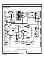
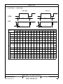
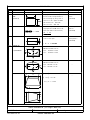
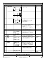
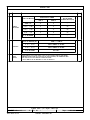
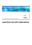
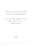
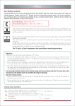
1
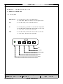
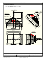
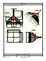
PRODUCT SPEC
PAGE 1 OF 26
REVISION
Originator
Date
Name
New
Eco
*Approval
Rev
No.
Initials
MODEL :
K T-1982*
DESCRIPTION :
MONITOR,PRODUCT
☞19" FST
KT-1 982
☞19" DYNA FLAT
KT-1 982DF
☞19" SHORT NECK
KT-1 982S
☞21" FST
KT-2 182
Initial Release
Name
DRAWN
J.H.LEE
Signature
REVIEWED
APPROVAL
M.B. KIM
DOCUMENT NO :
1982 ******-MS
DIVISION
:
R&D CENTER
Distribution As Above
REV. NO :
1
KTA-0402-02-01
File Quality Procedures By Name
KORTEK CORPORATION
Date
PRODUCT
SPEC
CONTENTS 1. SCOPE --------------------------------------------3
2. RELATED DOCUMENTS --------------------------------- 3 3. EXTERNAL REFERENCE SPEC. -------------------------3 4. REGULATORY INFORMATION ---------------------------4 5. GENERAL CHARACTERISTICS --------------------------5 6. MECHANICAL CHARACTERISTICS -----------------------9 7. ELECTRICAL CHARACTERISTICS ------------------------ 10 8. ADJUSTMENTS --------------------------------------- 15 9. DISPLAY REQUIREMENTS ------------------------------ 18
10. OPERATION OF CIRCUIT ------------------------------ 25
11. PCB INFORMATION ----------------------------------- 28
12. RELIABILITY TEST SPEC. ---------------------------- 30
13. PICTURES ------------------------------------------ 31
KOR TEK CORP. (All Rights Reserved)
DOCUMENT NO : 1982 ******-MS
KTA-0402-02-01
REV. NO : 1
KORTEK CORPORATION
Page
2 Of 26
PRODUCT SPEC
1.SCOPE The monitor described in the followings is based on a 19" diagonal tri-color shadow mask CRT
utilizing an in-line electron gun assembly. This display device is composed of the CRT with deflection yoke,the small PCB containing
the CRT socket and the large PCB containing the deflections,the micom circuits,the power supply
and the video amplifier circuit.
This specification defines a high resolution 19" color monitor to be operated in
analog drive mode input.
2.RELATED DOCUMENTS 2.1 Parts list.
2.2 Service manual
2.3 Product outgoing inspection specification.
2.4 Schematic & waveform of circuit.
2.5 Touch Integration Manual.
3.EXTERNAL REFERENCE SPEC. Refer to 4.REGULATORY INFORMATION. 4.REGULATORY INFORMATION 4.1 SAFETY APPROVAL. The system will be certified according to the following international
safety standards. * UL : UL1950 (be in progress now)
* CSA : CSA C22.2 NO1 (be in progress now)
* CE(LVD) : EN60065 (be in progress now)
* TUV : EN60065 (be in progress now)
* CB : IEC60950 (be in progress now)
4.2. ELECTROMAGNETIC INTERFERENCE.
The system will be certified according to the following international
radiation standards.
* CE(EMC) : EN55022:97 (be in progress now)
* FCC : PART 15 CLASS A VERIFICATION (be in progress now)
4.3 X-RADIATION. The X-radiation emitted from this picture tube will not exceed 0.5mR/h for anode current combination. X-radiation at a constant anode voltage varies linearly with anode current. 4.3.1 The system will comply with the following international standards. * DHHS 21 CFR SUB CH J (be in progress now) K ORTEK COR P. (All Rights Reserved)
DOCUMENT NO : 1982 ******-MS
KTA-0402-02-01
REV. NO : 1
KORTEK CORPORATION
Page
3 Of 26
PRODUCT SPEC
5.GENERAL CHARACTERISTICS 5.1 OPERATION OF CONTROL PART. 5.1.1 Front panel MENU(SELLECT) : In the beginning, starts the OSD controls.
In a sub menu, moves the control to the higher level.
EXIT
: In the main menu, exits the OSD controls.
UP
: In the beginning, proceeds to the contrast adjustment.
In the main menu, moves the control menu to the right.
In a sub menu, increase the adjustment.
DOWN
: In the main menu, moves the control menu to the left.
In a sub menu, decrease the adjustment.
UP
DOWN
MENU(SEL)
EXIT
LED
KORTEK C ORP. (All Rights Reserved)
DOCUMENT NO : 1982 ******-MS
KTA-0402-02-01
REV. NO : 1
KORTEK CORPORATION
Page
4 Of 26
PRODUCT SPEC
5.3 CRT SPEC. & DIMENSION. 5.3.1 CRT DIMENSION.(samsung) : KT-1982F 29.1±0.7
Cavity cap
Contact area of
external conductive
coating
90°
95.0 MIN
417.2 ±6.5
261.5 ±2.8
156.5 ± 2. 8
Red silicon
insulating coating
494.8±2.4
180 MAX
413.2±2.4
80.0 ±0.7
34
20. 0 MAX
2
408.02±2.0
Shrinkage band
365.80MIN
・
327 6 ±2.4
・
322 66±2.0
274 3 MIN
R G B
・
457.21MIN
KORTE K CORP. (All Rights Reserved)
DOCUMENT NO : 1982 ******-MS
KTA-0402-02-01
REV. NO : 1
KORTEK CORPORATION
Page
5 Of 26
PRODUCT SPEC
5.3.2. CRT DIMENSION.(SAMSUNG DYNAFLAT): KT-1982D
29.1±0.7
Cavity cap
Contact area of
external conductive
coating
90°
95. 0 MIN
418. 5 ±4.5
263.8 ±2.8
158.8 ±2.0
Red silicon
insulating coating
494.8±2.0
180 MAX
413.2±2.0
80.0 ±0.7
34
20.0 MAX
2
408.02±2.0
Shrinkage band
365.80MIN
・
327 6 ±2.0
・
322 66±2.0
274 3 MIN
R G B
・
457.2 Min
KORTEK CO RP. (All Rights Reserved)
DOCUMENT NO : 1982 ******-MS
KTA-0402-02-01
REV. NO : 1
KORTEK CORPORATION
Page
6 Of 26
PRODUCT SPEC
5.3.3. CRT DIMENSION.(SAMSUNG SHORT NECK): KT-1982S
29 .1±0 .7
Ca vity cap
148 8 ±2 8
Red sil icon
ins ulat ing coat ing
・
C ontac t ar ea o f
e xtern al c ondu ctiv e
c oatin g
233 8 ±2 8
・
・
・
100 °
374 37 ±4 5
・
70 0 MIN
・
・
49 4.8± 2.0
20.0 MAX
2
80.0 ±0.7
34
18 0 MA X
41 3.2± 2.0
40 8.0± 2.0
Sh rinka ge b and
3 65.80 MIN
・
・
327 6 ±2.0
B
322 7 ±2.0
G
274 3 MIN
R
・
4 57.2 1MIN
KORTEK CO RP. (All Rights Reserved)
DOCUMENT NO : 1982 ******-MS
KTA-0402-02-01
REV. NO : 1
KORTEK CORPORATION
Page
7 Of 26
PRODUCT SPEC
5.4 SIGNAL CABLE & CONNECTION. 5.4.1 Signal cable A shield signal interface cable must be intended as a part of the monitor. The cable length shall be 1800 mm with a tolerance of ±50mm . This cable shall be of a suitable type in order to comply with any specification item , and shall be terminated in a 15 pin D-shell male connector type FOXCONN D973292-8 or equivalent,with pin assignment as follows. 5.4.2 SIGNAL CABLE PIN CONNECTION (15 PIN D-SUB MINIATURE SIGNAL CONNECTOR WITH CABLE)
CONNECTION
D-SUB 15PIN
IBM PC
WIRE COLOR
6P CONN 6P CONN
1
RED
RED COAX-IN
6P CONN-1
2
GREEN
GREEN COAX-IN
6P CONN-3
3
BLUE
BLUE COAX-IN
6P CONN-5
4
N.C
-
-
5
GND
BLACK COAX-GND
6
RED-GND
RED COAX-GND
6P CONN-2
7
GREEN-GND
GREEN COAX-GND
6P CONN-4
8
BLUE-GND
BLUE COAX-GND
6P CONN-6
9
N.C
-
-
10
ID
GRAY
6P CONN-3
11
N.C
-
-
12
SDA
YELLOW
6P CONN-5
13
H-SYNC
ORANGE
6P CONN-1
14
V-SYNC
WHITE
6P CONN-2
15
SCL
RED
6P CONN-4
SHELL
GND
BLACK
6P CONN-6
REMARK
5.4.3 BUYER CONNECTOR PIN CONNECTION ( OPTION )
KORTEK CORP. (All Rights Reserved)
DOCUMENT NO : 1982 ******-MS
KTA-0402-02-01
REV. NO : 1
KORTEK CORPORATION
Page 8 Of 26
PRODUCT SPEC
6.MECHANICAL CHARACTERISTICS. 6.1 PRODUCT DIMENSION.(unit : mm) Description
With stand
Packaging
Width
500
430
Height
405
550
Length
490
460
6.2 WEIGHT : NET
kg
GROSS
kg
6.3 MECHANICAL MATERIALS. 6.3.1 INTERNAL METAL PARTS. * PCB GUIDE CHASSIS DIMENSION
REV. NO
DATE
ECO NO
DESCRIPTION OF CHANGE
DRAWN
APPROVAL
248
75
75
50
1
6 1111 20
%%c4
248
75
12
9
5
3
164
%%c2.5
4
1
7
2
7
4
8
1
4
1
1
7
1
1
8
4
%%c2.5 5
4
9
6
7
12
3
%%c4
2
2
4
7
7
9
4
1
%%c3
3
4
5
36
24 4124
87
4124
34
61
4 22
4
124
4 22 4
30
248
0
248
12
65
2
95
0
8
9
12
9
0
248
64
1
9
%%c4
20 22.5
6
9
0
9
9
APPROVALS DATE
KORTEK CORPORATION
UNLESS OTHERWISE
DRAWN
TITLE
2
PRESS:APPLY TO KSB-0413( )
9
MOLD:APPLY TO ( ) RESIN
BY DIN 16901
REVIEWED
APPROVAL
REV.NO
REF
9
2
CUSHION:APPLY TO KSA-1513
9
9
6
248
0
151
9
3
HOLE 7x3
48.5
OTHER
DWG.NO
THILRD ANGLE PROJECTION
SHEET
MATERIAL SCALE
UNIT
SHEET
0
Q'TY
(주) 코
텍
.
KORTEK C ORP. (All Rights Reserved)
REV. NO : 1
Page
9
Of 26
8
8
KORTEK CORPORATION
8
3
8
KTA-0402-02-01
.
2
DOCUMENT NO : 1982 ******-MS
4
0
0
2
4
PRODUCT SPEC
6.3.1 FRAME METAL PARTS.(BUYER OPTION) FRONT ( STANDARD FRAME )
* MAIN FRAME CHASSIS ( STANDARD )
.
5
.
APPROVAL
0
6
.
5
.
REV. NO DATE ECO NO DESCRIPTION OF CHANGE DRAWN
428
27
374
27
2.5
±0
.20
40±5.00
2.5¡
.2
0
275
390±
0
5.0
6±
0.20
295
10
1 ±5
8 ±0
3 ±5
275
3 ±5
10
±
120
0
5.0
358±5.00
APPROVALS
DATE
KORTEK CORPORATION
UNLESS OTHERWISE
DRAWN
PRESS:APPLY TO KSB-0413( )
MOLD:APPLY TO ( ) RESIN
TITLE
REVIEWED
BY DIN 16901
APPROVAL
REV.NO
REF
CUSHION:APPLY TO KSA-1513
OTHER
THILRD ANGLE PROJECTION
DWG.NO
Q'TY
(주) 코
KTA-0503-00-01
SHEET
MATERIAL
SCALE
텍
KORTEK C ORP. (All Rights Reserved)
DOCUMENT NO : 1982 ******-MS
KTA-0402-02-01
REV. NO : 1
KORTEK CORPORATION
Page
10
Of 26
UNIT
SHEET
PRODUCT SPEC
7.ELECTRICAL CHARACTERSISTICS.
7.1 BLOCK DIAGRAM
AC
INLET
SOCKET
S WIT CH ING
IC ( K S1 265 )
5V
6.3V
12V
14V
-14V
80V
220V
SWITCHING
MODE
LINE
FILTER
DEGAUSSING
BRIDGE
DIODE
H/V SYNC
INPUT
SUPPLY
FEEDBACK
CONTROL
DPMS OUTPUT
- SUSPEND
- OFF
LED
CONTROL
POWER
MICRO
CONTROL LER
I² C
TLIT
CONTROL
TILT COIL
VERTICAL
OUTPUT
( KA2142 )
SYNC
PROCESSOR
( TDA9113 )
VIDEO AMP
( KA2506 )
OSD
PROCESSOR
( WT6802 )
I² C
UNIT
HORIZONTAL
( WT62P1 )
DRIVE
CIRCUIT
ADJUST
KEY
TLIT
SIGNAL
INPUT
VIDEO
OUTPUT
(LM2405 )
CRT
CUT-OFF
CONTROL
I² C
DEFLECTION YOKE
-HIGH
VOLTAGE
-H.FOCUS
-V.FOCUS
-SCREEN
FLYBACK
OUTPUT STAGE
DEFLECTION
TRANS
S-CORRECTION
CIRCUIT
(S1~
S4)
DDC 2BI
- H/V SIZE
- H/V POSI
- S-PIN
- TRAP
- PARA
- PIN BAL
- ACL
- TILT
- DEG
HIGH VOLTAGE
PROTECTION CIRCUIT
BRIGHT
CONTROL
HIGH VOLTAGE
DRIVE CIRCUIT
HIGH VOLTAGE
OUTPUT STAGE
HIGH VOLTAGE
REGULATION
KORTEK CORP.. (All Rights Reserved)
DOCUMENT NO : 1982 ******-MS
KTA-0402-02-01
DYNAMIC
FOCUS
CIRCUIT
REV. NO : 1
Page : 11 Of 26
KORTEK CORPORATION
PRODUCT SPEC
7.2 INPUT POWER. The display device shall maintain the specified performances in the range described below. DESCRIPTION
NOMINAL
REMARKS
NO
1
Power Source
AC 90V ~264V
Universal Power
2
Frequency
47.5 ~63Hz
3
Power Consumption
MAX. 100W
7.3 SIGNAL & SYNS.TIMING The input signals shall be applied to the display device through the signal cable which must be intended as part of the monitor. SECTION
DESCRIPTION
NOMINAL
REMARKS
VIDEO SIGNAL
RED
GREEN
BLUE
VIDEO INPUT
0.0 to 0.714Vp-p ANALOG
POLARITY
POSITIVE
PIXEL RATE
MAX. 120MHz
MAX. RESOLUTION
1024 × 768 / 100Hz
INPUT IMPEDANCE
75 ohms
TYPE
POLARITY
SYNC SIGNAL
FREQUENCY
LEVEL
SEPARATE H/V
COMPOSITE H/V
POSITIVE OR NEGATIVE
HOR.: 30 ~ 81KHz
VER.: 50 ~ 160 Hz
SEPARATE SYNC
: HIGH ≥2.0V, LOW ≤0.8V
KORT EK CORP. (All Rights Reserved)
DOCUMENT NO : 1982 ******-MS
KTA-0402-02-01
REV. NO : 1
KORTEK CORPORATION
Page
12 Of 26
PRODUCT SPEC
7.4 TIMING CHART ( FACTORY MODE ) HORIZONTAL
VERTICAL
VIDEO
C
D
E
Q
R
S
SYNC
B
P
A
O
I.B.M
DESCRPTION
720*400
VESA
640*480
1024*768
640*480
800*600
800*600
800*600
1024*768
800*600
1024*768
1024*768 1280*1024
1024*768 1280*1024 1024*768
60.241
63.702
68.677
79.976
81.400
(I)
H
f KHz
31.469
31.469
35.52
37.860
37.88
46.875
48.077
48.363
53.674
56.476
A
uS
31.778
31.778
28.15
26.413
26.40
21.333
20.800
20.677
18.631
17.707
15.698
14.561
12.504
12.285
B
uS
3.813
3.813
3.92
1.270
3.20
1.616
2.400
2.092
1.138
1.813
1.358
1.016
1.067
0.988
C
uS
1.907
1.907
1.25
4.603
2.20
3.232
1.280
2.262
2.702
1.920
1.812
2.201
1.837
1.624
D
uS
25.422
25.422
22.80
20.317
20.00
16.162
16.000
15.754
14.222
13.653
12.075
10.836
9.481
9.037
E
uS
0.636
0.636
0.18
0.762
1.00
0.323
1.120
0.369
0.569
0.320
0.453
0.508
0.119
0.635
NEG
NEG
POS
POS
POS
POS
POS
NEG
POS
NEG
NEG
POS
NEG
POS
60.00
84.997
75.025
100.00
POL.
V
f
Hz
70.087
59.940
86.906
72.809
60.317
75Hz
72.188
60.00
85.061
70.00
O
mS
14.268
16.683
11.50
13.735
16.58
13.333
13.853
16.667
11.756
14.272
16.640
11.765
13.329
10.000
P
mS
0.064
0.064
0.113
0.079
0.11
0.064
0.125
0.124
0.056
0.106
0.047
0.044
0.038
0.037
Q
mS
1.080
1.048
0.563
0.740
0.61
0.448
0.478
0.60
0.503
0.513
0.471
0.524
0.475
0.516
R
mS
12.711
15.253
10.81
12.678
15.84
12.8
12.480
15.88
11.179
13.599
16.075
11.183
12.804
9.435
S
mS
0.413
0.318
0.014
0.238
0.03
0.021
0.770
0.062
0.019
0.053
0.047
0.015
0.013
0.012
POS
NEG
POS
POS
POS
POS
POS
NEG
POS
NEG
NEG
POS
POS
POS
POL.
75Hz
KORTEK C ORP. (All Rights Reserved)
DOCUMENT NO : 1982 ******-MS
KTA-0402-02-01
REV. NO : 1
KORTEK CORPORATION
Page
13 Of 26
PRODUCT SPEC
8.ADJUSTMENTS 8.1 DEFLECTION CIRCUIT ADJUSTMENT 8.1.1 Screen position adjustment. (H-SHIFT,V-SHIFT)
* Receive a cross-hatch pattern signal of all factory preset mode.
* Adjust H-SHIFT,V-SHIFT for the screen position to center.
※ NOTE : All of the user control functions are adjustable when the OSD
appears on the screen. 8.1.2 Horizontal size adjustment. (H-SIZE)
* Adjust contrast and brightness controls to maximum.
* Receive a cross-hatch pattern signal of all modes. * Adjust H-SIZE for the horizontal size equal to 400±3.0 mm.
8.1.3 Vertical size adjustment. (V-SIZE)
* Adjust contrast and brightness controls to maximum .
* Receive a cross-hatch pattern signal of all modes. * Adjust V-SIZE for the vertical size equal to 295±3.0 mm.
8.1.4 Pincushion adjustment. (Pincushion)
* Receive a cross-hatch pattern signal of all modes. * Adjust Pincushion for compensation of the east/west distortion.
8.1.5 Trapezoidal adjustment
* Receive a cross-hatch pattern signal of all modes. * Adjust TRAPEZOIDAL for compensation of the geometric distortion..
8.1.6 Parallelogram adjustment
* Receive a cross-hatch pattern signal of all modes. * Adjust PARALLELOGRAM for compensation of the geometric distortion.
8.1.7 Pin Balance adjustment
*Receive a cross-hatch pattern signal of all modes.
*Adjust PIN BALANCE for compensation of the geometric distortion.
KORTEK C ORP. (All Rights Reserved)
DOCUMENT NO : 1982 ******-MS
KTA-0402-02-01
REV. NO : 1
KORTEK CORPORATION
Page
14 Of 26
PRODUCT SPEC
8.1.8 Tilt(Rotation) Adjustment
*Receive a cross-hatch pattern signal of all modes
*Adjust tilt(Rotation) for compensation of the geometric distortion.
8.2 VIDEO CIRCUIT ADJUSTMENT.
8.2.1 Control function.
* Contrast control
This function controls the contrast of the screen, and determines the gain of the video
amplifier.
* R,G,B-GAIN controls.
These controls are used for adjusting the gain of RED,GREEN,BLUE video signals.
* R,G,B-BIAS controls.
These controls are used for adjusting the RED,GREEN,BLUE bias-voltage of Cathode.
* Focus control. (On the FBT)
This controls determines the optimum focus of the screen.
8.3 THE ADJUSTMENT OF WHITE BALANCE.
* Adjust the screen V/R control slowly so that voltage of G2 is equal to 580 ~600 volt.
* Operate the monitor for 15 minutes in order to warm up the CRT and circuits.
* Degauss the CRT face fully with degaussing tool.
* Adjust brightness and contrast to the 80% value.
* Receive a raster pattern of 800*600 48KHz,60Hz mode.
* Adjust R,G,B-BIAS controls so that the raster becomes white and luminance is
0.5(F/L) and for the specified color coordinate.
* Receive a one ball white pattern of 800*600 48KHz,60Hz mode.
* Adjust R,G,B-GAIN controls for the specified white color with the color analyzer.
* Receive a full white screen of 800*600 48KHz,60Hz mode.
* Adjust ACL controls for the specified luminance with the color analyzer.
KO RTEK CORP . (All Rights Reserved)
DOCUMENT NO : 1982 ******-MS
KTA-0402-02-01
REV. NO : 1
KORTEK CORPORATION
Page
15 Of 26
PRODUCT SPEC
◆ SPECIFICATIONS.
※ Standard color coordinate.(BRT,CONT; 80%)
* 6500 °K ; X=0.313 ± 0.02
Y=0.329 ± 0.02
* 9300 。K ; X=0.281 ± 0.02
Y=0.311 ± 0.02
※ Maximum brightness : BRT,CONT ;80%
・With full white pattern ; 25 ~ 30 F/L (9300&6500。K) ☞ BUYER OPTION
・With one ball white pattern ; 50 ~ 60 F/L (9300&6500。K) ☞ BUYER OPTION
・Checking area : Center of display.
9.DISPLAY REQUIREMENTS 9.1 Engineering check and test equipment 9.1.1 Engineering check This specification defines a high resolution 19" color monitor to be operated in analog drive mode.
This procedure defines test & inspection requirements, and acceptance criteria for visual and functional characteristics.
9.1.2 Test equipment. 1.Personal computer or signal generator, test program(software) for color monitor.
2.Color-Analyzer (CA-100).
3.Display template for screen adjustment.
9.2 Engineering check point. 9.2.1 Packaging.
Check the packaging to make sure the unit is in a shippable condition. The following items shall be verified.
* BOX.
* LABEL
9.2.2 Enclosure The monitor,intended as a finished product,shall comply with any ergonomic and safety specification contained in box.
K ORTEK CO RP. (All Rights Reserved)
DOCUMENT NO : 1982 ******-MS
KTA-0402-02-01
REV. NO : 1
KORTEK CORPORATION
Page
16 Of 26
PRODUCT SPEC
NO
ITEM
1
1-1
SPECIFICATION
REQUIREMENT
VISUAL
Pattern
Standard direction : N/E (all items)
DISPLAY
400㎜
SIZE
(Standard)
A.Display the cross hatch pattern.
Cross-
B.The size must be adjustable to
hatch
the followings by using user's
295㎜
(640/60Hz)
control for all specified mode.
* Horizontal size : 400±3㎜.
* Vertical size : 295±3㎜ .
1-2
LINEARITY
Linearity
A.The linearity of screen must be
Lmax-Lmin
× 100%
Lmax+Lmin
16×12 square
displayed on the CRT within the
pattern
spec.(Horizontal and vertical)
(640/60Hz)
* Ver : ≤ 5%
Hor : ≤ 5%
1-3
TILT
A.The tilt must be within the
Cross-
limit of the spec.
hatch pattern
(640/60Hz)
A
* A = ± 1.3mm MAX.
1-4
DISTORTION
1)PINCUSHION
C
* Maximum allowable error;
A
B
D
A,B
: Lessthan 2.0 mm
C,D
: Lessthan 2.0 mm
"
2)BARREL
* Maximum allowable error;
C
A
B
a
A
"
C,D : Lessthan 1.5 mm
D
3)TRAPEZOID
A,B : Lessthan 1.0 mm
* ┃ A-B ┃ ≤2.0 mm
b
"
* ┃ C-D ┃ ≤2.5 mm
* a,b,c,d ≤ 2.5 mm
B
c
D
C
d
KORTEK CORPOR ATION. (All Rights Reserved)
DOCUMENT NO : 1982 ******-MS
KTA-0402-02-01
REV. NO : 1
KORTEK CORPORATION
Page
17 Of 26
PRODUCT SPEC
NO
1-4
ITEM
SPECIFICATION
REQUIREMENT
Pattern
4)PARALLELOGRAM
Cross* A,B ≤ 2.0 mm
hatch
(640/60Hz)
B
A
5)"S"
CURVE
A
* A ≤ 2.0 mm
"
1-5
DISPLAY-CENTER
* ┃ A-B ┃ ≤6 mm
C
* ┃ C-D ┃ ≤4 mm
A
B
"
* The maximum variation of the
display center have to be
within the spec.
D
1-6
FOCUS
* Visual test
* Cut off the back raster. (0.07F/L)
* Adjust contrast maximum or 47F/L
at one ball white pattern.
* Change pattern to "windows-me
pattern".
* Check the focus of the dots,bars,
and characters.
1-7
JITTERING
* Visual test
* There shall be no jitter when the
screen is viewed from 45 Cm
1-8
MIS CONVER-GENCE
* A zone(Φ295mm
circle):0.25mm MAX
* B zone
:0.35 mm max.
* Measure the distance between red,
green and blue lines with a microscope after the proper adjustment
of white balance.
1-9
ACOUSTIC
NOISE
* Not any audible
sound
* During the display operating, it
has not to be any audible sound.
1-10
WHITE
BALANCE
* 6500。K
X=0.313
Y=0.329
* 9300。K
X=0.281
Y=0.311
* The white color coordinates in the
center of the surface of CRT after
proper adjustment of white balance
± 0.02
± 0.02
Windows-me pattern
(640/60Hz)
Cross-hatch
"
Full white
pattern
(0.7V Level)
* Cont; 80% (DEFULT VALUE)
± 0.02
± 0.02
1-11
WHITE
COLOR
TRACKING
* 6500。K
X = 0.313±0.02
Y = 0.329±0.02
* 9300。K
X = 0.281±0.02
Y = 0.311±0.02
* 10 F/L and MAX
1-12
PURITY
* Visual test
* After degaussing,it has not to be
any perceptible color shift in the
scanning area while viewing a
primary color field at 30 cm's
distance.
R,G,B
Primary
color
pattern
1-13
RASTER
REGULATION
* Less than 1.5 mm
at one side
* Measure it from minimum to maximum
luminance at full white screen.
Full white
pattern
(640/60Hz)
* Set contrast control at 10 and MAX
* Measure it in the center of CRT.
* No one color shall achieve dominance,when the standard white color
is displayed at all the allowed
settings of the contrast control.
"
KORT EK CORP. (All Rights Reserved)
DOCUMENT NO : 1982 ******-MS
KTA-0402-02-01
REV. NO : 1
KORTEK CORPORATION
Page
18 Of
26
PRODUCT SPEC
NO
ITEM
1-14
BRIGHTNESS
UNIFORMITY
1-15
WHITE
UNIFORMITY
SPECIFICATION
REQUIREMENT
* More than 75%
Pattern
* Measure it at center contrast
to 25 F/L,BRT : cut-off
* BRT ; max
CONT ; max.
* COLOR MODE ; 9300。K
* The X or Y coordinate between any
position in the entire display
area shall not vary more than 0.015
* X of L1,L2,L3,L4 ≤ X of L0±0.015
Y of L1,L2,L3,L4 ≤ Y of L0±0.015
L2
L1
L0
L3
Full white
pattern
L4
"
1-16
MOIRE
* Visual test
* No any visible moire at 20F/L, "A"Zone
(ψ230mm circle)
* Full white pattern (1024×768/60Hz)
Full white
pattern
1-17
MODE CHANGE
* Visual test
* Upon changing modes,the display
image must be stable and meet all
image performance specifications
within 1.0 second.
* Mute time must be longer than the
input signal recognition time.
all modes
1-18
LUMINANCE
* FULL WHITE PATTERN
: 25 ~ 27 F/L
* ONE BALL WHITE
; 45 ~ 65 F/L
* MINIMUM LUMINANCE
: LESS THAN 3F/L
Full white
pattern
(1024 X768/60Hz)
* CONTRAST : MAX
* 9300。K,6500。K
* MINIMUM LUMINANCE : CONTRAST : MIN.
BRIGHTNESS : MIN.
1-19
GRAY SCALE
LINEARITY
* VISUAL TEST
*CONTRAST : MAX.
;The 16 step gray bars shall be
distinguishable.
*CONTRAST : MAX.
;More than 15 step gray bars
are distinguishable.
16 gray
pattern
(1024 X 768/60Hz)
1-20
RASTER
LUMINANCE
* 0.5 F/L
(BUYER OPTION)
* CONTRAST ; MAX.
* 6500°K; X=0.313
Y=0.329
* 9300°K; X=0.281
Y=0.311
1024 ×768/60Hz
1-21
DYNAMIC
REGULATION
* LESS THAN 1.0mm
ONE SIDE
*CONTRAST:MAX.
*USE HORIZONTAL BAR PATTERN
1-22
SIZE CONTROL
RANGE
* HORIZONTAL : LESS THAN 310mm,MORE THAN OVER SCAN
* VERTICAL : LESS THAN 215mm,MORE THAN OVER SCAN
1-23
TOTAL
DISTORTION
A
B
A,B ≤2.5 mm
±
±
±
±
0.02
0.02
0.02
0.02
1024 ×768/60Hz
CROSS-HATCH
(1024/60Hz)
* In case of factory preset mode,the
image performance meets
specification without user
adjustments.
* In case of user mode,the image
performance meets the
specifications with user
adjustments.
CROSSHATCH
(1024X768/60Hz)
1-24
BENT ON TOP
LESS THAN 0.5mm
CROSS-HATCH
(1024/60Hz)
1-25
SPOT
VISUAL TEST
*No any visible spot at power-off
*No any visible spot at mode change
"
1-26
RINGING
VISUAL TEST
*Ringing, vertical black bar shall
not be visible to the eye when
viewed at 50cm from CRT surface
and video is positioned center.
FULL
WHITE
(1024/60Hz)
1-27
OSD
VISUAL TEST
Color&Positio
n
*No discolor
*In case of factory preset mode, OSD
display
is located at just center position.
All modes
1-28
OSD NOISE&
distorion
*No visible OSD distortion &Noise
All modes
VISUAL TEST
KORTEK CORP. (All Rights Reserved)
DOCUMENT NO : 1982 ******-MS
KTA-0402-02-01
REV. NO : 1
KORTEK CORPORATION
Page
19 Of 26
PRODUCT SPEC
9.2.4 CRT SPECIFICATIONS
NO
ITEM
SPECIFICATION
RMK.
ALLOWABLE NUMBER
OF BLEMISH
BLEMISH
ZONE A
ZONE B
TOTAL
ZONE A
ZONE B
ZONE A+B
1TRIO
1
1
1
--
--
50
A
0
2
2
--
50
--
B
1
2
2
--
50
50
3
3
--
--
--
--
--
--
HIGH
1.
CONTRAST
BLEMISHES
ALLOWABLE MINIMUM
SEPARATION
G
5
1DOT
8
R,B
5
5
LESS THAN
8
IGNORE
------
(A) 2 CONSECUTIVE SAME COLOR PHOSPHOR DOTS
(B) 2 CONSECUTIVE DIFFERENT COLOR PHOSOPHOR DOTS
*ZONE A : DISPLAY AREA (400 mm X 295 mm )
*ZONE B : OTHER AREA
ALLOWABLE NUMBER
OF BLEMISH
BLEMISH
MEDIUM
2.
CONTRAST
BLEMISHES
ALLOWABLE MINIMUM
SEPARATION
ZONE A
ZONE B
TOTAL
ZONE A
ZONE B
ZONE A+B
3 CONSECUTIVE DOTS
1
2
2
--
30
30
2 CONSECUTIVE DOTS
2
5
5
30
20
20
1 DOT
IGNORE
IGNORE
IGNORE
--
--
--
*MINIMUM SEPARATION IS 20mm AMONG HIGH AND MEDIUM CONTRAST BLEMISHES.
(EXCLUDING 1 DOT MEDIUM CONTRAST BLEMISHES)
LOW
3.
BLEMISHES
IN ZONE A
EQUIVALENT DIAMETER OF THE TOTAL AREA OF LOW-CONTRAST
BLEMISHES SHOULD BE LESS THAN 13 mm.
BLEMISHES
IN ZONE B
EQUIVALENT DIAMETER OF THE TOTAL AREA OF LOW-CONTRAST
BLEMISHES SHOULD BE LESS THAN 50 mm.
CONTRAST
BLEMISHES
KOR TEK CORP. (All Rights Reserved)
DOCUMENT NO : 1982 ******-MS
KTA-0402-02-01
REV. NO : 1
KORTEK CORPORATION
Page 20 Of 26
PRODUCT SPEC
NO
ITEM
SPECIFICATION
RMK
PERMISSIBLES NUMBER
SIZE OF DEFECTS
4.
5.
6.
BUBBLES
AND STONES
SCRATCHES
OTHER
DEFECTS
MIN.DISTANCE
BETWEEN DEFECTS(mm)
ZONE A
ZONE B
OVER 0.91
0
0
--
0.76 ~ 0.90
0
2
57
0.51 ~ 0.75
1
3
57
0.25 ~ 0.5
3
6
57
0.24 OR UNDER
--
--
--
SIZE OF DEFECTS(mm)
ZONE A + ZONE B
0.14 ~ 0.20
TOTAL LENGTH 19 mm MAX.
0.06 ~ 0.13
TOTAL LENGTH 50 mm MAX.
0.05 OR UNDER
NO LIMIT.
OTHER DEFECTS NOT STATED ABOVE (SUCH AS CHIPS,CRACKS,BRUISES,SHAR MARKS,
EMBEDDED STONES,STRAINS,CLOUDS AND POLISHED PATTERNS) ARE PERMMITED WHEN
THEY ARE NOT VISIBLE FROM THE VIEWING DISTANCE.
LIMITS SAMPLES MAY BE REFFERED IN CASE OF NECESSITY.
KORTEK C ORP. (All Rights Reserved)
DOCUMENT NO : 1982 ******-MS
KTA-0402-02-01
REV. NO : 1
KORTEK CORPORATION
Page
21 Of
26
PRODUCT SPEC
10.OPERATION OF CIRCUIT 10.1 POWER CIRCUIT.
The switching mode power supply is adopted for universal power supply. The chassis (secondary side) is isolated from the power source (primary side) by the transformer T101.
By the winding of the transformer T101 connected to the drain of IC106 and the other winding connected to the control circuit, the IC106 is submitted to feed back by sync trans T102.
When the voltage of power source or load current is varied, it is detected by T102
and the voltage is applied to PIN 3 of IC106. When the voltage applied to PIN 3 is varied,the conducting time of IC106 is varied
to compensate output voltage for the change, which makes output voltage of T101 stabilized. 10.2 DPMS CIRCUIT 10.2.1 SUSPEND MODE If the H or V sync input is inactive, the output of IC501 pin14 becomes high, and the
output voltage of IC103 will be down.
Therefore the deflection circuit and the video amp circuit can not operate.
At this suspend mode, the LED on the front of this unit indicates Blinking.
The power consumption at suspend mode is less than 15W.
10.3 Interface circuit
This is composed of IC501. IC101 circuit detects frequency and polarity and controls the displayed image.
IC101 performs functions as follows.
※ DPMS function
※ VIDEO MODE selection
※ G/D correction control
※ OSD control
※ IMAGE SIZE,POSITION CONTROL
※ IMAGE DATA MEMORY.
KORTEK C ORP. (All Rights Reserved)
DOCUMENT NO : 1982 ******-MS
KTA-0402-02-01
REV. NO : 1
KORTEK CORPORATION
Page
22 Of 26
PRODUCT SPEC
10.4 VIDEO DRIVE CIRCUIT. The R, G and B input signals with analog level are applied to the pre-amplifier KA2506.
This section amplifies the output signal of a generator enough to drive a video
output circuit and video of OSD buffering.
Video gain is controlled by the DC voltage of PIN 12. Clamping pulse is applied to PIN 18 of IC201.(BACK PORCH CLAMP) 10.5 VIDEO OUTPUT CIRCUIT.
The pre-amplified R, G and B video signals are applied to the amplifier IC803(LM2405)
And then, these video signals are drived to the cathodes of CRT.
The CRT bias for accurate white balance is obtained by R, G and B bias controls circuit.
That circuit composed IC803. 10.6 DEFLECTION CIRCUIT.
This circuit has two ICs. IC301(TDA9113) is a monolithic IC for horizontal and vertical
sync. processing. And IC201 is a monolithic IC for vertical power amplifier.
10.6.1 Vertical Deflection Circuit.
The vertical sync signal is applied to PIN 13,23 of IC301.
The vertical frequency of the oscillator can be varied by the RC constant at PIN 6,8.
Vertical screen size can be controlled by the current at PIN 13 of IC301.
IC201 is the vertical power amplifier that drives vertical DY.
10.6.2 Horizontal Deflection Circuit. The horizontal sync signal is applied to PIN 1 of IC301. The IC301 has the autosync detection function of frequency-locked loop that can
look the H-oscillator over a wide frequency range.
※ Trapezium (by DC voltage applied at pin11)
※ Side-pin (by DC voltage applied at pin11)
※ H-size (by DC voltage applied at pin11)
KORTEK C ORP. (All Rights Reserved)
DOCUMENT NO : 1982 ******-MS
KTA-0402-02-01
REV. NO : 1
KORTEK CORPORATION
Page
23 Of 26
PRODUCT SPEC
11.PCB INFORMATION 11.1 MAIN PCB
: MJ19FS3D82
11.2 SOCKET PCB
:
SM1982F1DO
12.RELIABILITY TEST SPEC. 12.1 Environmental Test
The monitor unit must not be degradiated and damaged by operating over the specified
range and will meet specifications when returned to the operating environment. KORTEK will perform these tests on the monitor prior to its release.
The monitor is required to pass these tests before mass production.
These tests are detailed in KORTEK environment specification. 12.2 Temperature test
* Operating : 0℃ To 45℃ * Storage
: -20℃ To +60 ℃ 12.3 Humidity test * Operating : 15% To 80% (Non condensing) * Storage : Maximum 90% 12.4 Drop test : Refer to KORTEK's ENVIRONMENTAL TESTS MANUAL. 12.5 Leakage current test : Refer to KORTEK's ENVIRONMENTAL TESTS MANUAL. 12.6 ESD test : Refer to KORTEK's ENVIRONMENTAL TESTS MANUAL.
12.7 Long life test.(MTBF) The monitor shall have 50,000hrs MTBF when operated under any combination of conditions as detailed specification. 12.8. Altitude. * Operating : 0 ~10,000 ft * Non operating : 0 ~15,000 ft KORTEK C ORP. (All Rights Reserved)
DOCUMENT NO : 1982 ******-MS
KTA-0402-02-01
REV. NO : 1
KORTEK CORPORATION
Page
24
Of 26
PRODUCT SPEC
13.PICTURES. 13-1. PCB ASS'Y 13-2. PCB & GUIDEE CHASSIS ASS'Y
KORTEK C ORP. (All Rights Reserved)
DOCUMENT NO : 1982 ******-MS
KTA-0402-02-01
REV. NO : 1
KORTEK CORPORATION
Page
25 Of 26
PRODUCT SPEC
13-3. FRONT ( STANDARD FRAME ) 13-4. REAR ( STANDARD FRAME )
KORTEK C ORP. (All Rights Reserved)
DOCUMENT NO : 1982 ******-MS
KTA-0402-02-01
REV. NO : 1
KORTEK CORPORATION
Page
26 Of 26