1
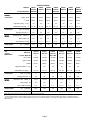
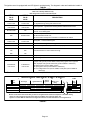
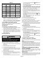
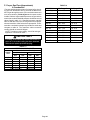
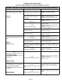
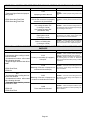
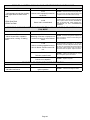
TABLE 11
PROVE SWITCH SET POINTS
−1 to −14
Units
0 − 4500ft
(0 − 1372m)
4501’ − 7500’
1373m − 7500m
7501’ − 10,000’
(2287 − 3048m)
−045
0.47"
(116Pa)
0.36" (89Pa)
0.36" (89Pa)
−070
0.47"
(116Pa)
0.36" (89Pa)
0.36" (89Pa)
−090
0.51"
(126Pa)
0.47" (116Pa)
0.43" (106Pa)
−110
0.58" (.14Pa)
0.47" (116Pa)
0.43" (106Pa)
−135
0.51"
(126Pa)
0.47" (116Pa)
0.43" (106Pa)
−155
0.51"
(126Pa)
0.47 (116a)
0.43" (106Pa)
All −15 and
later models
0.40" (99pa)
no change
0.36" (89Pa)
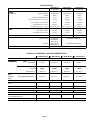
NOTE−− −1 to −14 units require a high altitude prove
switch kit if installed above 4500 ft (1370 m).
NOTE−− −15 and later units require a high altitude
prove switch kit if installed above 7500 ft (2286 m).
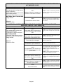
II−PLACEMENT AND INSTALLATION
Make sure unit is installed in accordance with installation
instructions and applicable codes.
III−START-UP
A−Preliminary and Seasonal Checks
1 − Inspect electrical wiring, both field and factory installed
for loose connections. Tighten as required.
2 − Check voltage at disconnect switch. Voltage must be
within range listed on the nameplate. If not, consult the
power company and have voltage condition corrected
before starting unit.
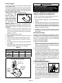
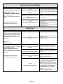
B−Heating Start-Up
WARNING
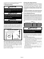
Turn knob on gas valve clockwise
to OFF. Do not
force. See figure 18.
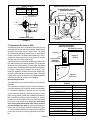
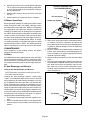
White Rodgers 36E/36F Gas Valve − Move gas valve
switch to OFF position.
7 − Wait five minutes to clear out any gas. If you then smell
gas, STOP! Immediately call your gas supplier from a
neighbor’s phone. Follow the gas supplier’s instructions. If you do not smell gas go to next step.
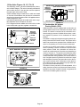
8 − Honeywell VR8205 Gas Valve with On/Off Switch −
Move gas valve switch to ON position. Do not force.
See figure 17.
Honeywell VR8205 Gas Valve with Control Knob −
Turn knob on gas valve counterclockwise
to ON.
Do not force.
White Rodgers 36E/36F Gas Valve − Move gas valve
switch to ON position.
9 − Replace the upper access panel.
10− Turn on all electrical power to to the unit.
11− Set the thermostat to desired setting.
NOTE − When unit is initially started, steps 1 through 11
may need to be repeated to purge air from gas line.
12− If the appliance will not operate, follow the instructions
Turning Off Gas to Unit" and call your service technician or gas supplier.
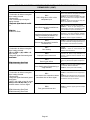
Turning Off Gas to Unit
1 − Set the thermostat to the lowest setting.
2 − Turn off all electrical power to the unit if service is to be
performed.
3 − Remove the upper access panel.
4 − Honeywell VR8205 Gas Valve with On/Off Switch −
Move gas valve switch to OFF position. Do not
force. See figure 17.
Honeywell VR8205 Gas Valve with Control Knob −
Turn knob on gas valve clockwise
to OFF. Do not
force. See figure 18.
White Rodgers 36E/36F Gas Valve − Switch gas
valve lever to OFF.
5 − Replace the upper access panel.
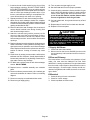
Shock and burn hazard.
C−Safety or Emergency Shutdown
G40UH(X) units are equipped with a hot surface ignition system. Do not attempt to light manually.
Disconnect main power to unit. Close manual and main gas
valves.
Gas Valve Operation (Figures 16, 15, 17 and 18)
1 − STOP! Read the safety information at the beginning of
this section.
2 − Set the thermostat to the lowest setting.
3 − Turn off all electrical power to the unit.
4 − This furnace is equipped with an ignition device which
automatically lights the burners. Do not try to light the
burners by hand.
5 − Remove the upper access panel.
6 − Honeywell VR8205 Gas Valve with On/Off Switch −
Move gas valve switch to OFF position. Do not
force. See figure 17.
Honeywell VR8205 Gas Valve with Control Knob −
D−Extended Period Shutdown
Turn off thermostat or set to UNOCCUPIED" mode. Close
all gas valves (both internal and external to unit) to guarantee no gas leak into combustion chamber. Turn off power to
unit. All access panels and covers must be in place and secured.
IV−HEATING SYSTEM SERVICE CHECKS
A−C.S.A. Certification
All units are C.S.A. (formally A.G.A. and C.G.A. combined)
design certified without modifications. Refer to the
G40UH(X) Installation Instruction.
B−Gas Piping
Gas supply piping should not allow more than 0.5"W.C. drop
in pressure between gas meter and unit. Supply gas pipe
must not be smaller than unit gas connection.
Page 24