1
Fifth Revision
BULTER SUN SOLUTIONS
9/07/2007
SERVICE MANUAL
connections should be used which can hold moisture and allow the electrical contract
between the wires to corrode, adding resistance to the sensor electrical circuit which will
be read by the controller as a decrease in the measured temperature. If the wire corrodes
completely through and breaks the circuit, the controller thinks the solar collector is
always below -50oF and will keep the pump off. If the tank sensor wire corrodes through,
then the controller thinks the hot water tank is below -50oF and will keep the pump on all
of the time, day and night.
Some of the newer controllers are using more accurate temperature sensors such as
platinum resistance thermometers, wire wound resistance elements, semiconductors and
thermocouples. These sensors are more expensive, but much more accurate, with
accuracy of plus or minus 1-2%.
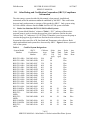
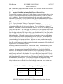
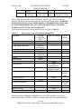
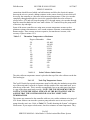
Table 2.5
Thermistor Temperature vs Resistance
Degrees Fahrenheit
-50
-25
0
25
50
75
100
125
150
175
200
225
250
2.6.1.1.1
Ohms
491,400
196,450
85,378
39,919
19,900
10,500
5,827
3,382
2,044
1,281
829
553
378
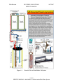
Solar Collector Outlet Sensor
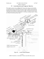
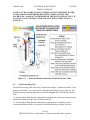
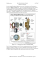
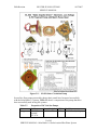
The solar collector temperature sensor is placed at the top of the solar collector on the hot
fluid outlet pipe.
2.6.1.1.2
Tank Top Temperature Sensor
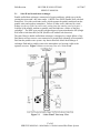
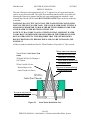
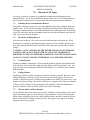
TheCut Off Switch for top tank temperature must be slid under the insulation to touch the
top of the metal tank. It must be in contact with the outside of the water tank itself, on or
near the top of the tank. This is usually accomplished close to an outlet port where there
is a gap in the sheet metal tank covering. NOTE: THE TOP SENSOR MUST BE IN
CONTACT WITH THE METAL SURFACE OF THE HOT WATER TANK TO
ASSURE THAT THE CONTROLLER WILL SAFELY LIMIT TANK
TEMPERATURE.
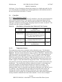
The sensors are connected to the controller with two wires with a minimum wire gauge of
#24. Sensor failures can cause the system to pump when the sun is not out, or not to
pump when the sun is out. Refer to Table 5.1 “Trouble shooting the System” to diagnose
a bad sensor. If you suspect a bad sensor, check its resistance at room temperature. They
34 of 65
SERVICE MANUAL: Solar Butler 1.0 Solar-Assisted Hot Water System