1
Air Top 3500/5000
9 Repair
9.2.2 Temperature Sensor, Replacement
•
•
NOTE
The temperature sensor may be replaced without
removal of the heater.
The internal temperature sensor may be substituted
against an external temperature sensor (see 9.1.2.1).
9.2.2.1 Removal
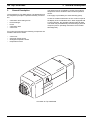
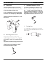
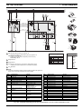
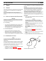
1. Remove cover (1, Fig. 901).
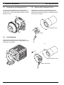
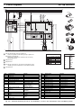
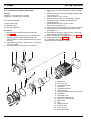
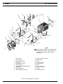
2. Pull temperature sensor (5, Fig. 902) from control unit
(1) and remove.
3. Perform procedures on components after
disassembly (refer to 9.1.1).
9.2.2.2 Installation
1. Plug temperature sensor (5, Fig. 902) into control unit.
2. Refit cover.
9.2.3 Temperature Limiter, Replacement
9.2.4 Control Unit, Replacement
9.2.4.1 Removal
1.
2.
3.
4.
5.
6.
Remove housing components/covers (see 9.2.1).
Remove insulation mat (15, Fig. 902).
Disconnect all connectors from control unit (1).
Remove torx screws (2).
Slide control unit (1) towards fan and remove.
Perform procedures on components after
disassembly (refer to 9.1.1).
9.2.4.2 Installation
1. Position control unit (1, Fig. 902) for installation on
combustion and heating air fan (7), slide towards fan
housing and secure with torx screws (2).
2. Tighten screws with 3.0 ± 0.3 Nm.
3. Connect all electrical connectors to control unit (1).
4. Fit insulation mat (15).
5. Assemble housing components/covers.
9.2.5 Combustion and Heating Air Fan (Drive),
Replacement
9.2.3.1 Removal
1. Remove housing components/covers (see 9.2.1).
2. Remove insulation mat (15, Fig. 902).
3. Disconnect connector of temperature limiter (3) from
control unit (1).
NOTE
The temperature limiter may be additionally fastened
with a washer. This washer must be replaced with a new
washer during installation.
4. Remove torx screw (4) and washer as required.
5. Remove temperature limiter (3).
6. Perform procedures on components after
disassembly (refer to 9.1.1).
9.2.3.2 Installation
CAUTION
The temperature sensor must be installed so that the
sensor element faces the heat exchanger.
NOTE
The drive (combustion and heating air fan) may only be
replaced as complete assembly. Repair is not possible.
CAUTION
The drive must only be replaced by a drive with the same
nameplate rating and the same ident.-no.
9.2.5.1 Removal
1.
2.
3.
4.
5.
6.
Remove housing components/covers (see 9.2.1).
Remove insulation mat (15, Fig. 902).
Remove gasket (16).
Remove control unit (see 9.2.4.1).
Remove torx screws (6).
Withdraw and remove combustion and heating air
fan (7).
7. Remove flat gasket (8) and discard.
8. Perform procedures on components after
disassembly (refer to 9.1.1).
9.2.5.2 Installation
1. Position temperature limiter (3, Fig. 902) for
installation and secure with torx screw (4) and washer
as required.
2. Tighten screw (4) with 2.5 ± 0.25 Nm.
3. Connect electrical connector of temperature limiter (3)
to control unit (1).
4. Fit insulation mat (15).
5. Assemble housing components/covers.
1. Place new flat gasket (8, Fig. 902) onto flange of heat
exchanger (14).
2. Position combustion and heating air fan (7) for
installation and secure with torx screws (6).
3. Tighten screws with 4.0 ± 0.4 Nm.
4. Install control unit (see 9.2.4.2).
5. Fit insulation mat (15).
6. Refit housing components / covers.
7. Fit seal (16).
HINWEIS
Adjust CO2 contents according to 6.2.1.
904