1
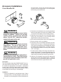
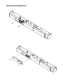
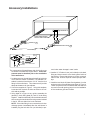
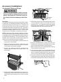
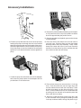
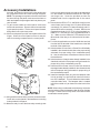
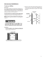
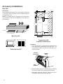
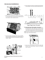
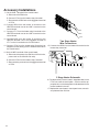
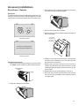
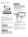
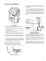
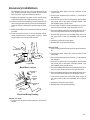
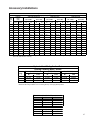
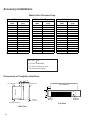
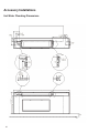
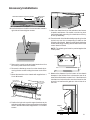
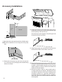
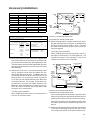
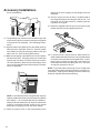
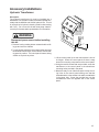
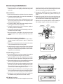
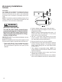
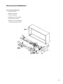
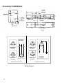
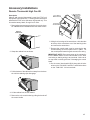
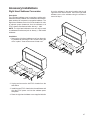
Accessory Installations Circut Breaker Kit WARNING Disconnect electrical power source before wiring the subbase. Failure to do so may result in injury or death from electrical shock. The unit OFF switch does not disconnect all power to the unit. CAUTION Use copper conductors only for electrical connections. The use of other types of conductors may result in galvanic corrosion, overheating and resultant equipment failure. WARNING All wiring must comply with applicable local and national codes. Type and location of fused disconnect switch(es) must comply with all applicable codes. Description The circuit breaker kit provides POWER ON/OFF and current overprotection function at the unit. The circuit breaker kit contains the appropriate circuit breaker, replacement access cover for the high voltage section of the subbase, mounting bracket and clips, and required hardware. Select circuit breaker kits according to unit amperage. Installation 1. Check circuit breaker for manufacturers name. Select mounting holes in mounting bracket to match part as indicated in the following figure (GE and Westinghouse 4 use outer holes). Secure one of the two small mounting clips to the mounting bracket. Do not fully tighten the mounting screw at this time. 2. Position the circuit breaker on the mounting bracket so that the locking tabs on the small clip (installed in Step 1) hold the circuit breaker on the mounting bracket. 3. Install the second small clip on the mounting bracket, locking the circuit breaker on the mounting bracket. Tighten both mounting screws securely. 4. Disconnect electrical power to the unit (if already wired). 5. Remove access cover from subbase. 6. Position the entire circuit breaker assembly in the subbase as shown in Figure 2. Using the two screws provided, secure the assembly to the subbase back wall in the subbase high voltage section. The large compression connections should be on the left (ON to the left, OFF to the right). 7. Connect the line voltage to the large compression terminals (left of breaker). Connect subbase wiring to the smaller compression connections (right of breaker). If a ground lug is provided, ground the lug to the unit. 8. Install the circuit breaker guard and the replacement access cover for the high voltage section. Install the assembly over the circuit breaker handle using the two screws removed from the original access cover.