1
I4
DOOR LOCK & THEFT DETERRENT
POWER DOOR LOCK SYSTEM------------- I41
OUTLINE-------------------------------- I41
DESCRIPTION------------------------- I41
SYSTEM WIRING DIAGRAM ----------- I41
LOCATION OF COMPONENTS--------- I43
CONTROL ------------------------------ I44
POWER DOOR LOCK CONTROL INTERLOCKING WITH DRIVER'S SEAT
DOOR LOCK-------------------------- I44
COMPONENTS ------------------------- I44
DOOR CONTROL RELAY -------------- I44
IMMOBILIZER SYSTEM -------------------- I45
OUTLINE-------------------------------- I45
DESCRIPTION------------------------- I45
NOTES ON IMMOBILIZER SYSTEM----- I45
SYSTEM DRAWING-------------------- I45
SYSTEM WIRING DIAGRAM ----------- I46
LOCATION OF COMPONENTS--------- I48
CONTROL ------------------------------ I49
BRIEF DESCRIPTION OF OPERATION
-------------------------------------- I49
IMMOBILIZER SYSTEM CONTROL ----- I49
TRANSPONDER COMMUNICATION
CONTROL -------------------------- I410
EFI ECU COMMUNICATION CONTROL
------------------------------------ I410
DIAGNOSIS ------------------------- I410
COMPONENTS ----------------------- I411
IG KEY ------------------------------ I411
IMMOBILIZER ECU ------------------ I411
IMMOBILIZER COIL ----------------- I411
EFI ECU----------------------------- I411
INDICATOR LAMP------------------- I411
I4-1
POWER DOOR LOCK SYSTEM
1 OUTLINE
1-1 DESCRIPTION
1. A power door lock has been provided for all vehicles. The front passenger seat door, the right and
left rear doors and the back door (luggage compartment door) can be locked and unlocked by
means of the driver's seat key cylinder operation.
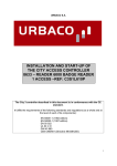
1-2 SYSTEM WIRING DIAGRAM
IG1
D/L
3
From
battery
6
8
7
4
B
E
ULSW
Driver seat door
lock control SW
M
4
2
1
1
LOK'
U/L'
Front door lock Ay RH
4
M
1
Rear door lock Ay RH
4
1
M
Rear door lock Ay LH
1
M
2
Door control relay
Back door lock Ay
P21B1546ES40
I4-2
Door lock connector terminal arrangement diagram
U/L'
U/L'
1
LOK'
LOK'
3
'B
2
4
ULSW
5
1
6
E
Door lock control relay
2
3
4
U/L'
5
1
LOK'
7
8
9 10
Front RH door lock motor
Rear LH door lock motor
Front RH door lock motor
2
Back door lock motor
6
1
5
2
6
3
7
E
8
4
9 10
ULSW
Driver's seat door
control switch
P21B5770ES16
I4-3
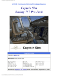
1-3 LOCATION OF COMPONENTS
a
b
b
c
d
c
P21B1548ES40
The illustration shows a typical example.
a
b
c
d
Door lock control relay
Front door lock Ay
Rear door lock Ay
Back door lock Ay
I4-4
2 CONTROL
2-1 POWER DOOR LOCK CONTROL INTERLOCKING WITH DRIVER'S SEAT
DOOR LOCK
1. When any of the following conditions are satisfied, all the other door locks will be set to "LOCK".
(1) When the driver's seat door lock lever is switched from the "UNLOCK" position to the "LOCK"
position
(2) When the key is inserted into the driver's seat key cylinder and turned in the "LOCK" direction
2. When any of the following conditions are satisfied, all the other door locks will be set to "UNLOCK".
(1) When the driver's seat door lock lever is switched from the "LOCK" position to the "UNLOCK"
position
(2) When the key is inserted into the driver's seat key cylinder and turned in the "UNLOCK" direction
3 COMPONENTS
3-1 DOOR CONTROL RELAY
1. The door control relay controls the "LOCK" and
"UNLOCK" functions of all doors, except the driver's seat
door.
J12B1554T10
I4-5
IMMOBILIZER SYSTEM
1 OUTLINE
1-1 DESCRIPTION
1. The immobilizer system is provided on some specifications.
2. The immobilizer system prohibits the unauthorized start of the engine, thus enhancing the security.
3. It becomes possible to start the engine when the ID code registered in the immobilizer ECU is
matched with the ID code memorized in the key.
4. When the immobilizer system is in the operating condition, the indicator lamp in the instrument
panel flashes.
1-2 NOTES ON IMMOBILIZER SYSTEM
1. In the case of the IG key for the immobilizer equipped vehicles, there are cases where correct
communication with the immobilizer ECU is impossible, thus not allowing the engine to start.
(1) When the grip section of the key is in contact with a metal object.
(2) When the key is close to or in contact with the key (Which incorporates a signal transmitter) for
the immobilizer system of another vehicle.
2. Do not put the IG key in ultrasonic cleaners, etc.
1-3 SYSTEM DRAWING
Communication
Transponder built-in key
Communication
Immobilizer computer
Engine control computer
L21B3001ES16
I4-6
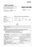
1-4 SYSTEM WIRING DIAGRAM
IG SW
ACC
F/L
AM1
IG1
IG2
AM2
ST
IG1
Fuse block
Battery
B/UP
ECU IG2
HORN HAZ
Engine control computer
Key
switch
DLC
9
SIO
10
T
3
KSW
1
'B
8
SIO2
2
IG
Immobilizer ECU
GND
7
COIL( COIL'
13
6
IND
14
Twist pair lead
Security indicator lamp
2
1
Immobilizer coil
P21B5500ES25
Immobilizer ECU connector terminal arrangement diagram
7
6
5
4
3
2
1
14 13 12 11 10 9
8
T11B8502S16
I4-7
Immobilizer ECU terminal name
Terminal No. Terminal code
1
B
2
IG
3
KSW
4
5
6
COIL+
7
GND
8
SIO2
9
SIO
10
T
11
12
13
COIL
14
IND
Terminal name
ECU power supply
IG SW power supply
Key SW
Transponder communication
Earth
Immobilizer communication
Diagnostic tester communication
Diagnostic tester communication
Transponder communication
Security indicator
I4-8
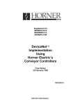
1-5 LOCATION OF COMPONENTS
d
b
a
c
P21B5503ES38
The illustration shows a typical example.
a
Immobilizer ECU
b
Steering column upper W/SW bracket
c
EFI ECU
d
Transponder
I4-9
2 CONTROL
2-1 BRIEF DESCRIPTION OF OPERATION
1. The key SW is turned "ON", when the key is inserted into the IG key cylinder.
2. The immobilizer ECU energizes the immobilizer coil. As a result, a magnetic field is generated in the
coil.
3. When the transponder (Chip) incorporated in the key receives the magnetic field of the coil, the ID
code memorized in the chip is transmitted.
4. The ID code is received by the immobilizer coil and sent to the immobilizer ECU.
5. The immobilizer ECU performs the collation of the transmitted ID code and the registered ID code.
When the codes are matched, the communication with the EFI ECU is permitted. ("UNSET" condition.) (In cases where the collation of the codes is not performed correctly, the communication with
the EFI ECU remains prohibited. ("SET" condition.) (Therefore, even if the IG SW is turned "ON", the
communication with the EFI ECU will not be started.)
6. When the IG SW is turned "ON" by turning the IG knob, the collation of the code with the EFI ECU is
carried out.
7. If the collation of the codes is correct, the engine is started by turning the IG knob to the "START"
position.
Key insertion switch "ON"
Immobilizer ECU (Transponder communication control)
Energizing of the immobilizer coil and generation of magnetic fields
Receiving of key magnetic field
Sending of key ID code
Immobilizer coil (Receiving the ID code)
Immobilizer coil (Sending the ID code)
Immobilizer ECU (Collation of the ID codes)
Operation of the ignition knob (The engine starts.)
EFI computer (communication with immobilizer ECU)
T11E1511ES20
2-2 IMMOBILIZER SYSTEM CONTROL
2-2-1 IMMOBILIZER SYSTEM OPERATING CONDITION
1. When the following conditions are satisfied, the immobilizer system is set to the operating condition.
(Communication with the EFI ECU prohibited.)
(1) The key SW is "OFF" as well as the IG SW is at "LOCK" or "ACC" position
(2) Thirty seconds have passed after the key SW is "ON", and the IG SW is changed from "ON"
"LOCK" or "ACC" position
2-2-2 IMMOBILIZER SYSTEM RELEASED CONDITION
1. When the following conditions are satisfied, the immobilizer system is set to the released condition.
(Communication with the EFI ECU allowed.)
(1) When the ID code stored in the key and the ID code stored in the immobilizer ECU match
I4-10
2-3 TRANSPONDER COMMUNICATION CONTROL
2-3-1 TRANSPONDER COMMUNICATION STARTING CONDITION
1. If any of the following conditions is met, the transponder communication (Check of the ID code of
the key) starts.
(1) In the immobilizer system "SET" condition, the key SW is "OFF" "ON"
(2) In the immobilizer system "SET" condition, the IG SW is changed from "LOCK" or "ACC" position
"ON"
(3) In the immobilizer system "SET" condition, the key SW is "ON" and the IG SW is changed from
"ON" "LOCK" or "ACC" position
(4) In the immobilizer system "SET" condition, the key SW is turned "ON" or the IG SW is turned
"ON" after the ECU power "ON" reset is released
2-3-2 TRANSPONDER COMMUNICATION FINISHING CONDITION
1. When any of the following conditions is satisfied, the transponder communication (Key ID code verification) is finished.
(1) The key SW is "OFF" as well as the IG SW is at "LOCK" or "ACC" position
(2) Three seconds has passed after the key SW is turned from "OFF" "ON"
(3) Three seconds has passed after the IG SW is turned from "OFF" "ON"
(4) Three seconds has passed after the key SW is turned "ON" and the IG SW is turned from "OFF"
"ON"
(5) The ID code registered in the immobilizer ECU matches the ID code memorized in the key
(6) After an ID code not registered in the immobilizer ECU has been received three times and the
key ID has been read properly
2-4 EFI ECU COMMUNICATION CONTROL
2-4-1 EFI ECU COMMUNICATION STARTING CONDITION
1. When the immobilizer system has been released and the IG SW is set to "LOCK", or set from "ACC"
"ON", the immobilizer ECU communicates with the EFI ECU.
2-4-2 EFI ECU COMMUNICATION FINISHING CONDITION
1. If any of the following conditions is met, the immobilizer ECU will inhibit communication with the EFI
ECU.
(1) During communicating with the EFI ECU, the IG SW is changed from "ON" "LOCK" or "ACC"
position
(2) Immobilizer system "SET" status
(3) Communication with the EFI ECU is complete
2-5 DIAGNOSIS
2-5-1 DESCRIPTION
1. The diagnosis means "Trouble diagnosis". In cases where an abnormality exists in the input/output
system, the computer inside the sensor unit informs the check operator of the abnormal items.
2. For the details of the diagnosis, refer to the repair manual.
I4-11
3 COMPONENTS
3-1 IG KEY
1. A transponder (Chip) is incorporated in the grip section
of the IG key. Upon receiving the magnetic field generated by the immobilizer coil, this chip sends the ID code.
Moreover, the ID code differs, depending on the IG key.
Transponder
T11B1507ET16
3-2 IMMOBILIZER ECU
1. The immobilizer coil is energized and the transponder communication is performed. Furthermore,
the collation of ID codes is carried out with the EFI ECU.
2. It is possible to register up to four keys. Even when the battery is disconnected, the memory of ID
codes of the registered key will not be lost.
3-3 IMMOBILIZER COIL
1. When electric current flows into the immobilizer coil due
to the immobilizer ECU control, a magnetic field is generated and the ID code is received from the key.
Immobilizer coil
L31B2529ET16
3-4 EFI ECU
1. The ID code is collated by the signal from the immobilizer ECU, thus controlling the injection of fuel.
3-5 INDICATOR LAMP
1. When the immobilizer system is in the operating condition, the indicator lamp in the instrument
panel flashes.