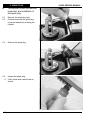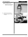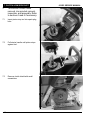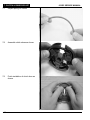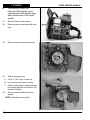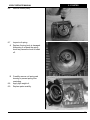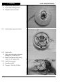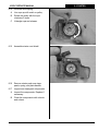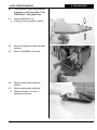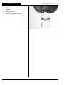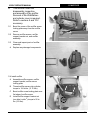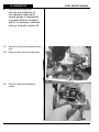
1
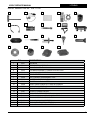
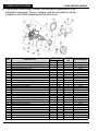
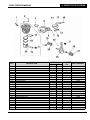
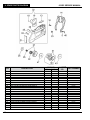
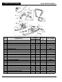
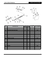
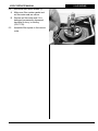
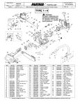
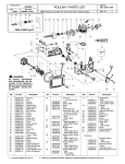
633GC
SERVICE MANUAL
F/N 73472 Oct 07
© 2007 ICS, Blount Inc.
633GC SERVICE MANUAL
TITLE
TABLE OF
CONTENTS
SECTION
SECTION TITLE
PAGE NUMBER
SHOP MANUAL USE
2
1
TOOLS
3
2
SAW SPECIFICATIONS
4
3
SERIAL NUMBER LOCATION
5
4
SPARE PARTS DIAGRAM (TORQUE AND LOCTITE®)
6
5
AIR INTAKE
14
6
SPARK PLUG
16
7
CLUTCH & RIM SPROCKET
18
8
STARTER SYSTEM
22
9
WALLWALKER
27
10
CYLINDER COVER
29
11
MUFFLER
31
12
CARBURETOR
32
13
CYLINDER & PISTON
34
14
WATER HOSE & CAP
41
15
IGNITION COIL
43
16
FLYWHEEL
45
17
BOTTOM GUARD
47
18
FRONT HANDLE
48
19
FUEL TANK
49
20
CRANKCASE
52
21
BAR STUD
60
22
TENSIONER
61
23
CARBURETOR TUNING
62
24
IDLE SPEED ADJUSTMENT
66
25
TROUBLESHOOTING DIAGRAMS
67
26
TROUBLESHOOTING: FUEL SYSTEM LEAKS
69
27
TROUBLESHOOTING: CRANKCASE LEAKS
72
APPENDIX
1. SPARK PLUG REFERENCE GUIDE
F/N 73472 Oct 07
© 2007 ICS, Blount Inc.
73
1
SHOP MANUAL
TITLE USE
633GC SERVICE MANUAL
Shop Manual Use
This manual contains all the technical information necessary for carrying out repairs on the
633GC cut-off saw. For safe, efficient work, it is of prime importance that the values indicated
be adhered to. Routine periodic maintenance is covered in the operator’s manual included with
each cut-off saw.
General Shop Rules
• Always use the right tools for the job, otherwise components may be damaged.
• Use a plastic dead blow mallet to separate parts attached solidly to each other.
• Mark mating parts as a reassembly reference.
• Keep component parts together as a group. Assemble screws and nuts into appropriate
subgroups.
• When reassembling, clean all parts carefully, lubricate moving parts and replace all oil seals,
o-rings, gaskets, washers and self-locking nuts.
• For best results, use only original ICS® replacement parts.
General Recommendations
• Some procedures in this manual require the use of special tools. A complete tool kit for the
633GC is available from ICS®.
• Detailed carburetor maintenance and overhaul information is available in Walbro’s Diaphragm Carburetor Service Manual. Walbro can be contacted at http:\\www.walbro.com
or by calling 1.989.872.2131.
2
© 2007 ICS, Blount Inc.
F/N 73472 Oct 07
633GC SERVICE MANUAL
1. TITLE
TOOLS
633GC Service Tool Kit - P/N 71700
1
2
3
4
5
6
7
8
9
10
11
12
13
14
15
16
17
18
19
P/N
DESCRIPTION
1
71521
SCRENCH
2
71541
PRESSURE GAUGE BULB
3
71542
COIL/FLYWHEEL TIMING SHIM
4
71543
CYLINDER ASSEMBLY CLAMPS & PISTON STOP
5
71546
613 SHOCK ABSORBER TOOL
6
71547
SPARK TESTER
7
71548
613 FLYWHEEL DISASSEMBLY TOOL
8
71550
LIMITER CAP REMOVAL TOOL
9
71565
ELECTRONIC TACHOMETER
10
71569
613GC INDUCTION SEAL FLANGE W/ SCREWS
11
71570
613GC EXHAUST SEAL FLANGE W/SCREWS
12
71573
TUNING SCREWDRIVER
13
73410
633GC FLYWHEEL PULLER
14
73425
633GC FUEL PRESSURE CAP
15
73428
613GC & 633GC MAIN BEARING DRIVER TOOL
16
73429
633 MAIN BEARING SPACING TOOL
17
73430
633GC SHOCK ABSORBER TOOL
18
73431
633GC INTAKE PORT COVER TOOL
19
73432
633GC EXHAUST PORT COVER TOOL
F/N 73472 Oct 07
© 2007 ICS, Blount Inc.
3
2. SPECIFICATIONS
TITLE
633GC SERVICE MANUAL
Specifications
Engine Type
2-Stroke Single Cylinder Air Cooled
Displacement
6.2 cu.inch (101 cc)
Horsepower
6.1 hp (4.6 kw) @ 8700 rpm
Engine Speed
11,500 ± 500 rpm, mechanically governed
2500-2800 rpm @ idle
Piston ring gap (Maximum)
.040 in. (1 mm)
Chain Speed
4950 fpm (25 m/s), free running
4000 fps (20 m/s), in the cut
Weight
27.5 lbs. (12.5 kg)
Cutting Depth
Up to 16 inches (40.6 cm)
Dimensions
23 inches (58 cm) length
14 inches (35 cm) height
12 inches (30 cm) width
Carburetor
Walbro diaphragm WGAK3 w/ throttle shaft seals
Air Filtration
Washable cotton (K&N) or washable dry nylon
Starter
Dust and water shielded
Ignition
Electronic, water sealed
Spark plug type
Champion RCJ-7Y (for conversion chart see appendix)
Clutch
Three-weight, single spring, centrifugal
Fuel Mix Ratio
25:1 gasoline to oil with oil brand name gasoline and ICS® 2-stroke
engine oil, or other high quality 2-stroke engine oil for air cooled
engines.
Fuel Capacity
.26 gal (1 liter)
15-18 minute run time
Water Supply
Minimum 20 psi (1.5 bar)
Noise Level
102 dB @ 1 meter
Vibration Level
8 m/s @ front handle
Cutting Rate
Hard aggregates w/ steel: 15-25 sq-in/min (90-160 sq-cm/min)
Medium aggregates: 20-30 sq-in/min (160-190 sq-cm/min)
Masonry, soft aggregates: 30-50 sq-in/min (190-320 sq-cm/min)
4
© 2007 ICS, Blount Inc.
F/N 73472 Oct 07
633GC SERVICE MANUAL
TITLE
3. SERIAL
# LOCATION
3 This section shows the two locations of the serial number.
F/N 73472 Oct 07
© 2007 ICS, Blount Inc.
5
4. SPARE PARTS
TITLE DIAGRAM
633GC SERVICE MANUAL
4 This section covers torque, Loctite®, and lubrication requirements of the
individual components. The key numbers used are not related to the key
numbers in the 633GC Replacement Parts Price List.
6
TORQUE
Nm
in‑lbs.
KEY
DESCRIPTION
1
2
3
4
5
6
7
8
9
10
11
12
13
14
15
16
17
18
19
20
22
23
24
25
26
27
28
31
32
STARTER ROPE
STARTER ROPE RETAINER
STARTER ROPE HANDLE
STARTER HOUSING OIL CAP
SCREW
STARTER COVER
STARTER ROPE WASHER
STARTER COIL SPRING & HOUSING
STARTER SPRING COVER
STARTER BUSHING
STARTER ROPE PULLEY
STARTER PULLEY WASHER
STARTER PULLEY SCREW
STARTER PULLEY COVER
STARTER PULLEY COVER SCREW
STARTER COVER DUST SHIELD
STARTER COVER ASSEMBLY (COMPLETE)
IGNITION TOGGLE SWITCH
IGNITION TOGGLE PLATE ON/OFF
IGNITION TOGGLE SWITCH NUT
SPARK PLUG CAP
SPARK PLUG CAP SPRING
IGNITION COIL WITH SPARK PLUG LEAD & PRIMARY
IGNITION COIL MOUNTING SCREW
WASHER
FLYWHEEL MOUNTING WASHER
FLYWHEEL MOUNTING NUT
STARTER PAWL KIT
FLYWHEEL ASSEMBLY REPLACEMENT KIT
© 2007 ICS, Blount Inc.
LOCTITE®
PART NUMBER
272
5
43
X
3
26
X
2
17
X
4
35
6
52
X
73188
73228
73189
73229
73230
73190
73231
73191
73232
73192
73193
73233
73234
73235
73236
73194
73195
73237
73238
73239
73241
73242
73196
73243
73897
73245
73246
504386
73433
F/N 73472 Oct 07
633GC SERVICE MANUAL
KEY
1
2
3
4
5
6
7
10
11
12
13
14
15
16
17
18
19
20
22
23
24
25
26
27
TITLE DIAGRAM
4. SPARE PARTS
TORQUE
Nm
in‑lbs.
DESCRIPTION
SPARK PLUG
WASHER
CYLINDER BLOCK BOLT
CYLINDER TO MUFFLER GASKET
EXHAUST PIPE
WRIST PIN NEEDLE BEARING
EXHAUST PIPE MOUNTING SCREW
CRANKSHAFT SEAL FLYWHEEL SIDE
MUFFLER BODY
MUFFLER SUPPORT BRACKET SCREW
MUFFLER SUPPORT BRACKET NUT
MUFFLER SUPPORT BRACKET
MUFFLER SCREW LOCKING PLATE
MUFFLER MOUNTING SCREW
CYLINDER BASE GASKET
PISTON RING PAIR
WRIST PIN SNAP RING
PISTON WRIST PIN
COMPLETE CYLINDER/PISTON ASSEMBLY
CRANKSHAFT FLYWHEEL WOODRUFF KEY
CRANKSHAFT BEARING (FLYWHEEL END)
CRANKSHAFT ASSEMBLY
CRANKSHAFT BEARING (CLUTCH SIDE)
CRANKCASE OUTSIDE SEAL-CLUTCH SIDE
F/N 73472 Oct 07
27
243
12
104
4
35
4
2.25
43
26
© 2007 ICS, Blount Inc.
LOCTITE®
PART NUMBER
272
X
X
X
73199
73250
73251
73434
73253
73211
73254
73201
73203
73255
73256
73204
73257
73258
73436
73437
73259
73208
73442
73264
73209
73443
73200
73202
7
4. SPARE PARTS
TITLE DIAGRAM
8
633GC SERVICE MANUAL
© 2007 ICS, Blount Inc.
F/N 73472 Oct 07
633GC SERVICE MANUAL
KEY
TITLE DIAGRAM
4. SPARE PARTS
TORQUE
Nm
in‑lbs.
DESCRIPTION
1
CRANKCASE LEFT HALF
2
CRANKCASE RIGHT HALF
3
BOLT
4
WASHER
5
TRIGGER ROD GROMMET
6
TRIGGER ROD BUSHING
7
BUMPER, SHOCK ABSORBER, FUEL TANK TOP
8
CHOKE LEVER GROMMET
9
CHOKE LEVER
10
FUEL LINE GROMMET (CRANKCASE)
11
MAIN BEARING SEAL HOUSING ASSMBLY-CLUTCH SIDE
12
SCREW
13
BAR MOUNTING STUD
14
CRANKCASE GASKET
15
CRANKCASE DOWEL PIN
18
PREMIUM TENSIONER KIT (REPLACES 73283), ASSEMBLY
19
BAR MOUNT PAD COVER PLATE
20
SCREW
21
WASHER
22
CRANKCASE OUTSIDE SEAL-CLUTCH SIDE
23
CRANKCASE PLUG O-RING
24
CRANKCASE PLUG
25
SEAL HOUSING O-RING
26
SEAL HOUSING MOUNTING SCREW (3)
27
CLUTCH SIDE MAIN BEARING SEAL-INSIDE
31
WATER TUBE (IN TANK)
32
WATER TUBE FITTING
33
TUBE FITTING-BACKSIDE BAR MOUNT
38
COVER GUARD MOUNTING WASHER
39
COVER GUARD MOUNTING BOLT
40
COVER GUARD
52
WATER TUBE O-RING
53
633GC PLASTIC CAP
Not Shown. Gasket Set, includes parts 73434, 73436, 73456
F/N 73472 Oct 07
© 2007 ICS, Blount Inc.
8
19.5
69
173
LOCTITE®
PART NUMBER
272
X
X
X
3
26
X
3
26
X
73444
73445
73278
73897
73268
73269
73270
73389
73213
73390
73446
73275
73280
73447
73281
73935
73225
73284
73285
73202
73391
73286
73287
73288
73289
73384
73385
73386
73396
73397
70967
71468
504389
73435
9
4. SPARE PARTS
TITLE DIAGRAM
KEY
5
10
13
14
18
19
20
21
22
23
25
26
27
30
31
32
43
44
45
46
47
10
DESCRIPTION
633GC SERVICE MANUAL
TORQUE
Nm
in‑lbs.
WASHER
SHOULDER SCREW, HAND GUARD
633GC SIDE COVER PLUG KIT
633GC HAND GUARD
SCREW
COVER SIDE BAR PLATE
RUBBER BUMPER, COVER
COVER RUBBER FLAP
SIDE COVER W/O BRAKE COMPONENTS
COVER CLAMPING NUT
CLUTCH SPACER WASHER
CLUTCH NEEDLE BEARING
CLUTCH CUP WITH SPLINED ADAPTER
CLUTCH SPRING
CLUTCH ASSEMBLY
8T RIM SPROCKET KIT
CLUTCH SHIELD
CHAIN COVER RUBBER INSERT-MIDDLE
CHAIN COVER RUBBER INSERT-TOP
633GC HAND GUARD SCREW
633GC CLUTCH SPACER
LOCTITE®
PART NUMBER
272
X
5
© 2007 ICS, Blount Inc.
44
73897
71436
71441
71435
73284
73309
73310
73311
73449
73313
73314
73423
70948
73317
73451
70949
73452
73315
73316
71437
504568
F/N 73472 Oct 07
633GC SERVICE MANUAL
KEY
1
2
3
4
5
6
7
8
9
10
11
12
13
14
15
16
17
18
19
20
21
22
23
24
25
26
27
TITLE DIAGRAM
4. SPARE PARTS
TORQUE
Nm
in‑lbs.
DESCRIPTION
FILTER COVER KNOB
WASHER
FILTER KNOB O-RING
AIR FILTER COVER ASSEMBLY
SCREW
CYLINDER COVER
CARBURETOR ATTACHMENT SCREW
CARBURETOR ATTACHMENT SCREW WASHER
INTAKE MANIFOLD RUBBER
INTAKE MANIFOLD BRACKET
FILTER CANNISTER COVER
O-RING, AIR FILTER
AIR FILTER GASKET
AIR FILTER CANNISTER, POLY
FILTER CANNISTER GASKET
PREFILTER PLASTIC, SECONDARY FILTER
FILTER SUPPORT SCREW
FILTER SUPPORT
CARBURETOR STANDOFF SUPPORT
BOLT
CARBURETOR SUPPORT SCREW
CARBURETOR MIXTURE SCREW GROMMET
CARBURETOR
INSULATOR TO CYLINDER GASKET
CARBURETOR INSULATOR
INSULATOR FOAM GASKET
CARBURETOR TO INSULATOR GASKET
F/N 73472 Oct 07
LOCTITE®
PART NUMBER
272
3
26
5
43
X
5
43
X
5
43
X
6
3
52
26
X
X
© 2007 ICS, Blount Inc.
73320
73897
73322
71721
73230
71722
73326
73327
73328
73329
73330
73331
71719
71752
73335
73336
73337
73338
73387
73278
73340
73341
73454
73455
73344
73345
73456
11
4. SPARE PARTS
TITLE DIAGRAM
KEY
1
2
3
4
5
6
7
8
9
10
11
12
13
14
15
16
17
18
19
20
21
22
23
24
25
26
27
12
633GC SERVICE MANUAL
TORQUE
Nm
in‑lbs.
DESCRIPTION
FRONT HANDLE ASSEMBLY
WASHER
FRONT HANDLE BOLT
TRIGGER LOCK PIN
TRIGGER LOCK PIN WASHER
TRIGGER LOCK SPRING
TRIGGER LOCK BUTTON
TRIGGER PIVOT PIN
THROTTLE LEVER
TRIGGER LOCKOUT LEVER
TRIGGER LOCKOUT LEVER SPRING
FUEL TANK ASSEMBLY
SCREW
THROTTLE OPERATING WIRE
MOUNTING NUT
REAR HANDLE REAR BOLT
REAR HANDLE ASSEMBLY
FUEL CAP ASSEMBLY
FUEL CAP O-RING
FUEL TANK SCREW
FUEL FILTER
FUEL LINE
FUEL BREATHER PIPE
SHOCK ABSORBER
WASHER
SCREW (REAR HANDLE, UPPER)
BUMPER, SHOCK ABSORBER, FUEL TANK TOP
© 2007 ICS, Blount Inc.
LOCTITE®
PART NUMBER
272
5
43
X
7
61
X
3
26
X
5
43
X
3
26
X
73457
73897
73349
73353
73354
73355
73356
73357
73358
73359
73360
73458
73275
73366
73367
73368
73369
73370
73448
73372
73459
73375
73376
73377
73250
73379
73270
F/N 73472 Oct 07
633GC SERVICE MANUAL
KEY
34
35
36
37
41
42
43
44
45
46
47
49
50
51
54
55
56
57
58
59
60
61
62
63
64
DESCRIPTION
COVER GUARD FRONT MOUNT NUT
HOSE HANGER BUTTON
FITTING
WALLWALKER SIDE ARM SCREW
FITTING
COPPER WASHER
633GC WATER CAP
FUEL CAP O-RING
WATER HOSE
HOSE HANGER
HOSE CLAMP
WATER HOSE SCREW
GUARD FLAP CLAMP
GUARD FLAP
GUARD FLAP WASHER
WATER HOSE COVER
WATER SHUT-OFF VALVE
WATER HOSE O-RING
RING NUT
FITTING
WATER HOSE GASKET
WASHER
GUARD FLAP SPACER
633GC WALLWALKER LEVER ARM
GUARD FLAP SCREW
F/N 73472 Oct 07
TITLE DIAGRAM
4. SPARE PARTS
TORQUE
Nm
in‑lbs.
0.5
43
0.5
43
© 2007 ICS, Blount Inc.
LOCTITE®
PART NUMBER
272
X
73392
71744
71454
71478
71453
71456
504388
73448
71455
71461
71465
71463
71531
71534
71483
71464
71458
71468
71457
71467
71469
73951
71480
504387
71479
13
5. AIR
INTAKE
TITLE
5
This section covers the
disassembly, inspection, and
assembly of the air intake.
5.1
Loosen the air filter cover screw and
remove air filter cover.
5.2
Remove filter canister cover and air
filter.
633GC SERVICE MANUAL
A Inspect air filter.
B Replace filter if necessary (P/N
71752)
5.3
Remove pre filter from air filter
mount.
A Clean filter with cleaning solution and
water.
B Let dry and reinstall.
14
© 2007 ICS, Blount Inc.
F/N 73472 Oct 07
633GC SERVICE MANUAL
5.4
TITLE
5. AIR
INTAKE
Secure air filter mount screws (3).
A Make sure filter canister gasket and
air filter water seal are secure.
B Replace air filter water seal if it is
damaged, permanently depressed,
hard due to slurry, or missing
(P/N 71719).
5.5
Assemble filter system in the reverse
order.
F/N 73472 Oct 07
© 2007 ICS, Blount Inc.
15
6. SPARK
TITLEPLUG
6
This section covers the removal,
inspection, and installation of
the spark plug.
6.1
Remove the spark plug lead.
6.2
Clean area around the spark plug
to prevent debris from entering the
cylinder.
6.3
Remove the spark plug.
6.4
Inspect the spark plug.
633GC SERVICE MANUAL
A If dirty clean with a wire brush as
shown.
16
© 2007 ICS, Blount Inc.
F/N 73472 Oct 07
633GC SERVICE MANUAL
TITLEPLUG
6. SPARK
B Gap if necessary to 0.20” (0.5 mm).
NOTE:If the sparkplug must be
replaced refer to the Spark Plug
Reference Guide on page 70.
6.5
Assemble in the reverse order.
A Make sure the plug boot is seated
completely.
F/N 73472 Oct 07
© 2007 ICS, Blount Inc.
17
7. CLUTCH &TITLE
RIM SPROCKET
7
This section covers clutch
removal, rim sprocket removal,
inspection, and assembly. Refer
to sections 5 and 6 if necessary.
7.1
Insert piston stop tool into spark plug
hole.
7.2
Pull starter handle until piston stops
against tool.
7.3
Remove clutch shield with small
screwdriver.
18
633GC SERVICE MANUAL
© 2007 ICS, Blount Inc.
F/N 73472 Oct 07
633GC SERVICE MANUAL
7.4
TITLE
7. CLUTCH &
RIM SPROCKET
Remove clutch.
Left hand threads - rotate
clockwise to loosen.
NOTE:If an impact wrench is available
steps 7.1 and 7.2 do not have to
be performed.
7.5
Remove all drive components.
7.6
Inspect the clutch shoes for wear.
A Replace if the shoe has less than
0.04” (1 mm) of material, as shown.
F/N 73472 Oct 07
© 2007 ICS, Blount Inc.
19
7. CLUTCH &
RIM SPROCKET
TITLE
7.7
Inspect spring for cracks.
7.8
Assemble clutch shoes as shown.
7.9
Finish installation of clutch shoe as
shown.
20
633GC SERVICE MANUAL
© 2007 ICS, Blount Inc.
F/N 73472 Oct 07
633GC SERVICE MANUAL
7.10
TITLE
7. CLUTCH &
RIM SPROCKET
Inspect the rim sprocket for wear.
A Replace if the rim sprocket teeth are
worn to points, as shown on right.
7.11
Clean and assemble.
A Clean all parts in solvent.
B Grease clutch cup bearing with a
waterproof grease (ICS® P/N 70885).
C Assemble clutch: use spacer washer,
bearing, clutch cup with rim sprocket,
inside clutch spacer washer, and
clutch assembly.
7.12
Install clutch.
A Tighten firmly.
Left hand threads.
F/N 73472 Oct 07
© 2007 ICS, Blount Inc.
21
8. STARTER
TITLE
8
This section covers the
removal of the starter cover,
replacement of the starter rope,
and replacement of the recoil
spring.
8.1
Remove starter cover screws.
8.2
Remove starter cover assembly from
saw.
8.3
Remove starter cord shield screws.
8.4
Relieve spring tension.
633GC SERVICE MANUAL
A Pull 4-6” (10-15 cm) of rope out.
B Line rope up with notch on pulley.
C Slowly rotate pulley counterclockwise
until spring pressure is released. Use
thumb as a brake.
8.5
Remove starter pulley screw and
washer.
NOTE:Hold starter cover firmly.
22
© 2007 ICS, Blount Inc.
F/N 73472 Oct 07
633GC SERVICE MANUAL
8.6
Remove starter pulley.
8.7
Inspect coil spring.
TITLE
8. STARTER
A Replace if spring hook is damaged.
Attempting to re-bend the spring
hook may cause the hook to break
off.
B Carefully remove coil spring and
housing to prevent spring from
unwinding.
8.8
Apply light weight oil.
8.9
Replace parts carefully.
F/N 73472 Oct 07
© 2007 ICS, Blount Inc.
23
8. STARTER
TITLE
633GC SERVICE MANUAL
8.10 Inspect pulley spring catch.
A Clean with cleaning solution.
B Replace if worn or broken.
8.11 Install starter rope and tie knot.
8.12 Install pulley
A Wind rope onto pulley clockwise
leaving 4-6” (10-15 cm) out.
B Make sure that the pulley spring
catch is in the spring hook.
8.13 Install center screw.
A Use blue Loctite®.
B Torque to 26 in-lbs. (2.9 Nm).
24
© 2007 ICS, Blount Inc.
F/N 73472 Oct 07
633GC SERVICE MANUAL
TITLE
8. STARTER
8.14 Wind the recoil spring.
A Line rope up with notch on pulley.
B Rotate the pulley with the rope
clockwise 5 times.
C Untangle rope and release.
8.15 Assemble starter cord shield.
8.16 Remove starter pawl snap rings,
pawls, spring, and plain washer.
8.17 Inspect and clean pawl components.
A Inspect the components. Replace if
necessary.
B Clean the components with a brush
and solvent.
F/N 73472 Oct 07
© 2007 ICS, Blount Inc.
25
8. STARTER
TITLE
633GC SERVICE MANUAL
8.18 Assemble components
A Make sure the snap ring spring is in
the correct position.
B Make sure the spring is in the correct
position.
8.19 Install starter cover.
A Pull out cord 4-6” (10-15 cm). Slowly
release while placing cover to allow
pawls to engage.
8.20 Install starter cover screws.
A Use blue Loctite”.
B Torque to 60 in-lbs. (6.8 Nm). 26
© 2007 ICS, Blount Inc.
F/N 73472 Oct 07
633GC SERVICE MANUAL
9
This section covers the removal,
inspection, and assembly of the
WallWalker ® and guard flap.
9.1
Inspect WallWalker ® tip.
TITLE
9. WALLWALKER
A If the tip is worn as shown, replace.
9.2
Remove crankcase screws and wave
washers.
9.3
Remove WallWalker ® from saw.
9.4
Remove guard flap screws and
washer.
9.5
Remove and inspect guard flap.
A Replace the flap if it is torn or
damaged in any way.
F/N 73472 Oct 07
© 2007 ICS, Blount Inc.
27
9. WALLWALKER
TITLE
9.6
633GC SERVICE MANUAL
Assemble in the reverse order.
A Install crankcase screws and wave
washers.
B Use blue Loctite®.
C Torque to 70 in-lbs. (7.9 Nm).
28
© 2007 ICS, Blount Inc.
F/N 73472 Oct 07
633GC SERVICE MANUAL
10
TITLE COVER
10. CYLINDER
This section covers the
disassembly and assembly of
the cylinder cover. Removal of
the air intake components and
front handle is required. Refer to
sections 5 and 18 if necessary.
10.1 Remove the cylinder cover screws.
10.2 Remove spark plug lead from
cylinder cover.
10.3 Partially remove intake manifold from
cylinder cover while lifting cylinder
cover away from saw.
10.4 Inspect cylinder cover for damage.
A Replace if necessary.
10.5 Make sure carburetor screw boot and
cylinder cover plug are in place.
F/N 73472 Oct 07
© 2007 ICS, Blount Inc.
29
10. CYLINDER
TITLE COVER
633GC SERVICE MANUAL
10.6 Install cylinder cover.
A Pull spark plug lead into slot in
cylinder cover.
B Push the cylinder cover down on the
crankcase, guide intake manifold into
cylinder cover.
10.7 Push down cylinder cover until it sits
flat on crankcase.
A Install the cylinder cover screws
using blue Loctite®.
B Torque to 35 in-lbs. (4.0 Nm).
30
© 2007 ICS, Blount Inc.
F/N 73472 Oct 07
633GC SERVICE MANUAL
11
This section covers the
disassembly, inspection,
and assembly of the muffler.
Removal of the WallWalker ®
and cylinder cover is required.
Refer to sections 9 and 10 if
necessary.
11.1
Bend the corner of the muffler screw
locking plate away from the muffler
screw.
TITLE
11. MUFFLER
11.2 Remove muffler screws, muffler
support bracket nut, and muffler
assembly.
11.3 Clean and inspect parts of muffler
assembly.
A Replace any damaged components.
11.4 Install muffler.
A Assemble muffler screws, muffler
support bracket, muffler screw
locking plate.
B Thread muffler screws into cylinder;
torque to 104 in-lbs. (11.75 Nm).
C Bend muffler screw locking plate over
flat edge of muffler screw.
D Install muffler support bracket nut
(use blue Loctite®); torque to 26 inlbs. (2.9 Nm).
F/N 73472 Oct 07
© 2007 ICS, Blount Inc.
31
12. CARBURETOR
TITLE
12
633GC SERVICE MANUAL
This section covers the
removal, and installation of
the carburetor. Removal of
several groups of components
is needed. Refer to sections 5
and 10. If necessary, carburetor
tuning is covered in section 23.
12.1 Remove fuel line from carburetor and
plug.
12.2 Remove choke lever from carburetor.
12.3 Remove carburetor attachment
screws.
32
© 2007 ICS, Blount Inc.
F/N 73472 Oct 07
633GC SERVICE MANUAL
TITLE
12. CARBURETOR
12.4 Remove intake manifold.
12.5 Remove carburetor.
A Lift and twist carburetor away from
throttle linkage to remove.
12.6 Assemble in the reverse order.
A Torque carburetor body screws to
43 in-lbs. (4.9 Nm).
F/N 73472 Oct 07
© 2007 ICS, Blount Inc.
33
13. CYLINDER
TITLE& PISTON
13
633GC SERVICE MANUAL
This section covers the
disassembly, inspection and
assembly of the cylinder, piston
and related components.
Removal of several component
groups is required. Refer to
sections 5, 6, 10, and 12 if
necessary.
13.1 Remove insulator base screws.
A Remove carburetor insulator from
cylinder.
13.2 Remove cylinder screws (4) and
wave washers.
34
© 2007 ICS, Blount Inc.
F/N 73472 Oct 07
633GC SERVICE MANUAL
TITLE& PISTON
13. CYLINDER
13.3 Remove cylinder.
A Remove cylinder gasket and clean
case.
13.4 Remove wrist pin retaining clips
13.5 Press wrist pin out with an 8 mm
deep socket.
13.6 Remove piston and inspect. Replace
if damaged.
F/N 73472 Oct 07
© 2007 ICS, Blount Inc.
35
13. CYLINDER
TITLE& PISTON
633GC SERVICE MANUAL
13.7 Remove wrist pin bearing.
13.8 Cylinder gasket
A Oil gasket with ICS® 2-stroke
engine oil.
B Install gasket and align holes and
notch.
13.9 Install wrist pin bearing in rod.
A Oil bearing with ICS® 2-stroke
engine oil.
36
© 2007 ICS, Blount Inc.
F/N 73472 Oct 07
633GC SERVICE MANUAL
TITLE& PISTON
13. CYLINDER
13.10 Install rings.
13.11 Ring orientation.
13.12 Install one wrist pin retaining clip.
F/N 73472 Oct 07
© 2007 ICS, Blount Inc.
37
13. CYLINDER
TITLE& PISTON
633GC SERVICE MANUAL
13.13 Make sure wrist pin retaining clip is in
the proper orientation.
13.14 Lubricate wrist pin and partially install
in piston.
13.15 Align piston in correct orientation.
EXHAUST
INTAKE
38
© 2007 ICS, Blount Inc.
F/N 73472 Oct 07
633GC SERVICE MANUAL
TITLE& PISTON
13. CYLINDER
13.16 Install piston.
A Oil piston with ICS® 2-stroke oil.
B Align wrist pin with wrist pin bearing.
C Complete wrist pin installation.
D Install second wrist pin retaining clip.
13.17 Install cylinder
A Lubricate cylinder bore with ICS®
2-stroke oil.
B Compress rings with ring
compression tool.
C Slide cylinder onto piston, pushing
ring compression tool down.
13.18 Install cylinder.
A Remove ring compressor.
B Slide cylinder onto piston and into
crankcase.
C Align cylinder bolt holes with
crankcase.
F/N 73472 Oct 07
© 2007 ICS, Blount Inc.
39
13. CYLINDER
TITLE& PISTON
633GC SERVICE MANUAL
13.19 Install 4 cylinder screws and
washers.
A Use blue Loctite®.
B Torque bolts to 104 in-lbs. (11.75 Nm).
13.20 Install insulator base.
A Install insulator base screws, use
blue Loctite® and torque to 52 in-lbs.
(6 Nm).
40
© 2007 ICS, Blount Inc.
F/N 73472 Oct 07
633GC SERVICE MANUAL
14
TITLEHOSE
14. WATER
This section covers water hose
and water tank cap.
14.1 Remove water connection from hose
end.
14.2 Remove starter cover screw with
hose hanger from saw.
14.3 Remove water hose connector.
14.4 Unscrew water tank cap from saw.
F/N 73472 Oct 07
© 2007 ICS, Blount Inc.
41
14. WATER
TITLEHOSE
633GC SERVICE MANUAL
14.5 Release water tank cap from water
tank tube.
A Depress orange fitting as shown.
14.6 Assemble in the reverse order.
42
© 2007 ICS, Blount Inc.
F/N 73472 Oct 07
633GC SERVICE MANUAL
15
TITLE COIL
15. IGNITION
This section covers the removal,
inspection, and installation of
the ignition coil. Removal of
the starter is required. Refer to
section 8 if necessary.
15.1 Remove starter.
15.2 Remove starter flywheel shroud by
unhooking wires.
15.3 Remove ignition coil screws, wave
washers and plain washers.
15.4 Remove ignition coil.
15.5 Inspect.
A Look for cracked/missing insulation.
B Clean flywheel magnets and coil if
rusty.
F/N 73472 Oct 07
© 2007 ICS, Blount Inc.
43
15. IGNITION
TITLE COIL
633GC SERVICE MANUAL
15.6 Install Ignition coil.
A Place ignition coil shim (0.012”)
on magnet counterweight side of
flywheel.
B Set ignition coil in place.
C Install ignition coil screws, wave
washers, and plain washers with blue
Loctite®.
D Holding shim, rotate flywheel magnet
around to coil.
E Torque ignition coil screws to
52 in‑lbs. (5.9 Nm).
F Remove shim, rotate flywheel to
check clearance.
G Route ignition stop switch wire
through crankcase into carburetor
chamber. Install wire grommet in
crankcase.
15.7 Complete ignition wire routing and
assemble saw in reverse order.
44
© 2007 ICS, Blount Inc.
F/N 73472 Oct 07
633GC SERVICE MANUAL
16
TITLE
16. FLYWHEEL
This section covers the removal,
inspection, and installation
of the flywheel. Removal of
the starter and spark plugs is
required. Refer to sections 6
and 8 if necessary.
16.1 Remove sparkplug and insert piston
stop.
16.2 Remove flywheel nut (counter
clockwise), wave washer, and plain
washer.
16.3 Install flywheel puller bolts (3) finger
tight. Turn main puller bolt clockwise
with wrench until flywheel releases
from the crankshaft.
16.4 Inspect & clean flywheel. Replace if
any of the fins are broken.
F/N 73472 Oct 07
© 2007 ICS, Blount Inc.
45
16. FLYWHEEL
TITLE
633GC SERVICE MANUAL
16.5 Inspect woodruff key.
A Replace if broken or damaged.
16.6 Install flywheel, plain washer, wave
washer, and flywheel nut.
A Torque nut to 390 in-lbs. (44 Nm).
46
© 2007 ICS, Blount Inc.
F/N 73472 Oct 07
633GC SERVICE MANUAL
17
TITLEGUARD
17. BOTTOM
This section covers the removal
inspection, and installation of
the bottom guard.
A Remove bottom guard screws and
split washers.
B Inspect bottom guard.
C Replace if damaged.
D Assemble in reverse order
F/N 73472 Oct 07
© 2007 ICS, Blount Inc.
47
18. FRONT
HANDLE
TITLE
18
633GC SERVICE MANUAL
This section covers the removal,
inspection, and installation of
the front handle.
18.1 Remove front handle screws on right
side.
18.2 Remove front handle screws on
bottom.
18.3 Install front handle.
A Roll front handle into place.
B Install front handle screws (4).
C Use blue Loctite®.
D Torque to 43 in-lbs. (4.9 Nm).
48
© 2007 ICS, Blount Inc.
F/N 73472 Oct 07
19. FUEL
TITLETANK
633GC SERVICE MANUAL
19
This section covers the
disassembly, inspection, and
assembly of the vibration
isolaters, fuel tank, and rear
handle.
19.1 Remove vibration isolator screws and
wave washers on clutch side of saw.
19.2 Remove vibration isolator screws and
wave washers on flywheel side of
saw.
NOTE:Flywheel and cylinder cover
do not need to be removed to
perform fuel tank maintenance.
F/N 73472 Oct 07
© 2007 ICS, Blount Inc.
49
19. FUEL
TITLETANK
633GC SERVICE MANUAL
19.3 Separate crankcase and fuel tank.
NOTE:During assembly be careful not
to kink the fuel line between the
crankcase and fuel tank
19.4 Remove vibration isolators from fuel
tank (6) if necessary.
19.5 Separate the fuel tank halves.
A Remove the rear handle.
B Remove the screws (9) around the
tank.
50
© 2007 ICS, Blount Inc.
F/N 73472 Oct 07
633GC SERVICE MANUAL
TITLETANK
19. FUEL
19.6 Separate the fuel tank halves using a
large screwdriver.
A Clean the joining surface of the tank
halves.
B Assemble in the reverse order.
NOTE:Use a fuel proof liquid gasket
material to reseal the tank
(Scotch Grip® #847) when
assembling fuel tank.
F/N 73472 Oct 07
© 2007 ICS, Blount Inc.
51
20. CRANKCASE
TITLE
20
633GC SERVICE MANUAL
This section covers the
disassembly, inspection, and
assembly of the crankcase
seals and crankshaft bearings.
20.1 Remove outer crankshaft seal
housing screws and wave washers.
20.2 Remove crankcase bolts.
52
© 2007 ICS, Blount Inc.
F/N 73472 Oct 07
633GC SERVICE MANUAL
TITLE
20. CRANKCASE
20.3 Heat the flywheel side of crankcase
with heat gun to 150° F (65.5° C).
20.4 To remove the flywheel side of
crankcase; tap crankshaft with plastic
mallet.
A Suspend above work surface.
B Tap with mallet.
20.5 Remove the flywheel side of
crankcase seal.
F/N 73472 Oct 07
© 2007 ICS, Blount Inc.
53
20. CRANKCASE
TITLE
633GC SERVICE MANUAL
20.6 Heat the clutch side of crankcase
with heat gun to 150° F (65.5° C).
20.7 To remove crankshaft from the clutch
side of crankcase. Tap crankshaft
with a plastic mallet.
A Suspend above work surface.
B Tap with plastic mallet.
20.8 Remove the bearing from the
flywheel side of crank shaft.
54
© 2007 ICS, Blount Inc.
F/N 73472 Oct 07
633GC SERVICE MANUAL
TITLE
20. CRANKCASE
20.9 Remove the bearing, seal, and
bushing from the clutch side of
crankshaft.
20.10 Clean mating crankcase faces.
20.11 Heat crankcase halves to 150° F.
20.12 Install bearing into crankcase halves.
20.13 Tap with bearing driver and mallet.
F/N 73472 Oct 07
© 2007 ICS, Blount Inc.
55
20. CRANKCASE
TITLE
633GC SERVICE MANUAL
20.14 Repeat with other half.
20.15 Install crankshaft into clutch side of
case.
20.16 Place clutch side of crank case seal
on crankshaft.
A Tap lightly with bearing driver and
mallet.
56
© 2007 ICS, Blount Inc.
F/N 73472 Oct 07
633GC SERVICE MANUAL
TITLE
20. CRANKCASE
20.17 Coat crankcase gasket with ICS®
2‑stroke engine oil.
20.18 Align crankcase gasket on flywheel
side crankcase pins.
20.19 Place crankcase halves together and
align crankcase pins.
F/N 73472 Oct 07
© 2007 ICS, Blount Inc.
57
20. CRANKCASE
TITLE
633GC SERVICE MANUAL
20.20 Assemble crankcase halves; tap with
bearing driver and mallet.
20.21 Install main crankcase bolts.
A Use blue Loctite®.
B Torque to 70 in-lbs. (7.9 Nm).
NOTE:Tighten bolts hand tight, then
torque bolts in sequence listed at
right.
5
8
6
7
9
3
4
1
2
20.22 Install flywheel side crankcase seal –
tap with bearing driver and mallet.
58
© 2007 ICS, Blount Inc.
F/N 73472 Oct 07
633GC SERVICE MANUAL
TITLE
20. CRANKCASE
20.23 Trim crankcase gasket flush.
F/N 73472 Oct 07
© 2007 ICS, Blount Inc.
59
21. BAR STUD
TITLEAND PAD
21
633GC SERVICE MANUAL
This section covers the removal
and installation of the bar studs
and bar pad.
21.1 Remove bar studs.
A Install side cover nuts, flange to
flange.
B Tighten side cover nuts against each
other.
C Attempt to remove the inside nut
which should pull out the bar stud.
D Repeat on second bar stud.
21.2 Assemble in reverse order using blue
Loctite®.
60
© 2007 ICS, Blount Inc.
F/N 73472 Oct 07
633GC SERVICE MANUAL
22
TITLE
22. TENSIONER
This section covers the removal
and installation of the chain
tensioner.
22.1 Remove bar plate to expose the
chain tensioner.
22.2 Unscrew tensioner to remove.
A Remove tensioner pin.
B Remove tensioner screw keeper.
22.3 Assemble in reverse order.
F/N 73472 Oct 07
© 2007 ICS, Blount Inc.
61
23. CARBURETOR
TITLE TUNING
23
633GC SERVICE MANUAL
This section covers carburetor tuning. Included in this section are basic settings,
idle speed adjustment, and complete adjustment.
The carburetor has been set at the factory for optimal performance and
compliance to EPA Phase I emissions standards. However, minor adjustments
may be required in certain conditions, such as when operating at high elevation
or after the saw has been rebuilt.
NOTES:
• This cut-off saws speed is mechanically governed by the carburetor. This will
prevent the saw from going above 11,500 rpm. Attempting to set the carburetor
mixture to increase the speed or power beyond this limit may seriously damage
the engine.
• Always check the air filter, fuel filter, and spark plug before making carburetor
adjustments and clean or replace if necessary.
• When adjusting the carburetor, turn the screws very little – no more than 1/4 of
turn at a time. Minor adjustments will have large effects on the engine.
• If the carburetor has to be readjusted completely, the limiter caps must be
released before the basic setting can be made.
Basic Setting – if the carburetor needs to
be completely readjusted, see following
procedure:
A Pull limiter caps using ICS® P/N 71625.
B Gently turn both adjusting screws
(H and L) clockwise as far as possible.
C Turn screws counter-clockwise:
H = 1 turn from closed
L = 1 1/2 turns from closed
Verification of rpm, with bar and no chain
Idle = 3,000 ± 200 rpm
Full throttle = 11,000 ± 500 rpm
62
© 2007 ICS, Blount Inc.
F/N 73472 Oct 07
633GC SERVICE MANUAL
TITLE TUNING
23. CARBURETOR
23.1 Complete carburetor readjustment.
23.2 Look into adjustment screw hole.
A Observe orientation of the release
slots on the adjustment screw limiter
cap.
23.3 Insert the limiter cap puller blades
into the release slots.
A Firmly hold the tool shaft while
screwing in the puller screw until
the screw head is against the puller
shaft.
B Unscrew the puller screw.
23.4 Using a 5/64” straight blade
screwdriver, gently turn the
adjustment screws clockwise until
completely closed.
23.5 Set the adjustment screws at the
Basic Setting:
H = 1 turn counterclockwise from
closed
L = 1 1/2 turns counterclockwise from
closed
F/N 73472 Oct 07
© 2007 ICS, Blount Inc.
63
23. CARBURETOR
TITLE TUNING
633GC SERVICE MANUAL
23.6 Start the saw and warm up the
engine.
NOTE:The side cover must be held
tightly in place with the side
cover nuts, using a bar and no
chain. Failure to do so may result
in personal injury.
23.7 With a tachometer check the saw
rpm, with no bar and chain:
A Idle = 3,000 ± 300 rpm
If the idle rpm does not fall into this
range, adjust the T screw slowly.
23.8 With a tachometer check the saw full
throttle rpm, with no bar and chain:
A Target = 11,500 ± 300 rpm
23.9 If the full throttle rpm falls below this
range, turn the H screw in (clockwise)
1/16th of a turn at a time.
A Pulse the throttle to help stabilize the
system.
Do not hold the saw at maximum
rpm for more than 5 seconds.
23.10 If the full throttle rpm falls above
this range, turn the H screw out
(counterclockwise) 1/16th of a turn at
a time.
A Pulse the throttle to help stabilize the
system.
Do not hold the saw at maximum
rpm for more than 5 seconds.
64
© 2007 ICS, Blount Inc.
F/N 73472 Oct 07
633GC SERVICE MANUAL
TITLE TUNING
23. CARBURETOR
23.11 When the carburetor is adjusted
correctly set the limiter caps with a
¼” straight blade screwdriver.
A H = horizontal
B L = vertical
F/N 73472 Oct 07
© 2007 ICS, Blount Inc.
65
24. IDLE SPEED
ADJUSTMENT
TITLE
24
633GC SERVICE MANUAL
This section covers idle speed
adjustment.
24.1 If engine stops while idling:
A Make sure the chain is properly
tensioned.
B Turn T screw clockwise until chain
begins to move.
C Back T screw out ½ turn.
24.2 If chain turns at idle:
A Back T screw out until chain stops
moving.
66
© 2007 ICS, Blount Inc.
F/N 73472 Oct 07
633GC SERVICE MANUAL
TITLE
25. DIAGRAMS
25 This section provides several flowcharts to aid diagnosing common problems.
CHECK
POSSIBLE CAUSE
The engine runs rough at
all speeds.
• Dirty or clogged air filter.
• Water has been ingested.
• Loose or dirty spark plug.
YES
REPAIR
•
•
•
•
Clean or replace the air filter.
Inspect air intake sysetm for water.
Inspect fuel system for water.
tighten, clean, or rreplace spark
plug.
A dirty air filter is the #1 reason for engine problems.
YES
• Operator is overworking
the saw.
• Carburetor mixture is too
lean.
• Incorrect fuel/oil ratio.
• Flywheel fins are clogged.
• Air deflector is missing.
• Cylinder fins are clogged.
YES
•
•
•
•
•
Uneven idle or engine
may “run away”.
YES
• Air leak at intake boot,
cylinder gasket, or
crankcase gasket.
• Faulty carburetor
diaphragm.
• Inspect air intake boot.
• Pressure test crankcase.
• Replace carburetor.
Diamond chain moves
at idle.
YES
• Idle speed too high.
• Broken clutch spring.
• Adjust idle speed.
• Replace clutch spring.
YES
• Damaged shock absorber.
• Damaged or broken
flywheel fins.
• Bent crankshaft.
• Replace shock absorbers.
• Replace flywheel.
• Replace crankshaft.
The engine is overheating.
Poor acceleration.
Excessive vibration.
F/N 73472 Oct 07
Dirty or clogged air filter.
Clogged fuel filter.
Incorrect carburetor tune.
Plugged fuel tank breather.
Blocked pulse tube.
© 2007 ICS, Blount Inc.
•
•
•
•
See Operator’s Manual.
See Carburetor Tuning section.
See Saw Specifications section.
Clean flywheel fins with wire
brush.
• See Starter Cover section.
• Clean cylinder fins.
•
•
•
•
Clean or replace the air filter.
Replace fuel filter.
See Carburetor Tuning section.
Repair or replace fuel tank
breather.
• Replace pulse tube.
67
25. DIAGRAMS
TITLE
633GC SERVICE MANUAL
Saw Will Not Start
CHECK
Does the engine crank?
POSSIBLE CAUSE
REPAIR
NO
• Dirty or broken recoil
starter
• Internal damage
• Clean, rebuild or replace the recoil
starter
• Inspect for internal damage such
as seized piston
NO
• The ignition switch is
“OFF”
• Faulty ignition ground
• Faulty spark plug lead
• Faulty ignition coil
• Move switch to “ON” and re-test
• Tighten connections or replace
round wire
• Repair or replace spark plug lead
• Replace ignition coil
NO
• Plug is soaked with fuel
• The plug is fouled or
gapped improperly
• Plug is internally faulty or
the wrong type
• Dry plug, expel excess fuel from
cylinder and crankcase
• Clean and re-gap the plug to
0.020 inch (0.05 mm)
• Replace with the correct plug –
See Spark Plug Reference Guide
NO
• Loose spark plug
• If below 125 psi – excess
wear on the piston,
cylinder, rings
• Tighten plug and re-test
• Replace piston and cylinder
NO
• Fuel is old, varnished, or
contaminated
• Empty tank and re-fill with fresh
fuel of the correct mixture (50:1)
•
•
•
•
•
•
•
•
YES
Is there spark?
YES
Is the spark plug firing
properly?
YES
Check cylinder
compression
YES
Is the fuel fresh?
Is the fuel mixed 25:1
YES
Is the fuel reaching the
carburetor?
NO
YES
Is too much fuel
reaching the
carburetor?
Clogged fuel filter
Damaged fuel line
Damaged pulse tube
Plugged fuel tank
breather
Replace fuel filter
Replace fuel line
Replace pulse tube
Repair or replace fuel tank
breather
YES
• Carburetor is tuned
incorrectly
• Plugged fuel tank breather
• Refer to Carburetor Tuning
section
• Repair or replace fuel tank
breather
YES
• Loose flywheel
• Replace key and reinstall flywheel
NO
Is the flywheel key
sheared?
68
© 2007 ICS, Blount Inc.
F/N 73472 Oct 07
633GC SERVICE MANUAL
26
TITLE LEAKS
26. FUEL SYSTEM
This section covers testing the
fuel system for leaks. Engine
starvation can result from a
leak or malfunction of any of
the main components of the
fuel system. The five main
components are the fuel tank,
fuel tank breather, fuel filter,
delivery tubes, and carburetor.
26.1 Remove and inspect the fuel filter.
A Replace the fuel filter if there is any
foreign material in the felt or the
internal screen.
26.2 Test the main fuel pick-up tube for
leaks.
A Install the pressure gauge and bulb
to filter end of fuel line.
B Pressurize the tube to 7 psi (0.5 bar).
C If the pressure does not maintain,
separate the fuel line from the
carburetor.
F/N 73472 Oct 07
© 2007 ICS, Blount Inc.
69
26. FUEL SYSTEM
TITLE LEAKS
633GC SERVICE MANUAL
D Plug one end of the main fuel pick-up
tube.
E Re-pressurize the tube to 7 psi
(0.5 bar).
F Replace the tube if pressure is not
maintained.
G If the main fuel pick-up tube does
maintain pressure, than the leak
has been isolated to the carburetor.
Refer to the Walbro Diaphragm
Carburetor Service Manual.
26.3 The fuel tank breather stabilizes the
pressure in the fuel tank preventing
both excessive pressure, which
could flood the engine, and negative
pressure, which could starve the
engine of fuel.
26.4 Testing the fuel tank breather.
A Attach the pressure gauge and bulb
to the fuel tank plug. Plug the fuel line
at the carburetor end. Pressurize the
tube to 4.5 psi (0.3 bar).
B The pressure should reduce to nearly
0 psi (0 bar) over about 3 seconds.
70
© 2007 ICS, Blount Inc.
F/N 73472 Oct 07
633GC SERVICE MANUAL
TITLE LEAKS
26. FUEL SYSTEM
26.5 If the pressure does not reduce to
0 psi, disassemble or replace the
breather.
A Clean the parts with fuel for the
cut-off saw.
B Assemble in reverse order.
C Make sure that the spring taper is
oriented in the correct direction.
F/N 73472 Oct 07
© 2007 ICS, Blount Inc.
71
27. CRANKCASE
TITLE
27
This section covers testing the
crankcase for leaks. A leak in
the crankcase can cause the
engine not to run or to run too
lean.
27.1
Install the exhaust seal flange.
633GC SERVICE MANUAL
A Be sure the spark plug is installed
and tightened firmly.
27.2 Install the intake seal flange.
27.3 Install the pressure gauge and bulb.
27.4 Pressurize the crankcase to 7 psi (0.5
bar).
27.5 If the pressure does not remain the
same, use soapy water to find the
leak.
NOTE:It is recommended that this test
be performed after an engine
rebuild.
72
© 2007 ICS, Blount Inc.
F/N 73472 Oct 07
633GC SERVICE MANUAL
TITLE
APPENDIX
1 The Spark Plug Reference Guide is to be used as a guide only. When trying a plug
from a different manufacturer, perform a plug check to be sure that the plug will work.
SPARK PLUG REFERENCE GUIDE
ICS RESISTOR
73199
F/N 73472 Oct 07
CHAMPION
RESISTOR
RCJ7Y
NGK RESISTOR
BOSCH RESISTOR
BPMR7A
WSR7F
© 2007 ICS, Blount Inc.
73
633GC SERVICE MANUAL
ICS, Blount Inc.
4909 SE International Way
Portland, OR 97222
Tel 800-321-1240 Fax 503-653-4393
icsbestway.com
© 2007 ICS, Blount Inc.
F/N 73472 Oct 07