1
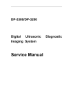
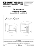
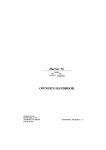
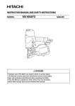
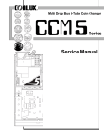
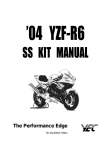
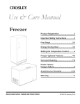
$1, $5 and Coupons BILL VALIDATOR
NBM-3000
Service Manual
R
SERIES
2
NBM-3000
SERIES
TABLE OF CONTENTS
Page
1. Outline ................................................................................................................................... 3
2. General Specifications ......................................................................................................... 4
* Detaild Specifications ........................................................................................................ 4
3. Quick Model Reference Chart for NBM-3000 Series .......................................................... 5
4. Installation ............................................................................................................................. 6
4-1 Installation ....................................................................................................................... 6
4-2 Setting Option Switches .................................................................................................. 6
4-3 Bill Insertion .................................................................................................................... 6
4-4 Bill Removal .................................................................................................................... 7
4-5 Diagnostic L.E.D. Indication ............................................................................................ 7
5. Component Description ...................................................................................................... 8
5-1 Identification of Components ........................................................................................... 8
5-2 Bill Path and Associated Operations ................................................................................ 9
6. Preventive Maintenance .................................................................................................... 10
7. Terminal Connection/Signal Conditions ..........................................................................
7-1 Terminal Conditions ......................................................................................................
7-2 I/O Circuit ......................................................................................................................
8. Connector and Wiring Diagram ........................................................................................
* Signals ...............................................................................................................................
* Wiring Diagram ..................................................................................................................
9. Bill Validator Components ................................................................................................
11
11
11
12
12
13
14
10. Disassembly and Assembly Procedure .......................................................................... 15
10-1 Disassembly and Assembly the Bill Validator Components ........................................... 15
10-2 Disassembly and Assembly the Housing Assy ............................................................... 18
10-3 Disassembly and Assembly the Chute (B) Assy ............................................................ 21
10-4 Disassembly and Assembly the Stacker Box ................................................................ 23
10-5 Disassembly and Assembly the Front Mask Assy ......................................................... 24
10-6 Disassembly and Assembly the Lift Base Assy ............................................................. 25
11. Exploded View and Parts List ......................................................................................... 28
11-1 NBM-3000 Series Composition .................................................................................... 28
11-2 Lift Base Assy............................................................................................................... 30
11-3 Housing Assy ................................................................................................................ 32
11-4 Chute (B) Assy .............................................................................................................. 34
11-5 Front Mask Assy ........................................................................................................... 36
11-6 Stacker Assy ................................................................................................................ 38
12. External View and Dimensions ....................................................................................... 40
12-1 NBM-3110, 3120 Series ............................................................................................... 40
12-2 NBM-3130, 3140 Series ............................................................................................... 41
12-3 NBM-3110-M, 3120-M Series ....................................................................................... 42
NBM-3000
SERIES
3
1. OUTLINE
The NBM-3000 Series Bill Validator has been developed based upon the M.D.B. communication
specifications. This validator is equipped with many added features, such as all plastic construction,
built-in antisalting system, accepts U.S. $1, $5 and coupons, vertical sensing, flash Rom
programming, unique bill stacking method and other exclusive features.
4
NBM-3000
SERIES
2. GENERAL SPECIFICATIONS Specifications and design are subject to change without notice.
Items
Currency Acceptance
Acceptance Rate
Cycle Duration
Accepts Bill
Validation Method and Conditions
*Shape Determined
*Pattern Determined
*Method of Validation
Escrow Function
Bill Pullback Prevention
Stacker Function
*Bill Storage Method
*Number of Bills Stored
NBM-3000 Series
US $1, $5, and coupons
(For use of coupons, check with the applicable specifications.)
90% or higher
1 Second approx. (time to identify vend signal)
Lengthwise, face up, two directions
(For coupons, lengthwise, fase up, one direction)
Yes (optical method)
Yes
Parallel use of magnetic and optical
Yes (single bill escrow)
Yes (shutter system)
Yes
Stacks upright in a row
Based on new bills:
Number of bills 700 70 bills
NBM
NBM-3110
Model
NBM-3130
NBM-3110-M
*Bill Removal
Number of Motors Used in Equipment
Operating Temperature Range
Insulation Resistance
Insulation Voltage Limit
Weight
In bundles
3 D.C. motors
+5OF ~ 140OF (-15OC ~ +60OC)
20 Mohm or higher
500 V for 1 min.
Power Supply
Rated Consumption/Operating Stale
34 V D.C.
NBM Model
Number of bills
Weight(Approx.)
NBM Model
Number of bills
Weight(Approx.)
NBM-3110
700 Stacker
2.31Lbs.(1.05kg)
NBM-3110-M
700 Stacker
2.80Lbs.(1.27kg)
400 50 bills
NBM-3120
NBM-3140
NBM-3120-M
NBM-3120
NBM-3130
NBM-3140
400 Stacker 700 Stacker 400 Stacker
2.20Lbs.(1.00kg) 2.43Lbs.(1.10kg) 2.34Lbs.(1.06kg)
NBM-3120-M
400 Stacker
2.71Lbs.(1.23kg)
10%
Standby
*1 Operation
*2 Max. Load
34 V D.C.
0.3 A or less
0.6 A or less
1.2 A or less
*1 Peak current when motor is operating: 1.6A, 20ms
*2 When motor is locked: Approx. 4s
The 34 V DC circuit of this product is provided with a 2.5 A fuse whose actual fusing
current is 5 A (200% of the rated value of 2.5 A). Therefore, when designing the power
supply of the vending machine, be sure that it can supply a current larger than 5.0 A.
Mounting Angle
Within 1O of vertical
* Detailed Specifications
(1) Identified as a Genuine Bill
When the authentic bill (US $1, $5 or Coupon) is inserted into the validator and is found to be
genuine, this information is sent to the main controller.
NBM-3000
SERIES
5
(2) Identified as a Counterfeit Bill
The inserted counterfeit bill is automatically returned.
* Bills 146mm or shorter and 166mm or longer.
* Bills having an unclear optical pattern.
(3) Inserted Bill Not Accepted
The bill validator is unable to accept bills in the following cases:
* When the stacker is determined to be full.
* When the validator develops a motor fault.
* When the validator develops a sensor fault. (Dirty)
* If a bill jam operation.
* When the bill is pulled from the validator during operation.
(4) When the Stacker is Full
The full signal is sent to the main controller when the stacker is full. To clear this signal; open the
stacker, remove the bills and close (safety switch ON/OFF) the stacker. This is transmitted to the
main controller.
3. Quick Model Reference Chart for NBM-3000 Series
NBM-3
0(see Table 3)
Reserved
(see Table 2)
(see Table 1)
Series
Model section
(Table 3)
(Table 1)
Code
Denomination
Code
Front mask
1
$1, $5 and Coupons
Non
Plastic
M
Metal
(Table 2)
Code
Front mask Stacker Box
1
(1)
2
(1)
3
4
Nunmber of bills
in Stacker
Front lamp
Front mask material
(See Table 3)
Yes
Plastic
No
Metal
Yes
Plastic
No
Metal
5.9 in
700
4.3 in
400
(2)
5.9 in
700
No
Plastic
(2)
4.3 in
400
No
Plastic
6
NBM-3000
SERIES
4. INSTALLATION
4-1 Installation
Bill Validator
After installing this unit into a vending
machine.
* Connect the validator to the vendor.
* Turn power on!
Vending Machine
CAUTION: Do not connect or disconnect
with power present.
4-2 Setting Option Switches
The option switches on the control board are as follows:
1 2
No.
Switch
1 Coupon select SW
ON
2
$5 Switch
ON/OFF
ON
OFF
ON
OFF
Details
Accept
Inhibit
Accept
Inhibit
4-3 Bill Insertion
Front Lamp
(Model: NBM-3110, 3120)
Insert
Insert
A U.S. $1 or $5 bill can be inserted black side
up, any lengthwise direction.
Coupons can only be inserted face up and
direction.
Black side up
* Front lamp indication (only for models with the front lamp)
The front lamp indicates the bill acceptance state in the following mode:
Front lamp flash/turn-off mode
Bill acceptance state
Flash/Turn-off mode
Acceptance enable state
Flash
Repeat the cycle consisting of lit (0.3 s), turned off (0.3 s), lit (0.3 s), and turned off (0.7 s).
Acceptance disable state
Turn off
NBM-3000
SERIES
4-4 Bill Removal
To Remove Bills: Lift the white latch upwards to open the stacker lid.
The stacker assy is now removable from the validator.
Remove Bills
To Reinstall Stacker: Insert the bottom of the stacker box into the
validator and close the stacker lid.
Warning: Be sure to reinstall the stacker into its original
position!
4-5 Diagnostic L.E.D. Indication
A diagnostic L.E.D. is placed on the back of the validator. The L.E.D. indicates the status or abnormal
condition of the bill validator.
L.E.D. Diagnostics
L.E.D. Mode
OFF
ON (steady)
Single Flash
Double Flash
Triple Flash
Four Flash
Five flashes or more
L.E.D. Diagnostics
Bill validator status
No power
Normal Operation
Stacker Full
Stacker Incorrectly Installed
Cleaning of Sensors Require
Disabled from Controller
Disabled
7
8
NBM-3000
SERIES
5. COMPONENT DESCRIPTION
5-1 Identification of Components
Bill Stacker
Sefaty Switch
Front Mask (1)
Housing
Stacker Latch
Front Lamp
(Model: NBM-3110, 3120
only for models with the front lamp)
Cam Assy
Stack Plate
Lift Base Assy
Belt
Stack Lever
Prevention (of hanging)
Lever
Stack Roller
Chute (B) Assy
Control Harness
NBM-3000
SERIES
9
5-2 Bill Path and Operations
(1) When a bill is inserted into
the opening face up either direction, the validator automatically draws the bill in for
validation.
Stack Motor
Carrier Motor
Drum Ass'y
Stack Plate
(2) If the bill is determined to be
authentic, it is temporarily
held in the escrow mode.
Upon receving of the stack bill
signal from the main controller, the bill is stacked.
(3) If the bill is found to be counterfeit, it will be returned automatically.
When a bill is inserted, the carrier motor rotates
and the bill is drawn into the validator.
The information detected by the photo sensor
and magnetic head is sent to the control board
for discrimination.
If the bill is validated to be authentic, it is temporarily held in the escrow mode.
Upon receipt of the stack bill signal from the
main controller, the bill is stacked.
If the bill is counterfeit the carrier motor rotates
in reverse and returns the bill.
Stacker Lever
Stacker
Prevention (of hanging) lever
Stacker Roller
P2 Lever
Magnetic Head
Shutter Switch
Inlet Lever
Photo Sensors
Shutter Lever
10
NBM-3000
SERIES
6. PREVENTIVE MAINTENANCE
The validator bill path can become contaminated by dirty bills, dust, moisture or other foreign
matter. If the L.E.D. flashes three times, the validator sensor has been heavily contaminated;
clean the sensor. It is strongly recommended to clean the validator every one to three months
depending on the amount of use or its environment.
* Cleaning the Stacker
(1) Lift the white latch upwards to open the stacker lid.
Stacker box is now removable from the validator.
(2) Clean the stack drums and carrier belts with a
soft lint free cloth.
Drum Ass'y
Belt
* NEVER use alcohol, benzene, thinner or anything of this nature for cleaning the carrier belt.
* Flashing L.E.D.
When the validator sensor needs to be cleaned, the L.E.D.
flashes three times in succession. Cleaning should be done
as shown below:
* Opening of the Chute / Cleaning of the Bill Path
Squeeze both latches inwards (as shown below) to open
the chute.
Remove the chute by pulling upward and out (as shown
below).
* Remove debris or foreign obstacles.
* Clean the magnetic and optical sensor sections
with a cotton swab or soft cloth. Also, clean
the carrier section including the chute, rollers
and belts, using a soft cloth.
Reinstall the chute in reverse order.
NBM-3000
SERIES
11
* Clean bill insertion opening.
* Clean the magnetic and optical sensors.
* NEVER use alcohol, benzene, thinner or anything of this nature for cleaning the carrier belt.
7. Terminal Connection/Signal Conditions
7-1 Terminal Conditions
* 6-pin Connector
Receptacle Housing:
Socket Terminal:
Plug Housing :
Pin Terminal :
Terminal No.
1
2
3
4
5
6
Signal Name
Power Supply
Power Supply
N. C.
Main Control Reception
Main Control Transmission
Common Communications
Molex 5557-06R
Molex 5556T
Molex 5559-06P
Molex 5558T
Input/Output
Signal Conditions
Input
+ DC 34V (usually supplied)
Input
- DC 34V (usually supplied)
Output
Input
Input
Transmission Data Output Signal.
Reception Data Input Signal.
Common Transmission Line.
Note: Input/Output is relative to the Validator.
7-2 I/O Circuit
(1) Input Circuit
6P Connector
(2) Output Circuit
6P Connector
R1, R3 : 270 ohm
PC1 : Sharp PC702V3 or equivalent
D1 : Toshiba 1SS181 or equivalent
C1 : 2200pF
R2 : 470 ohm
PC2 : Sharp PC702V3 or equivalent
D2 : Toshiba 1SS181 or equivalent
12
NBM-3000
SERIES
8. CONNECTOR AND WIRING DIAGRAM
* SIGNALS
J3 5Pin Post
Voltage
Stand-by (V)
Voltage
during
Opration (V)
Output + 15V
15
15
Output + 12V
12
12
Pin
No.
Wire
Color
Input/
Output
1
White
2
White
Signal
3
White
Input Shutter sensor Close
5 (approx)
0
4
White
Input Shutter sensor Open
5 (approx)
0
5
Red
0
0
Ouput GND
J4 3Pin Post
1
Brown
2
Red
3
(non the front lamp)
Input Entrance sensor P1RL emitting
1.2 (approx) 1.2 (approx)
Input Entrance sensor P1RL
5 (approx)
0
0
0
15 (approx)
0
-
-
Orange Output GND
J5 3Pin Post
1
Brown
2
-
3
Output Carrier motor (CW rotation)
-
Orange Output Carrier motor (CCW rotation) 15 (approx)
0
J6 3Pin Post
1
Brown
2
-
3
Output Stacker motor (CW rotation)
0
15 (approx)
-
-
0
0
12 (approx)
0
Output Shutter motor (CCW rotation) 12 (approx)
0
-
Orange Output Stacker motor (CCW rotation)
J7 2Pin Post
1
Brown
2
Red
Output Shutter motor (CW rotation)
J8 2Pin Post
J1 5Pin Post
Voltage
Stand-by (V)
Voltage
during
Opration (V)
Input Power Supply 34 VDC
34
34
Input Power Supply GND
0
0
5
0
Input Main Control Transmission
0
5
Input Common Communications
0
0
Pin
No.
Wire
Color
Input/
Output
1
Red
2
Black
3
Green
4
Blue
5
White
Signal
Output Main Control Reception
J2 8Pin Post
1
White
2
White
3
Output GND
1
Brown
2
Red
Input Carrier switch
Output GND
5 (approx)
0
0
0
0
5 (approx)
0
0
J9 2Pin Post
1
Brown
2
Red
Input Safety switch
Output GND
J10 4Pin Post
1
Black
2
White
3
Red
4
Blue
Output Emitting sensor (LED) Anode 6.0 (approx) 1.2 (approx)
Input Emitting sensor (LED) Cathode
0
8.2 (approx)
Input Moniter lamp
0
13.2(approx)
15
15
0
0
Output + 15V
J11 8Pin Post
0
0
1
-
Input Magnetic head HD
5 (approx)
5 (approx)
2
-
Input TXD Signal
5 (approx)
0
White
Input Light detector PXLS
5 (approx)
0
3
-
Input RXD Signal
5 (approx)
0
4
White
Input Light detector PXL
5 (approx)
0
4
-
Input RESET Signal
0
5 (approx)
5
White
Input Light detector PXC
5 (approx)
0
5
-
Input Vin (+ 5V)
5
5
6
White
Input Light detector PXR
5 (approx)
0
6
-
Input Vpp (+ 12V)
12
12
7
White
Input Light detector PXRS
5 (approx)
0
7
-
Input MD1 (+ 12V)
12
12
8
Red
5
5
8
-
0
0
Output +5 V
Output Power Supply (GND)
Output Power Supply (GND)
Signal Name
Power supply 34V DC
Power supply GND
N. C.
Main control Reception(RXD)
Main control Transmission(TXD)
Common communications(COM)
No.
1
2
3
4
5
6
1
White
2
Red
PXR
PXC
PXL
・
・
SW2
SW1
HD
・・・・
PXRS
PXLS
Amp. Board
J2
J1
GND
SHTOPN
SHTCLS
+12V
+15V
+5V
PXRS
PXR
PXC
PXL
PXLS
HD
GND
Red
White
White
White
White
Red
White
White
White
White
White
White
White
3
Black
4
Yellow Output FTLP
Output GND
Input Entrance sensor P1RL
2
3
P1RL Emitting
P1RL
GND
Brown
Red
Orange
・
Front lamp
・
P1RL
Sensor board Entrance
P1RL Emitting
P1RL
GND
FTLP
White
Red
Black
Yellow
NBM-3110, 3120 Series (only for models with the front lamp)
P1RL
1
6
5
6
5
1
2
2
3
4
3
4
1
2
1
3
2
3
1
1
2
1
2
5
4
3
3
5
2
1
2
1
4
3
3
4
7
7
4
8
8
7
6
5
4
3
2
8
Signal Name
Terminal No.
Power Supply (GND)
1
TXD Signal
2
RXD Signal
3
RESET
Signal
4
Vin (+ 5V)
5
Vpp (+ 12V)
6
MD1 (+ 12V)
7
Power
Supply (GND)
8
J4
J4
J3
J2
J11
J1
Control Board
J10
J9
J8
J7
J6
J5
1
2
3
4
1
3
4
2
1
2
1
2
2
2
1
2
1
2
1
3
3
1
1
2
1
3
3
2
1
2
1
2
Brown
Black
White
Red
Blue
Anode
Cathode
MONLP
+15V
COM
COM
Safety SW
Carrier SW
Shutter Motor
Stack Motor
Carrier Motor
PXRS
PXR
PXC
PXLS
(Monitor lamp)
PXL
Sensor Board Light emitting
NO
NC
NO
NC
MO
MO
MO
Note
1. Line color may change.
2. This drawing represents the wait state.
Brown
Red
Brown
Red
Brown
Red
Orange
Brown
Orange
* WIRING DIAGRAM
Sensor board Entrance
5
5
1
3
4
3
4
1
2
1
2
8P Posts
JAE IL-S-8P-S2L2-EF(White)
Red
Black
Green
Blue
White
NBM-3130, 3140, 3110-M, 3120-M Series (non the front lamp)
Signal Name
Power supply 34V DC
Power supply GND
N. C.
Main control Reception(RXD)
Main control Transmission(TXD)
Common communications(COM)
6P Plug housing: Molex 5559-06P
Terminal: Molex 5558T
No.
1
2
3
4
5
6
*MDB Harness ASSY
6P Receptacle housing: Molex 5557-06R
Terminal: Molex 5556T
NBM-3000
SERIES
5 (approx)
0
0
0
13
J4 3Pin Post (only for models with the front lamp)
Input Entrance sensor P1RL emitting1.2 (approx) 1.2 (approx)
14
NBM-3000
SERIES
9. BILL VALIDATOR COMPONENTS
Housing Assy
Stacker Box Assy
Lift Base Assy
Front Mask Assy
Drum Assy (R)
Control Board Assy
Drum Assy (L)
Chute (B) Assy
Drum Guide (R)
1
Drum Guide (L)
Output Bearing (1)
Screws
2
3
1. Self-Tapping Screw (+)Pan-head 3 x 8
2. Self-Tapping Screw (+)Pan-head 3 x 10
3. Self-Tapping Screw (+)Flush-head 3 x 8
NBM-3000
SERIES
15
10. DISASSEMBLY AND ASSEMBLY PROCEDURES
Disassembly the bill validator in the order written, reassembly in reverse order.
10-1Disassembly and Assembly of the Bill Validator Components
1. Stacker Box Assy
Main Latch
Removal:
1. Lift the white latch upward to open the
stacker lid.
2. Stacker box is now removable from the
validator.
Installation:
Reinsert the bottom of the stacker box into the
validator and close the stacker lid.
Installation:
Stacker Box Assy
Figure 1
2. Chute (B) Assy
Removal:
1. Squeeze both latches inward to open the
chute.
2. Pull the chute outward and remove.
Installation:
In reverse order.
Chute (B) Assy
Figure 2
3. Front Mask Assy
Removal:
Front Mask Assy
1. Remove the pan head tapping screws
(M3x10).
2. Pull the front mask assembly toward you,
slightly push it down and remove.
Installation:
In reverse order.
Figure 3
16
NBM-3000
SERIES
4. Control Board Assy
Two Connectors
Removal:
1. Remove the two connectors from the back
of the control board assy.
2. Unhook the four latches on the housing and
pull the control board assy out toward you.
3. Remove the eight connectors from the front
of the control board assy and remove the
board.
4. Cut the harness tie wrap and remove the
chute (B) harness assy.
Installation:
In reverse order.
Control Board Ass'y
Eight Connectors
Note: When reconnecting the connectors
to the board, make sure they are fully
inserted into the board. Failure to do
so may cause malfunctions.
Figure 4
5. Drum Assy (R), (L) and Drum Guide
(R), (L)
Removal:
1. Remove the flat-head tapping screws (M3x8)
on both sides of the housing and two panhead tapping screws (M3x8) inside of the
housing.
2. Push the two alignment pins of the drum
guides from the housing holes and remove
them together with the drums. The alignment
pins are firmly fitted in the housing, be careful when removing them.
Installation:
Note: Be careful not to mistake the right
drum (R) for the left drum (L) or vice
versa.
Drum Guide (R)
Drum Assy (R)
Installation:
1. Position the drums on to the drum guides
and insert the drums and drum guides onto
the cam of the stack output shaft.
2. Install the drum guides by inserting the alignment pins into the housing.
3. Make sure the stacker lever is positioned
inside each drum.
Drum Guide (L)
Drum Assy (L)
Figure 5
NBM-3000
SERIES
17
6. Lift Base Assy and Output Bearing (1)
Removal:
1. Remove the two flat head tapping screws
(M3x8) from both sides of the housing and
two pan-head tapping screws (M3x8) on the
lift base.
2. Pull out the bottom of the lift base assy toward you or to the stack side of the housing. The belts on the lift base assy may be
hooked on the mountig posts; unhook the
belt.
3. When pulling out the lift base assy to the
position as shown in Figure 6, hold the gear
section and remove the right side of the assembly first. Pull the left side out (that is
engaged with the left output shaft) toward
you. The output bearing (1) located on the
left side needs to be removed together with
the lift base.
Left Side
Right Side
Note: When pulling out the bottom of the
lift base assy toward you, be sure not
to pull it up excessively or the engaging gears may be damaged.
Outout Bearing (1)
Installation:
1. Assemble the output bearing (1) onto the
left side of the output shaft on the lift base
assy. Insert the left side together with the
bearing into the housing.
2. Insert the right side of the lift base output
shaft into the housing. Unhook the belts from
under the mounting post on the back side
of the housing.
3. Insert the bottom of the lift base assy into
the housing by spreading the sides of the
housing.
4. Install the two pan-head tapping screws
(M3x8) to the lift base and the two flat-head
tapping screws (M3x8) onto the sides of the
housing.
Note: When installing the lift base assy, be
careful not to let the output bearing
(1) and the idling roller slip off. Also
make sure to unhook the belts from
the mounting post before inserting
the assembly. Failure to do so may
result in damage to the belts.
Lift Base Assy
Installation:
Figure 6
18
NBM-3000
SERIES
10-2 Disassembly and Assembly of the Housing
1. Carrier Gear Cover
Removal:
1. Remove the two flat head tapping screws
(M3x8) from the carrier gear cover.
2. Unlatch the two tabs inside the housing with
a flat-head screwdriver and remove the
cover.
Tabs
Installation:
In reverse order.
Carrier Gear Cover
Figure 1
2. Carrier Gears, Bearings, and Pulse
Shaft Assy
Removal:
The carrier gears, bearings and pulse shaft assembly can be disassembled as shown in Figure 2.
Installation:
Note: When removing the gears inserted
into the shaft, take care not to damage them.
Installation:
When assembling, be careful not to damage
the gears or forget their positions.
Figure 2
3. Carrier Motor and Harness Assy
Removal:
1. Remove the two pan-head screws (M3x4).
2. Remove the carrier motor and harness assembly.
Installation:
In reverse order.
Carrier Motor Harness Assy
Figure 3
NBM-3000
SERIES
4. Stack Gear Cover
19
Stack Gear Cover
Removal:
1. Unlatch the two tabs on the stack side of the
housing.
2. Pull upward and remove the cover.
Installation:
1. Latch the two tabs (on the front side) of the
housing.
2. Push the cover in place.
Note: Be careful not to pry the tabs aggressively.
Two Latctes
Figure 4
5. Stack Gears and Shaft
Removal:
Stack Output Gear
(For Drum Assy)
The gears and shaft can be disassembled as
shown in Figure 5.
Note: When removing the gears from the
shaft, be careful not to damage them.
Please pay close attention to the position of the stack output gears.
Stack Output Gear
(For Drum Assy)
Installation:
Installation:
When installing the gears, the cam shaft of the
two stack output gears should be oriented in
the same position as they were prior to removal.
Note: If the cam shafts are not positioned
correctly, the drum assemblies (R)
and (L) cannot be installed.
Figure 5
6. Stack Motor and Harness Assy
Removal:
1. Remove the two pan-head screws (M3x4)
from the stacker motor.
2. Remove the stack motor and harness assy.
Installation:
Stack Motor and
Harness Assy
In reverse order.
Figure 6
20
NBM-3000
SERIES
7. Main Latch, Shaft and Spring
Removal:
1. Pull the shaft out by pressing one side.
2. Remove the stacker latch, shaft and spring.
Note: The spring is under tension, be careful during disassembly and assembly.
Main Latch
Installation:
In reverse order.
Figure 7
8. Carrier Switch and Harness Assy
Removal:
Carrier Switch and Harness Assy
1. Remove the harness from the housing.
2. Pull the switch assy upward toward you and
remove.
Installation:
In reverse order.
Note: Be sure to route the harness as it was
prior to removal.
Figure 8
9. Safety Switch and Harness Assy
Removal:
Safety Switch and Harness Assy
1. Remove the harness from the housing.
2. Unhook the right and left latches and pull
the switch toward you.
Installation:
In reverse order.
Note: Be sure to route the harness as it was
prior to removal.
Figure 9
10. M.D.B. Harness Assy
Removal:
Installation:
M.D.B. Harness Assy
Cut the harness tie wrap from the M.D.B. Harness Assy and the housing.
Installation:
Reinstall the M.D.B. Harness Assy back into
place, and fasten the harness with the tie wrap
as illustrated in Figure 10.
Figure 10
NBM-3000
SERIES
21
10-3Disassembly and Assembly of the Chute (B) Assy
1. Chute (B) Cover
Four Latches
Removal:
1. Unhook the four latches on the back of the
chute (B).
2. Slide the whole cover toward you and unhook the lower two latches to remove the
cover.
Installation:
In reverse order.
Chute (B) Cover
Figure 1
2. Chute (B) Latch and Spring
Removal:
1. Remove the right and left ends of the spring
from the chute (B) latches.
2. Remove the latches.
Installation:
Chute Latch Spring
In reverse order.
Note:
Install the components in the reverse order of the removal procedure.
Chute (B) Latch
Installation:
Figure 2
3. PX L.E.D. Board Assy
Removal:
1. Unhook the four latches on the board.
2. Cut the tie wrap and remove the PX L.E.D.
board assy.
PX L.E.D. Board Assy
Installation:
In reverse order.
Figure 3
22
NBM-3000
SERIES
4. Rollers, Brackets, Shafts and Springs
Removal:
1. Unhook the two latches on the first-rollerbrackets by inserting a small screwdriver.
2. Remove the rollers, springs and shafts of
the first-roller-brackets.
3. Unhook the four latches on the second-rollerbrackets by inserting a small screwdriver
from the opposite side.
4. Remove the rollers, springs and shafts of
the second-roller-brackets.
5. Remove the end of the carrier roller spring
from the guide gutter and unlatch the convex part. The spring can now be removed.
6. Remove the carrier roller and shaft.
7. Confirm that the disassembled rollers, brackets, shafts and springs are as shown in Figure 4.
Roller Shaft, Roller (1), Roller Spring (1), Roller Shaft Bracket (1)
Roller (1)
Roller Shaft
Installation:
Roller Spring (1)
Install the components in the reverse order of
the removal procedure by referring to Figure 4.
Note:
1. Special care should be taken with the
springs as they may have different
strengths even if their shapes are the
same. DO NOT MIX THE SPRINGS!
2. Be sure to replace the carrier roller
springs as they were prior to removal.
3. If the springs are wrongly oriented, the
validator may not perform correctly. Take
notice of the proper posistion of each
part. DO NOT MIX THEIR LOCATION!
Roller Shaft
Bracket (1)
Pinch Roller Shaft, Roller (1), 2nd Roller Spring,
2nd Roller Shaft Bracket
2nd Roller Spring
Pinch Roller Shaft
Roller (1)
2nd Roller Shaft Bracket
Carrier Roller Spring
Roller (1)
Installation:
Roller Shaft
Figure 4
NBM-3000
SERIES
23
10-4Disassembly and Assembly of the Staker Box
1. Stacker and Stacker Box (Upper or
Lower)
Removal:
1. Unhook the right and left stacker latches on the
top. Insert a flat-head screwdriver into the mating surface of the box to open the surface.
2. Disassemble he stacker box guide from the
stacker box.
Note:
Do not apply excessive force to separate
the stacker box from the stacker guide.
Stacker Box Guide
Installation:
1. Mate the stacker with the stacker box guide.
2. Assemble them back into place.
Stacker Box
Figure 1
2. Stack Plate, Stacker Box and Pressure Spring
Stacker Box
Removal:
1. Unhook the latch on the spring and remove
the plate and spring.
Installation:
In reverse order.
Stack Plate
Press Spring
Figure 2
3. Stack Levers and Spring
Removal:
Stack Lever
1. Unhook the latch shown in Figure 3 with a
flat-head screwdriver.
2. Pull the lever upward toward you, unhook the
latch on the other side and remove the spring.
Installation:
1. Install the spring onto the stack lever and
hook the end of the spring into the slot. Now
push the stack lever into the hole.
2. Push the other end of stack lever into the
other hole.
Note:
Be careful not to mistake the right side (R)
for the left side (L) or vice versa when installing the lever and the spring.
Stack Lever Spring
Figure 3
24
NBM-3000
SERIES
4. Stack Cover, Roller, Bracket, Prevention (of hanging) Lever and
Spring
Removal:
1. Unhook the two latches in front of the stack
cover with a flat-head screwdriver.
2. Unhook the four latches while lifting the
stacker cover toward you.
3. Remove the cover and then individual parts
as shown in Figure 4.
Prevention (of hanging)
Lever (2)
Prevention (of
hanging) Lever (1)
Prevention Lever Spring (2)
Prevention Lever Spring (1)
Installation:
In reverse order.
Stacker Cover
Note:
Individual parts are small, be careful not to
lose or damage them.
Installation:
Stack Roller
Roller Spring (1)
Stack Roller Bracket
Figure 4
10-5Disassembly and Assembly of the Front Mask Assy
Removal:
1. Remove the pan-head tapping screw (M3x8).
2. Remove the mask from the metal mask base.
Installation:
In reverse order.
Front Mask
Mask Base
Figure 1
NBM-3000
SERIES
25
10-6Disassembly and Assembly of the Lift Base Assy
1. Mask Chute (Upper) Assy
Removal:
Unhook the two latches with a flat-head screwdriver and pull the upper mask chute assembly toward you.
Installation:
In reverse order.
(1) Inlet Sensor Board Assy
Removal:
Remove the two flat-head tapping screws
(M3x8).
Mask Chute (Upper) Assy
Inlet Sensor Board Assy
E-ring
Inlet Lever
(2) Inlet Lever, Shaft and Spring
Removal:
Inlet Lever Spring
Inlet Lever Shaft
1. Remove the shaft from the chute with a flathead screwdriver.
2. Remove the inlet levers and springs from
the shaft.
Front Lamp
Installation:
Assemble the lever and spring onto the shaft
and install them into the chute.
Note:
Adjust the position of the springs so that
the inlet levers move smoothly. Do not increase spring tension.
Figure 1
2. Idler, Shaft, Springs and Belts
Idler Spring
Removal:
Belts
1. Grip the springs with a pair of pliers and remove then from the shaft. Do not overextend the springs.
2. Spread the lift base housing case apart just
enough to remove the shaft and idlers. Do
not over stretch the case.
3. Remove the shaft and belts.
4. Remove the E-rings to remove the idlers.
Installation:
In reverse order.
Note:
The spring need to be removed when the
head bracket assy is removed. Do not over
stretch the springs.
Idler
Idler Shaft
Figure 2
26
NBM-3000
SERIES
3. Chute (A), Shutter Motor Assy, Shutter
Gears and Carrier Pulley Assy
Pulley (1)
Lift Base
Removal:
1. Unhook the two latches and pull the chute
(A) down.
2. Remove the two carrier pulleys and two shutter gears. Note their positions prior to removal.
3. Unhook the four latches on the shutter motor assy and pull out the assembly.
Latches
Shutter
Gear
Shutter Motor Assy
Installation:
In reverse order.
Note:
The shutter gears should be oriented in the
same position as prior to their removal.
Figure 3
4. Head Bracket Assy, Shutter and Carrier Pulley Assy
Head Bracket Assy
Removal:
1. Remove the two pan-head tapping screws
(M3x8).
2. Remove the head bracket assy.
3. Remove the shutter and two carrier pulleys.
Installation:
In reverse order.
Note:
Be sure to install the carrier pulleys prior
to installing the shutter.
Carrier Pulley (2)
Shutter
Figure 4
5. P2 Lever, Shaft and Spring
Removal:
1. Push the end of the shaft with a thin blade
screwdriver first and remove the shaft.
2. Remove the P2 lever and the spring.
Installation:
In reverse order.
P2 Lever Spring
Note:
Do not increase spring tension.
P2 Lever Shaft
P2 Lever
Figure 5
NBM-3000
SERIES
6. Stacker Chute, Stacker Lever, Drive
Shaft, Carrier Pulley (1) Assy, Stacker
Chute Spring, Drive Bearing (2) and
Idler Shaft
27
Carrier Pulley (1) Assy
Drive Shaft
Bearing (2)
Removal:
1. Pull he carrier pulley (1) assy off of the drive
shaft.
2. Remove the drive bearings (2) and shaft.
3. Push the end of the lift base shaft (2) with a
thin blade screwdriver and remove the shaft.
4. Remove the E-ring and pull out the lift base
shaft (1).
5. Remove the stacker chute spring.
6. Remove the stacker chute and stacker lever.
Lift Base Shaft (2)
Installation:
1. Assemble the stacker lever to the stacker
chute, and then insert the shaft before installing the E-ring.
2. Hook the stacker chute spring onto the shaft.
3. Install them into the lift base and insert the
lift base shaft.
Align the shaft groove with the latch on the
lift base.
4. Assemble the carrier pulley (1) assy and
bearing to one side of the drive shaft before
inserting them into the lift base. Then install
the bearing and the carrier pulley (1) to the
other side.
5. Hook the stacker chute spring onto the spring
tab of the lift base.
Lift Base Shaft (1)
Stacker Chute Spring
Stacker Lever
Stacker Chute
Figure 6
28
NBM-3000
SERIES
11. EXPLODED VIEW AND PARTS LIST
11-1. NBM-3000 SERIES
5
6
4
11
20
1
19
2
8
17
9
10
18
19
7
15
21
12
14
3 13
21
15
20
14
16
NBM-3000
SERIES
PART NO.
INDEX
NO. Parts No.(10 digits) Draw No.
DESCRIPTION
QTY
REMARKS
29
MODELS
0
0000436010
043601
NBM-3110 Bill Validator
1
Mask 1-700 Stacker
0
0000436020
-
NBM-3120 Bill Validator
1
Mask 1-400 Stacker
0
0000436030
-
NBM-3130 Bill Validator
1
Mask 2-700 Stacker
0
0000436040
-
NBM-3140 Bill Validator
1
Mask 2-400 Stacker
0
0000436050
043605
NBM-3110-M Bill Validator
1
Mask M-700 Stacker
0
0000436060
043606
NBM-3120-M Bill Validator
1
Mask M-400 Stacker
1
8210010014
436103
Lift Base Assy
1
Old Version (obsolete)
NBM-3110, 3120
1
8210010024
-
Lift Base Assy (2)
1
1
8210010034
-
Lift Base Assy (3)
1
Front Lamp Type
NBM-3110, 3120
2
8510010011
436104
Housing Assy
1
3
8212010010
436105
Shute (B) Assy
1
4
8110010010
436106
Front Mask (1) Assy
1
Old Version (obsolete)
NBM-3110, 3120
4
8110010011
-
Front Mask (1) Assy
1
Front Lamp Type
NBM-3110, 3120
5
8110010020
-
Front Mask (2) Assy
1
6
8030010010
-
Front Mask-Metal Assy
1
Metal Old (obsolete)
6
8030010020
-
Front Mask-Metal Assy
1
Front Lamp Type
NBM-3110-M, 3120-M
7
8030010030
-
700 Stacker Box Assy-SL
1
Decals Included
NBM-3110, 3130
8
8030010040
-
400 Stacker Box Assy (2)-SL
1
Decals Included
NBM-3120, 3140
9
8461010010
436117
Drum (R) Assy
1
10
8461010020
436118
Drum (L) Assy
1
11
86X0010084
-
Control Board Assy
1
11
86X0010094
-
Control Board Assy (2)
1
12
8461210060
436416
Drum Giude (R)
1
13
8461210070
436417
Drum Giude (L)
1
14
3912931001
-
StackerDecal
1
15
3912931010
436532
Stacker Lid Decal
1
16
3911950140
-
Model/SerialPlate
1
17
3532030090
476478
Output Shaft Bearing (1)
1
18
3913950300
-
Flash ROM Seal
1
19
3253030810
904315
Self-TappingScrew
4
(+)Pan-head 3 x 8
20
3253031010
904316
Self-TappingScrew
4
(+)Pan-head 3 x 10
21
3257030810
904602
Self-TappingScrew
2
(+)Flush-head 3 x 8
NBM-3130, 3140
NBM-3130, 3140
NBM-3110-M, 3120-M
Data Stored Function
Front Lamp Type
Data Stored Function
Not for resale
Option
30
NBM-3000
SERIES
11-2. Lift Base Assy
Old Version
2
1-5
27
1-6
1-3
1-4
1-2
1-4
1-2
22
4
4
14
22
1-1
23
6
1
24
9
15
5
5
26
24
16
26
15
19
20
7
19
11
13
5
5
10
New Version
23
25
1'-5
1'-7
18
17
1'-6
21
1'-3
1'-4
New Version with Front Lamp
1'-4
1'-2
1"-5
3
1'-2
1'-7
12
1"-7
1"-6
1"-3
1'-1
1''-4
8
1"-2
1"-7
1'
1"
1"-1
1"-4
1"-2
NBM-3000
SERIES
PART NO.
INDEX
NO. Parts No.(10 digits) Draw No.
0
8210010014 436103
0
8210010024
0
8210010034
1
8130010013 436108
1
8130010023
1-1
8111210023 436421
1-1
8111210042
1-2
8132105010 468412
1-3
3821030650 436505
1-4
3814010890 436515
1-5
3253030810 904315
1-6
81X0010011
1'
8130010013
1'
8130010023
1'-1
8111210023 436421
1'-1
8111210042
1'-2
8132105010 468412
1'-3
3822030230
1'-4
3814010890 436515
1'-5
3253031010
1'-6
81X0010012
1'-7
3551020010
1"
8130010031
1"-1
8111210023
1"-2
8132105010 468412
1"-3
3822030230
1"-4
3814010890 436515
1"-5
3253031010
1"-6
81X0010021
1"-7
3551020010
2
8F10010011 436109
3
8143010040
4
3693220020 436115
5
3731030040 436116
6
8211110023 436405
7
8461210050 436403
8
8211110012 436401
9
8143310010 436411
10
8222110010 436425
11
8461210080 436426
12
3694220020 436431
13
3821020270 436530
14
3821040300 436510
15
3831220560 436504
16
3821040290 436506
17
3822040260 436508
18
3821030660 436509
19
3813010570 436518
20
3813010580 436521
21
3813010640 436529
22
3532040040 435509
23
3711180010 927174
24
3731012050 479418
25
3551020010 907403
26
3551030010 907404
27
3253030810 904315
DESCRIPTION
Lift Base Assy
Lift Base Assy (2)
Lift Base Assy (3)
Mask Chute (Upper) Assy
Mask Chute (Upper) (2) Assy
Mask Chute (Upper)
Mask Chute (Upper) (2)
Inlet Lever
Inlet Lever Shaft
Inlet Lever Spring
Self-TappingScrew
Inlet Sensor Board Assy
Mask Chute (Upper) Assy
Mask Chute (Upper) (2) Assy
Mask Chute (Upper)
Mask Chute (Upper) (2)
Inlet Lever
Inlet Lever Shaft (2)
Inlet Lever Spring
Self-Tapping Screw
Inlet Sensor Board Assy
E-ring
Mask Chute (Upper)(3) Assy
Mask Chute (Upper)(3)
Inlet Lever
Inlet Lever Shaft (2)
Inlet Lever Spring
Self-Tapping Screw
Inlet Sensor Board (2) Assy
E-ring
Head Bracket Assy
Shutter Motor Assy
Carrier Pulley (1) Assy
Carrier Pulley (2) Assy
Lift Base
Stacker Chute
Chute (A)
Shutter
P2 Lever
Stacker Lever
Shutter Gear
P2 Lever Shaft
Drive Shaft
Idler
Idler Shaft
Lift Base Shaft (1)
Lift Base Shsft (2)
Idler Spring
P2 Lever Spring
Stacker Chute Spring
Drive Bearing (2)
Belt
Pulley (1)
E-ring
E-ring
Self-TappingScrew
QTY
REMARKS
1
1
1
1
1
1
1
2
1
2
2
1
1
1
1
1
2
1
2
2
1
2
1
1
2
1
2
2
1
2
1
1
2
4
1
1
1
1
1
1
2
1
1
2
1
1
1
2
1
1
2
2
2
1
2
1
Includes 1~27
Includes 1~27
Front Lamp Type
Includes 1-1~1-6
Includes 1-1~1-6
(+)Pan-head 3 x 8
Obsolete
Includes 1'-1~1'-7
Includes1'-1~1'-7
MODELS
NBM-3110, 3120
NBM-3130, 3140
NBM-3110, 3120
NBM-3110, 3120
NBM-3130, 3140
NBM-3110, 3120
NBM-3130, 3140
NBM-3110, 3120
NBM-3130, 3140
NBM-3110, 3120
NBM-3130, 3140
(+)Pan-head 3 x 10
Includes 1"-1~1"-7
(+)Pan-head 3 x 10
Front Lamp Type
B180MXL3.2
(+)Pan-head 3 x 8
NBM-3110, 3120
NBM-3110, 3120
31
32
NBM-3000
SERIES
11-3. Housing Assy
10
13
4
12
12
7
6
7-2
24
24
7-1
25
21
26
28
25
29
27
15
3
13
29
11
16
20
30
5
2
9
18
12
23
14
22
17
1
8
32
31
NBM-3000
SERIES
PART NO.
INDEX
NO. Parts No.(10 digits) Draw No.
0
8510010010 436104
0
8510010011
1
8241010010 436101
1-1
1-2
1-3
1-4
2
8241010020 436102
2-1
2-2
3
8F31010010 436111
3-1
3-2
4
8441010010 436112
4-1
4-2
5
8472010010 436113
5-1
5-2
6
8462010010 436114
6-1
6-2
7
5831001030
7-1
7-2
8
4116000030 436311
9
8511110011
9
8511110015
10
8514110020 436419
11
8514110031 436420
12
3624220020 210497
13
3612230050 461455
14
3624140010 476499
15
8231304010 461413
16
3532020040 476917
17
3532030090 476478
18
3532G10010 436538
19
20
3614220070
21
3821030570 735513
22
3821E20051 436511
23
3821E30030
24
3615220040 436429
25
3694220010 436430
26
8512110010 436441
27
3821030200 461540
28
3814010940 436526
29
3211030410 900006
30
3257030810 904602
31
4774900010 994047
32
4774900050 927039
DESCRIPTION
QTY
HousingAssy
HousingAssy
Output Shaft Assy
Output Gear
Gear (2)
Bearing (3)
Output Shaft
PulseShaftAssy
PulseShaft
1stGear
Carrier Motor Assy
Motor
Carrier Motor Harness Assy
Stack Motor Assy
Motor
Stack Motor Harness Assy
Safety Switch Assy
PushSwitch
Safety Switch Harness Assy
Carrier Switch Assy
Micro Switch
Carrier Switch Harness Assy
Gear (A) Comp.
Gear (A)
Insert Pinion
M.D.B. Harness Assy
Housing
Housing
Stack Gear Cover
Carrier Gear Cover
2ndGear
Carrier Motor Pinion
2nd Gear (2)
Tachometer
Pulse Bearing (2)
Output Bearing (1)
Bearing (2)
1
1
1
1
1
1
1
1
1
1
1
1
1
1
1
1
1
1
1
1
1
1
1
1
1
1
1
1
1
1
3
2
1
1
1
1
1
Carrier Gear (2)-M
Head Roller Shaft
GearShaft
Gear Shaft (2)
StackGear
Stack Output Gear
Main Latch
Latch Shaft
Main Latch Spring
Screw
Self Tapping Screw
Tie Wrap
Tie Wrap
1
1
1
1
2
2
1
1
1
4
2
1
1
REMARKS
Includes1~32
New Version
Includes1-1~1-4
AssemblyOnly
AssemblyOnly
AssemblyOnly
AssemblyOnly
Includes 2-1, 2-2
AssemblyOnly
AssemblyOnly
Includes 3-1, 3-2
AssemblyOnly
AssemblyOnly
Includes 4-1, 4-2
AssemblyOnly
AssemblyOnly
Includes 5-1, 5-2
AssemblyOnly
AssemblyOnly
Includes 6-1, 6-2
AssemblyOnly
AssemblyOnly
Includes 7-1, 7-2
AssemblyOnly
AssemblyOnly
Obsolete
New Version
( )Pan-head M3 x 4
(+)Flush-head 3 x 8
MODELS
33
34
NBM-3000
SERIES
11-4. Chute (B) Assy
13
2
4
4
5
8
1
5
15
10
6
10
5
6
8
9
5
9
5
5
8
5
9
14
5
5
14
7
12
12
7
11
14 14
7
5
8
5
10
6
10
6
3
NBM-3000
SERIES
PART NO.
INDEX
NO. Parts No.(10 digits) Draw No.
DESCRIPTION
QTY
0
8212010010
436105
Chute (B) Assy
1
1
8FX0010020
436205
Photo Interrupter Board Assy
1
2
8212110010
436402
Chute (B)
1
3
8514110010
436407
Chute (B) Cover
1
4
8213110010
436422
Chute (B) Latch
2
5
3831220340
478446
Roller (2)
6
8252109010
478432
Roller Shaft Brachet (1)
4
7
8252110010
478433
2nd Roller Shaft Bracket
3
8
3821020280
436534
Roller Shaft
4
9
3821020220
479508
Pinch Roller Shaft
3
10
3811010330
478539
Roller Spring (1)
4
11
3816010040
436517
Carrier Roller Spring
1
12
3811010630
436519
Pinch Roller Spring
2
13
3816010050
436520
Chute Latch Spring
1
14
3811010700
478540
2nd Roller Spring
4
15
4774900010
994047
Tie Wrap
1
11
REMARKS
Includes1~15
MODELS
35
36
NBM-3000
SERIES
11-5. Front Mask Assy
NBM-3110, 3120
(Mask 1)
NBM-3130, 3140
(Mask 2)
1
4
2
3
5
6
7
7
NBM-3110-M, 3120-M
(Mask-M)
11
10
8
11
9
NBM-3000
SERIES
PART NO.
INDEX
NO. Parts No.(10 digits) Draw No.
0
8110010010
436106
0
8110010011
0
DESCRIPTION
QTY
REMARKS
37
MODELS
Front Mask (1)Assy
1
Includes 1~3(obsolete)
NBM-3110, 3120
-
Front Mask (1)Assy(Front Lamp)
1
Includes 1~3
NBM-3110, 3120
8110010020
-
Front Mask (2) Assy
1
Includes4~7
NBM-3130, 3140
0
8030010010
-
Front Mask-M Assy
1
Includes 8~11
NBM-3110-M, 3120-M
0
8030010020
-
Front Mask-M Assy (Front Lamp)
1
1
8111210012
-
Mask (1)
1
Obsolete
1
8111210013
-
Mask (1)
1
Front Lamp Type
2
8141110011
-
Mask Base (1)
1
3
3253030810
904315
Self-Tapping Screw
1
4
8111210030
-
Mask (2)
1
5
8111210051
-
Mask Chute (Lower) (2)
1
6
8141110020
-
Mask Base (2)
1
7
3253030810
904315
Self-TappingScrew
3
NBM-3110-M, 3120-M
(+)Pan-head 3 x 8
(+)Pan-head 3 x 8
8
8111210061
-
Mask (3)
1
Use 8030010020
9
8141110011
-
Mask Base (1)
1
Use 8030010020
10
8141110040
-
Mask Cover
1
Obsolete
10
8141110070
-
Mask Cover
1
Front Lamp
Use 8030010020
11
3258030810
-
Self-Tapping Screw
2
(+)Flush-head M3 x 8
Use 8030010020
38
NBM-3000
SERIES
11-6. Stacker Assy
12
4
5
13
2
4
12
1
13
5
400 Stacker
4.3in Type
9
2
20
7
19
15
18
17
16
21
22
8
3
10
11
14
10
6
3
400 Stacker
4.3in Type
NBM-3000
SERIES
PART NO.
INDEX
NO. Parts No.(10 digits) Draw No.
0
8030010030
436107
0
8030010040
1
DESCRIPTION
QTY
REMARKS
MODELS
700 Stacker Assy (2)-SL
1
Includes 1~21
NBM-3110, 3130
-
400 Stacker Assy-SL
1
Includes 1~21
NBM-3120, 3140
8481110011
-
Stacker Box Guide
1
2
8481110020
436409
Stacker Lid (Upper)
1
2
8481110040
436439
Stacker Lid (Upper) (2)
1
NBM-3120, 3140
3
8481110030
436410
700 Stacker (Lower)
1
NBM-3110, 3130
3
8481110050
436440
400 Stacker (Lower) (2)
1
NBM-3120, 3140
4
8481210010
436427
Stack Lever (R)
2
5
8481210020
436428
Stack Lever (L)
2
6
8481210030
436438
StackPlate
1
7
8252110020
436442
Stack Roller Bracket
2
8
8252110030
436443
StackerCover
1
NBM-3110, 3130
9
3831220690
436535
Stack Roller
2
10
8481209020
478449
Plate Guide (2)
2
11
3821020260
436514
Stacker Box Shaft
1
12
3814010920
436523
Stack Lever Spring (R)
2
13
3814010930
436524
Stack Lever Spring (L)
2
14
3812010190
436525
Pressure Spring (1)
1
NBM-3110, 3130
14
3812010220
436536
Pressure Spring (2)
1
NBM-3120, 3140
15
3811010330
478539
Roller Spring (1)
2
16
8212010020
-
Prevention Lever Assy
1
Includes17~21
17
-
-
Prevention (of hanging) Lever (1)
1
Assembly Only
18
-
-
Prevention (of hanging) Lever (2)
1
Assembly Only
19
-
-
Prevention Lever Spring (2)
1
Assembly Only
20
-
-
Prevention Lever Shaft
1
Assembly Only
21
3551C10010
907409
E-ring
1
Assembly Only
22
3813010630
436528
Prevention Lever Spring (1)
1
39
Model Plate
Monitor Lamp
6.74
3.52
Caution Plate
12
4.33 (Stacker for 370)
(4.3 in)
5.90 (Stacker for 700)
(5.9 in)
OFF ON
OFF ON
0.5
1.26
0.26
3.34
System Switch
2.91
Bill insertion
slot
for write to Flash Memory
Connector
0.20
1.11
2.05
4.23
0.18
Caution Plate
Stacker for 370
1.77
1.0
Stacker for 700
+1.97
31.5 0
Bar code of SERIAL No.
(non No,A,B,C,*****)
Version No.
Front Lamp
2-0.20
3.35
4.94
Bar code of MODEL NO.
2-R
2-R
2-0.20
Last digit of year
Month: One digit (10, 11, 12 month= X, Y, Z)
Manufacturing number: 6 digits
MADE IN JAPAN
D.C. 34V
SERIAL NO.
NIPPON CONLUX C0.,LTD.
SERIAL NO.
MODEL NO.
3.62
(Bill insertion slot)
2.64
2.00
3.34
4.58
0.24
0.71
6P Receptacle housing MOLEX
Housing 5557-06R
Teminal 5556T
(10.67) (Stacker for 700)
(8.29) (Stacker for 370)
2.Tolerance in drawing is generally
0.02 in.
1.Opening angle dimensions of stacker and chute are reference dimensions.
Notes
(4.31)
(4.64)
openin
(removab g angle)
le)
(Stacker
(1.24)
(Chute opening angle)
10.69
12
ON
6P Plug housing MOLEX
Housing 5559-06R
Teminal 5558T
(75.6) (Stacker for 370)
(8.31) (Stacker for 700)
(10.94)
40
NBM-3000
SERIES
12. EXTERNAL VIEW AND DIMENSIONS
12-1. NBM-3110, 3120 SERIES
Model Plate
Monitor Lamp
6.74
3.52
5.02 (Stacker for 370)
(5 in)
6.59 (Stacker for 700)
(6.6 in)
OFF ON
OFF ON
0.03
Bill insertion
slot
for write to Flash Memory
Connector
1.21
0.53
2.91
3.35
System Switch
1.57
0.36
0.13
1.02
Caution Plate
0.94
10.53
10.69
2.05
4.23
1.18
1.05
0.18
Caution Plate
Stacker for 370
+1.97
31.50 0
Bar code of SERIAL No.
Version No.
3.35
Bar code of MODEL NO.
2-R
2-R
SERIAL NO.
Last digit of year
Month: One digit (10, 11, 12 month= X, Y, Z)
Manufacturing number: 6 digits
2-0.20
2.00
2.64
(Bill insertion slot)
3.70
3.43
2-0.20
Stacker for 700
4.58
4.94
0.24
0.71
6P Receptacle housing MOLEX
Housing 5557-06R
Teminal 5556T
(11.36) (Stacker for 700)
(8.98) (Stacker for 370)
2.Tolerance in drawing is generally
0.02 in.
1.Opening angle dimensions of stacker and chute are reference dimensions.
Notes
(5)
(5.33)
(Stacker
openin
(removab g angle)
le)
(1.24)
(Chute opening angle)
12
ON
6P Plug housing MOLEX
Housing 5559-06R
Teminal 5558T
NBM-3000
SERIES
41
12-2. NBM-3130, 3140 SERIES
(7.56) (Stacker for 370)
(8.31) (Stacker for 700)
(10.94)
Model Plate
Monitor Lamp
Caution Plate
6.74
3.52
4.33 (Stacker for 370)
(4.3 in)
5.90 (Stacker for 700)
(5.9 in)
OFF ON
OFF ON
0.5
System Switch
Connector
Bill insertion
slot
for write to Flash Memory
1.28
0.26
3.11
3.34
0.20
2.05
4.23
Caution Plate
Stacker for 370
1.94
1.11
0.80
0.18
10.69
12
ON
0.71
Bar code of SERIAL No.
Version No.
6P Plug housing MOLEX
3.35
Bar code of MODEL NO.
2-R
2-R
2-0.20
Last digit of year
Month: One digit (10, 11, 12 month= X, Y, Z)
Manufacturing number: 6 digits
MADE IN JAPAN
D.C. 34V
SERIAL NO.
NIPPON CONLUX C0.,LTD.
SERIAL NO.
MODEL NO.
2-0.20
2.00
2.64
(Bill insertion slot)
3.62
3.43
6P Receptacle housing MOLEX
Housing 5557-06R
Teminal 5556T
4.58
4.94
0.24
Stacker for 700
+1.97
31.5 0
Housing 5559-06R
Teminal 5558T
(4.31)
(4.64)
(Chute opening angle)
(1.24)
(10.94)
2.Tolerance in drawing is generally
0.02 in.
1.Opening angle dimensions of stacker and chute are reference dimensions.
Notes
(8.29) (Stacker for 370)
(10.67) (Stacker for 700)
(Stacker
openin
(removab g angle)
le)
(75.6) (Stacker for 370)
(8.31) (Stacker for 700)
42
NBM-3000
SERIES
12-3. NBM-3110-M, 3120-M SERIES
WHEN CALLING FOR SERVICE, PLEASE PROVIDE THE FOLLOWING INFORMATION:
MODEL NUMBER:
SERIAL NUMBER:
165 NORTH 10TH STREET
WAUKEE, IA 50263
TEL: 1-877-4CONLUX
(1-877-426-6589)
2002 January Rev.5
Printed in Japan