1
PELLET AND WOOD CHIP HEATING
User manual
Top Light Zero
Innovative
Quality
Know-how
Efficient
Please read these instructions in full before operating the system.
940000192018 / EN / 40s / V1.0
CO2-neutral
Sustainable
Important
Caution
Please note that even when the system is switched off, various functions are still operational!
(e.g.: the rust prevention unit: Pumps and mixers move periodically during the night hours in order to prevent the
formation of deposits)
In order to be sure that no current is flowing through the system, your heating system must be disconnected from
the mains!
When contacting customer services, please have the serial number and the precise system model ID to hand. These
details can be found on the identification plate, which is located on the system’s day tank.
„The Clean Air Act 1993 and Smoke Control Areas“
Under the Clean Air Act local authorities may declare the whole or part of the district of the authority to be a smoke
control area. It is an offence to emit smoke from a chimney of a building, from a furnace or from any fixed boiler if
located in a designated smoke control area. It is also an offence to acquire an „unauthorised fuel“ for use within a
smoke control area unless it is used in an „exempt“ appliance („exempted“ from the controls which generally apply
in the smoke control area).
The Secretary of State for Environment, Food and Rural Affairs has powers under the Act to authorise smokeless
fuels or exempt appliances for use in smoke control areas in England. In Scotland and Wales this power rests with
Ministers in the devolved administrations for those countries. Separate legislation, the Clean Air (Northern Ireland)
Order 1981, applies in Northern Ireland. Therefore it is a requirement that fuels burnt or obtained for use in smoke
control areas have been „authorised“ in Regulations and that appliances used to burn solid fuel in those areas (other
than „authorised“ fuels) have been exempted by an Order made and signed by the Secretary of State or Minister in
the devolved administrations.
Further information on the requirements of the Clean Air Act can be found here: http://smokecontrol.defra.gov.uk/
Your local authority is responsible for implementing the Clean Air Act 1993 including designation and supervision of
smoke control areas and you can contact them for details of Clean Air Act requirements”
“The Biotech PZ65RL and PZ100RL has been recommended as suitable for use in smoke control areas when burning
Wood Pellets.”
“The Biotech Pellet Boilers have been recommended as suitable for use in smoke control areas when
burning Wood Pellets”
System Model
2014
18,5 kW
85° C
75 ltr.
Symbol (may not match the type plate on the boiler)
Serial number
Contents
01 Information about the handbook4
1.1 Symbols
4
1.2 Concept explanation
4
02 General information4
03 Safety information and instructions6
04 Boiler
8
05 Using the controller8
5.1 Cleaning
8
5.2 Overview of controls and indicators
9
5.2.1 Basic controls
9
5.2.2 Numerical keypad
10
5.2.3 System ON/OFF
10
5.2.4 Time settings
11
5.3 Menu structure
12
5.3.1. User level
12
5.3.1.1 Start page
13
5.3.1.2 Overview page
13
5.3.1.3 Boiler
15
5.3.1.4 Buffer
15
5.3.1.5 Hot water
16
5.3.1.6 Heating circuit
17
5.3.1.7 Solar
19
5.3.1.8 Storage
19
5.3.2 Technical level
20
5.3.2.1 Messages
21
5.3.2.2 Maintenance
21
5.3.2.3 System info
21
5.3.2.4 Hours of operation
21
5.3.2.5 Boiler log
22
5.3.2.6 Energy log
23
5.3.2.7 Components
23
5.3.2.8 Settings
23
5.4 Remote access
29
5.4.1 Web server
29
5.4.2 VNC-Server
29
5.4.3 E-Mail
29
06 Annex
30
A. Module assignment
30
B. Frost protection
36
C. Seizing protection
36
07 Regular maintenance36
7.1 Empty out the ash compartment / clean the combustion chamber
36
08 Notes 38
3
01
Information about the handbook
1.1 Symbols
Important information
i
Important information/instructions are highlighted in this way
(with lines above and below the text).
1.2 Concept explanation
Heat distribution
Indicates all components of the heating system used to store heat (buffer / hot water tank) or distribute it (the hot
water circuit itself), as well as connections to alternative energy sources (solar system, external boiler).
02
General information
• The system may only be commissioned by our customer service department or a technician certified by us to do
so.
• Pellet heating systems with nominal power of more than 50 kW must be equipped with a buffer storage tank
sized to provide sufficient hot water for 1.5 hours operation once the daily service tank has been filled. The system
switches itself off automatically at least once a day for cleaning (heat exchanger and grate cleaning). Depending on
the amount of pellets remaining in the reservoir, along with its size and system power, the process (burning out /
filling / ignition) may take up to 1.5 hours to reach nominal power output (100% power) – the buffer storage tank is
not filled during this time.
• Recommendation: For long burner run times, to generate a constant chimney draft, to reduce start/stop emissions and maintenance requirements: Equip the heating system with a conventional buffer storage tank, thermosiphon buffer storage tank or combination storage tank. In practice, buffer storage tanks rated at 40 to 75 l/kW
have proved to be effective solutions. Observe all local legislation regarding the use of buffer storage tanks. The
system may only be operated when it can be guaranteed that running it for a period of no less than 2 hours draws
50% of the nominal boiler heat.
• Use only the type fuels we recommend- wood pellets atoccording EN 14961-2, Class A1+ A2 (Ø 6 mm). Only in
this way will your pellet heating system operate with low emissions, cost effectively and without malfunctions. Failure to observe this rule may be dangerous, and voids the warranty/guarantee!
• Clean the pellet heating system at regular intervals, as specified in this handbook. Maintenance must be done by
our customer service department or a certified partner. This not only ensures that the system and its safety equipment are safe to operate, but also that it runs efficiently and with low emissions. We strongly recommend that you
stipulate a service contract. The specified cleaning and maintenance intervals are mandatory. Please note that
damage caused by failure to observe the maintenance instructions is not covered by the warranty.
4
•Your pellet heating system has a thermal capacity that varies from 30% to 100% of nominal power, and is automatically self-regulating in relation to demand. The equipment should be run as far as possible at moderate to high
power (depending on heating demand), in order to avoid unnecessary emissions in low power mode. It is best
combined with a modulating room or heating controller to prevent unnecessary restarts and provide long combustion cycles.
• The manufacturer is not liable for any damage caused by unauthorised technical modifications to the system.
• Any work done on the system by unauthorised persons, and failure to observe these general instructions and the
safety information given below, immediately voids the warranty.
• Only use original spare parts to replace damaged parts and components.
• Make sure to keep this handbook to hand in the boiler room.
•The pellet heating system described in the following instructions has been constructed and tested according to
EN303-5.
• Observe the standard heating system regulations for the prevention of Legionella.
•IMPORTANT: When using a pellet heating system with 2 suction turbines (e.g. 100kW pellet heating boiler) the
storage space is unevenly emptied (it cannot be emptied completely). Please plan for this eventuality by dividing
the storage space by 60% to 40%.
• The system must be serviced at least once a year, and no less frequently than every 1500 hours of operation (for a
power range of 80 - 100% ) by a certified technician. If the system is NOT serviced, the warranty becomes void.
•The boiler is guaranteed for 5 years against leaks, and the electronics are guaranteed for 2 years; seals and
consumable parts e.g. vacuum brushes are not covered.
• If necessary, all seals and consumable parts will be replaced during maintenance (at a cost). The system can only
be serviced when it is cold. If the system has not been shut down sufficiently in advance and is still hot when the
technician arrives, the resulting lost time will be charged separately in the invoice.
• Foreign objects in the fuel can damage the system.
• Please follow the UK Pellet Council guidelines for pellet delivery and storage (http://www.r-e-a.net/upload/
ukpc_storage_guide.pdf), but always consult your local delivery company for advice.
• Applications with a high level of safety in relation to heating (hotels, process heating, etc.) must be implemented
with bivalent or dual boiler configurations of a suitable size. In case of failure to observe these requirements we
decline all liability due to damage caused by insufficient heat supply. Biomass heating systems must be supervised, depending on the system (by the building porter, maintenance staff, etc.), to ensure that the prescribed
maintenance is done at the specified intervals!
• To ensure optimal operation of the heating system, sufficient combustion air must be available in the boiler room.
Local regulations must be observed. Note that insufficient oxygen supply (ventilation) can result in malfunctions
that are not covered by the warranty/guarantee. Ventilation openings must not be closed or obstructed in any
way.
Data sheet for EN 14961-2, Class A1+ A2 (Ø 6mm) compliant wood
pellets
Parameter (unit)
ENplus-A1
ENplus-A2
Length (mm)
3.15 to 40 1
3.15 to 40 1
Dust content (%, weight)
≤1
≤12
Ash content (%, weight)
≤ 0.7 3
≤ 1.0 3
Ash reduction temperature (°C)
≥ 1200
≥ 1100
2
1) No more than 5% of the pellets may be longer than 40 mm, max. length 45 mm.
2) Particulates < 3.15 mm, dust content at last loading station.
3) Waterfree state (wf)
5
Electrical connection: 230 V, 50 Hz; 16 A fuse, delayed trip.
Disconnection via ground fault circuit interrupter (voltage limits per EN-50160).
CAUTION: ISO 60364 must be observed!
Operating limits: Max. ambient temperature 0-45° C; max. humidity 0-95 %
Only use original Biotech Energietechnik GmbH spare parts!
Biotech Energietechnik GmbH guarantees repairs and supply of spare parts for at least 10 years after the date of
purchase!
03
Safety information and instructions
Read the safety information before operating the system!
Failure to observe the safety information can result in injury, danger to life and damage to the system and the
building!
The current draw of the system-side equipment (boiler circuit pump, circulation pump, heating circuit pump, etc.)
cannot exceed 1800 W.
A heating system emergency switch which cuts off heat generation while continuing the operation of the heating
circuit must be installed outside the boiler room! (Not mandatory in Germany, but recommended) Disable this
switch before running maintenance or repairs!
• The manufacturer is not liable for damage due to incorrect connection of the delivery and return circuits – do not swap
the fittings. The connections must be removable and unstressed. Make sure the boiler can be vented when installing the
pipes. Fit the system with shut-off equipment at suitable points to facilitate maintenance (e.g. Isolation valves, (ball cocks
are a very specific valves fitted in a water resevoir tank) etc.).
• Before connecting the boiler to the heating circuit: Flush all pipes and free them of any residual foreign matter.
• Caution: The safety valve can be hazardous when it discharges! Convey the discharged water to a suitable drainage
point.
•Before starting up the system, check that the boiler is watertight. Charge the boiler to the safety valve's trip pressure. Over pressurizing the system may cause damage to the pressure relief valve and other safety equipment. Run
water-tightness tests as required by local regulations.
• Only fill the boiler when it is cold. The flow temperature may not exceed 40° C.
• The pellet heating system may only be operated when in perfect working order. Malfunctions and damage which compromise or threaten to compromise its safe operation must be resolved by our service department or a technician certified by us to do so.
• The system may only be installed by our customer service department or a technician certified by us to do so. The
system has electrical components and rotating parts that could cause crushing hazard if not operated safely.
• Live cables (240volts) are routed under the panels and behind inspections hatches do not open unless authorised to do
so.
• Never open the boiler's service hatches while it is operating; hot flue gas and ash may issue from them.
• Before cleaning the system, shut it down. Switch it off with its ON/OFF switch. Wait for the system to cool down (the
boiler temperature is shown on the display). Emergency shut-off not always fitted. Should say 'do not work on the boiler
until the boiler is suitable isolated from the mains electrical supply' or disconnect it form the mains.
• Before sweeping the combustion gas pipe/flue, the chimney sweep must switch the system off with the ON/OFF switch
and wait for the remaining pellets to burn out (around 20 minutes). Possible hazard due to explosion risk from flue gas
build up.
6
• Never use flammable fluids inside the combustion chamber.
• Never attempt to repair our systems yourself; contact our technical department when necessary.
• The system must be fitted with a "No smoking or open flames" notice (danger when filling the pellet reservoir).
• A certified fire extinguisher must be kept in the boiler room / installation room.
• Make sure the room is properly ventilated with fresh air.
• Shutting down the system over a certain period of time (e.g. summer time). Clean the system and remove all ash before
shutting the system down. In order to prevent damage due to condensation, leave the boiler doors open to ventilate it.
• Lock the boiler room against unauthorised access, especially against children.
• Once a month, check the tightness and condition of the boiler doors and water fittings.
• Once a year, check the safety temperature limiter (STL) (this is done during maintenance or service).
• Do not remove, bypass or disable any safety or control equipment in any way.
• When cleaning the system, and when removing the ash, wear a dust mask, in order to prevent health hazards and
potential damage.
•Before filling the fuel storage with a delivery truck, shut the system down (wait for 20 minutes).
•If the domestic hot temperature is set higher than 60° C, a thermostatic mixing valve must be installed (scalding
hazard).
• The pellet heating system may only be installed and operated in proper structural sound and water tight room. The
pellet boiler is not designed for use outdoors. It may only be used in machine rooms out of the way of water (drop,
spray and jet).
• A air release valve must be installed at the top of the boiler.
• The heating system must be filled with heating water according to BS 7593, Code of practice for: Treatment of water
in central heating systems.
• The pellet boiler must be fitted with safety equipment to protect it against water overpressure when connecting it to
the water supply/heating circuit (e.g. pressure relief valve).
• The pellet boiler must be fitted with safety equipment to prevent non-potable water being sucked back into the water
supply. Must incorporate a stop valve to BS1010, double check valve, and flexible pipe.
• The heating water must be inspected annually based on Standard BS 7593, Code of practice for: Treatment of water in
central heating systems.
• The safety valve must be checked annually by a technician.
• The expansion tank must be checked by a technician on a regular basis .
• The ash discharge, automatic furnace and feeding device must be inspected regularly per No idea what this is could
you please explain.
• The customer must implements fire safety regulations as required by the authorities!
• Please note that a variety of functions are still active even when the system is switched off! (This includes the frost
protection system; the pumps and mixers are run from time to time at night to prevent the bearings from locking). The
only way to be absolutely sure that no parts of the system are live is to disconnect it from the mains!
• Is this a low pressure switch cut-off. There are no legal reasons in the uk for this, do we need to fit one for warranty?
7
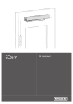
04
Boiler
05
Reservoir
Vacuum flap
Separator
Vacuum generator
Worm drive
Lambda sensor
Burner
Ignition device
Air mass sensor
Grate cleaning drive
Heat exchanger cleaning
Controller
Using the controller
The controller is equipped with a pressure sensitive "resistive touchscreen". It therefore must be used differently
from a smartphone with capacitive touchscreen, which responds to even a very light touch.
Do not use pointed or sharp objects on the touchscreen.
5.1 Cleaning
The touchscreen may only be cleaned with a soft cloth. To wet the cloth, use a monitor cleaning product (e.g.
antistatic foam cleaner), water with detergent or alcohol. In order to prevent humidity from entering the device,
spray the cleaning product onto the cloth and not directly onto the screen itself. Do not use abrasive products,
chemicals, scouring agents or hard objects, as they can scratch and damage the screen.
8
5.2 Overview of controls and indicators
1
Date
Press to change/set the date
2 Time
Press to change/set the time
3 Outdoor temperature
-10° C, if no exterior temperature sensor is connected
4 Chimney sweep function
Only to be activated by authorised personnel
5 Settings/technician level
Opens the system page – the icon is displayed highlighted in
white.
6 Overview page
Opens the overview page – the icon is displayed highlighted in
white. Press again to switch between the overview page and the
homepage
7 Main controller switch
1
Current message
2 Navigation path
Displays information, warnings and faults which have not been acknowledged. Pressing the
message opens the acknowledge dialogue.
Indicates which page is currently being displayed.
5.2.1. Basic controls
Close
i
Closes the current selection/indicator window
If a window is open with the "close" button in the top right hand corner (e.g. the numerical keyboard) - the contorls
outside the window are disabled including the main on/off function.
Back
Returns to the previous page
Scroll up
Displays values higher up a list.
Scroll down
Displays values further down a list.
Temperature setting: Right arrow = increase - left arrow = decrease
9
5.2.1.1 Numerical keypad
1
Left arrow
Decrease value by one unit
2
Minus
Assigns a negative sign to an existing (entered) value.
3
Point
Decimal point for non-integer numbers
4
Maximum value
Indicates the upper limit for an entry
5
Right arrow
Increase value by one unit
6
Minimum value
Indicates the lower limit for an entry
7
Cancel
Cancels the current value / deletes the most recently entered digit.
8
Accept
Accepts the entry and closes the keypad
5.2.2. System ON/OFF
Red: The system is OFF.
Green: The system is
ON.
Yellow: Either the boiler or
the heating circuit are on, but
not both.
Press the main switch button to open the ON/OFF dialogue.
1
Separate main switch
2 ON/OFF
10
Pressing this switch turns the boiler and heating circuit ON/OFF independently.
Press to turn the system ON/OFF
5.2.3. Time settings
Grey: Opens the time settings page (on the component detail pages)
Red: The time settings page is open
Up to three time windows can be set for each day of the week (Mon–Sun), in which the corresponding component
is activated
In order to apply a given setting to multiple days, mark the days in question (left) by touching/swiping them (e.g. MonFri with white background) BEFORE making the settings themselves. All settings made thereafter will apply to all the
marked days.
Active:
Inactive:
1
Time window status (active/inactive)
Press to turn the time window ON/OFF
2
Start time
3
End time
i
The start time must precede the end time. For 24-hour ("round the clock") operation, set the start time to
00:00 and the end time to 23:59.
11
12
Boiler
Buffer
Heating circuit
Overview
Start page
Hot water
Solar
Storage
5.3 Menu structure
5.3.1. User level
5.3.1.1. Start page
1
Eco
Shows the combustion efficiency. It is normal for the indicator to move in the left (grey) zone during
ignition, and does not indicate a defect.
2
Power
Shows the boiler power (percent of nominal power)
3
Pellet
Shows the day container filling level (left = empty, right = full)
5.3.1.2. Overview page
Up to six components with their status and principal parameters are displayed on the overview page.
Pressing a component field opens the respective detailed page, where settings can also be made.
1
Navigation arrows
Used to switch between overview pages when more than six components are
present
2
Component
3
Status display
The status of each component is displayed at the top right.
4
Component designation
The name is used to identify the component, especially when the system has
multiple components of the same type (e.g. heating circuit). The name can be
modified in module configuration (see component designation, page 27)
13
Status display
The following symbols apply to multiple component types. Component-specific symbols are detailed below for
each component separately.
None
Symbol
OFF
The entire system/boiler/power distribution or component is switched off.
Ready
The component is in standby. When all start conditions are satisfied, it goes into active
mode.
Active
See description of component (below)
Warning
The component cannot operate properly. Messages (see page 21) are accompanied by
a corresponding entry.
Frost
protection
Components
Boiler with current boiler
temperature
Fill day container, prepare for ignition, ignition,
STL process
Burn, heat, burn out, post-ventilate
Buffer with upper and
lower temperature
i
Buffer charging in progress
Even though buffer loading is shown to be active, the charging pump is not necessarily running.
The buffer charging pump is only activated when the boiler temperature is at least 3° C greater than
the upper buffer temperature. When the boiler temperature is less than 1° C greater than the upper
buffer temperature, the charging pump is switched off.
Hot water with current
temperature
Hot water charging active (see buffer information above)
Heating circuit with current
flow temperature
Day operation (within the set time window) The flow
calculation is done in relation to the "Day temperature"
setting
Lowering mode (outside the set time window). The
flow calculation is done in relation to the "Reduced
temperature" setting
Summer mode. The heating circuit is switched off (pump
off, mixer closed)
Solar with current collector
temperature
14
Solar charging active (pump running)
5.3.1.3 Boiler
1
2
3
4
5
Current status / phase of boiler
Remaining duration of current phase (e.g. burning)
Next phase of boiler
Phase after next phase of boiler
Cause of termination of most recent heating phase, with time of occurrence
5.3.1.4 Buffer
Charging starts when the time is within an active time window and the upper buffer temperature is below the "Switch
on temperature" setting. If the lower buffer temperature rises to above the "Switch off temperature" setting, charging
stops.
If the time window expires during a charge cycle, the cycle is continued until the deactivation temperature is reached.
1 Current upper buffer temperature
(activation criterion)
2 Mode
3
Off
The buffer is never charged (exception: see frost protection page 36)
On
Charging is controlled as described above
Automatic
Like On with summer mode:
When all users connected to the buffer are Off or in summer mode
(in case of heating circuits), the buffer itself is switched off until heat is
required once more.
If no users are assigned, it behaves as in On mode.
Current lower buffer temperature
(deactivation criterion)
15
5.3.1.5 Hot water
Charging starts when the time is within an active time window and the hot water tank temperature is below the
"Switch on temperature" setting. If the temperature rises to above the "Switch off temperature" setting, charging stops.
If the time window expires during a charge cycle, the cycle is continued until the deactivation temperature is reached.
1 Current hot water temperature
(activation/deactivation criterion)
2 Mode
3
Off
The hot water is never heated (exception: see frost protection page 36)
On
Charging is controlled as described above
Circulation time
like hot water
The same time settings apply as for hot water
own
Specific circulation pump time settings can be applied (clock field
displays)
4
Current circulation temperature
acts as activation/deactivation criterion (only displays when a
temperature sensor is connected)
i
The circulation settings are only displayed when this option is enabled in module configuration.
Circulation
Without a temperature sensor, the circulation pump runs continuously during the activated time windows (according
either to the hot water time settings or to its own circulation time settings). If a temperature sensor is present, the
circulation pump runs during the activated time windows when the measured temperature is below the activation
temperature setting. If the circulation temperature remains equal to / higher than the activation temperature for at
least one minute, the pump stops running once more.
16
5.3.1.6 Heating circuit
The heating circuit is controlled by the ambient temperature, i.e. the flow temperature is determined in relation to the
outdoor temperature. Up to three time phases can be set per day, in which the target temperature is given by the "Day
temperature" (in the living space). Outside these phases, the lower "Reduced temperature" takes effect.
Once the outdoor temperature exceeds the summer temperature (see summer temperature, page 25) for the duration
of the switching delay (see switching delay, page 25), the heating circuit switches to summer mode. Switching to
heating (Day/Lowering) happens in a similar way when the temperature drops below the winter temperature (see
winter temperature, page 25).
A special summer deactivation occurs when the calculated target flow temperature lies below the minimum flow
temperature setting.
Basic settings
Mode
Heating circuit operating mode
Day temperature
Off
Pump off, mixer closed.
Automatic
The flow temperature is calculated from the characteristic curve and the
day/lowering time settings are observed. Switching between summer/
winter modes is active.
Day
The flow temperature is calculated from the day temperature characteristic
curve. Lowering is deactivated. Switching between summer/winter modes
is active.
Set back
temperature
The flow temperature is calculated from the lowering temperature
characteristic curve. Switching between summer/winter modes is active.
Room
thermostat
The mode (day/lowering/auto) can be set on the room controller. If no
room controller is connected, the heating circuit runs in auto mode.
Fix
The flow temperature is regulated to the fixed temperature setting (see
fixed flow temperature, page 25). The time settings have no effect.
Switching between summer/winter modes is not active.
The target room temperature during the heating phases enabled with the time settings.
In order for this temperature to actually be achieved in the room, the flow temperature
characteristic curve must be set properly in relation to the building and the heating system
(floor heating, wall-mounted radiators, etc.)
Reduced temperature The target room temperature outside the heating phases enabled with the time settings.
i
To make the heating circuit switch off during the lowering phase, the lowering temperature
must be set so low that the flow temperature characteristic curve gives a target flow
temperature below the minimum flow temperature.
17
Flow temperature characteristic curve
The flow characteristic determines the relationship between the flow temperature and the outdoor temperature.
1 Up arrow
Increases the flow target temperature, left -20° C, right +20° C outdoor
temperature
2 red value (left)
Day flow target temperature at -20° C outdoor temperature
3 blue value (left)
Lowering flow target temperature at -20° C outdoor temperature
The difference between the day and lowering flow target temperatures is given by the
difference between the day and lowering temperatures (see basic settings, page 17)
multiplied by the "room influence"
4 Down arrow
Decreases the flow target temperature
5 dashed line (top)
Maximum flow temperature
6 red value (right)
Day flow target temperature at +20° C outdoor temperature
7 blue value (right)
Lowering flow target temperature at +20° C outdoor temperature
8 dashed line (bottom)
Minimum flow temperature
18
5.3.1.7 Solar
The solar pump runs when the collector exceeds the minimum temperature and is hotter than the tank. The controller
can switch between two tanks.
1
Mode
Off
The solar pump never runs
Automatic
Solar heating system running
2
Target temperature buffer 1
If the tank 1 temperature (e.g. hot water tank) lies below this value, the
valve switches to tank 1. The temperature of tank 1 is combined with
that of the collector as an activation/deactivation criterion for the solar
pump.
3
Current buffer 1 temperature
4
Maximum temperature buffer 1
If the tank 1 temperature is higher than this value, the valve switches to
tank 2 (e.g. buffer storage tank). The temperature of tank 2 acts as an
activation/deactivation criterion for the solar pump.
5.3.1.8 Storage
The specified consumption is only a guide, and is not intended to be the only criterion for ordering pellets. The
storage filling level must be necessarily checked at regular intervals.
Once the storage has been refilled, the calculated consumption can be reset to 0.0 tons.
Time settings
In order to assure efficient operation, the filling of the day container should interrupt the heating cycle as little as
possible, and occurs at the following conditions:
Boiler start during an active time window and filling level under 90 %, or
end of an active time window and filling level under 70 %.
Basically, the container should only be filled during an active time window. In order to assure hot water supply even
at periods of peak demand or during a too short time window, the container is filled when the filling level lies below
minimum level, even outside an active time window.
Filling can be started independently of the time settings on the maintenance page (see page 21).
If the automatic heat exchanger cleaning cycle is required (depending on the duration of heating), it runs at the same
time as the daily bin is being filled.
19
Messages
Maintenance
System info
20
Hours of operation
Boiler log
System page
Energy log
Components
Settings
5.3.2 Technical level
5.3.2.1 Messages
There are two types of messages:
Warnings/information, which allow the system to be operated further, and faults, which switch off the boiler. In order
to start the boiler again, the fault must be eliminated and reset.
1
red text
Unacknowledged fault
2 white text
Unacknowledged warning/information
3 grey text
Acknowledged message (information/warning/fault)
4 Message number
Values of 1000 or higher are information/warning messages. If the message number is
below 1000, it is a fault.
5 Date & time
Time of occurrence
Pressing the message opens the acknowledge dialogue.
5.3.2.2 Maintenance
Ash emptied
Resets the ash filling level after the ash container has been emptied out.
Start filling
Starts the daily bin filling cycle.
Start component test
Runs the automatic unit test
5.3.2.3 System info
Displays important boiler information, including the type designation, serial number and various version numbers.
5.3.2.4 Hours of operation
1
Performance
Lists the hours of operation in the various power ranges and the grand total (at the bottom).
2
Components
Displays the hours of operation of each unit including the number of starts (right).
21
5.3.2.5 Boiler log
The controller saves the most important heating system operating values every day. In order to analyse this data /
optimise operation of the system, these records can be displayed on the controller.
1
More…
Calls up the controls for configuring the display
Opens the value selection page
Displays the records for the current day
Selects older records (ordered by month)
Displays the reason for termination of the heating cycle in text
2
left
Shifts the displayed time period back in time (only when zoomed in)
3
greater/smaller Changes the displayed time period (max. 00:00-24:00). This can also be done by pressing
the area of the display you wish to display in greater detail.
4
right
Shifts the displayed time period forwards in time (only when zoomed in)
5
Keys
The names of the selected values in their assigned colours
6
Reason for
termination
When this option is enabled (see 1), the reason why and when heating was switched off is
displayed.
7
Time axis
No more than a single day can be displayed
8
Designation
Contains the date and time of occurrence of the displayed record
Format: …_YYYYMMDD_HHMMSS
Select data
Up to six parameters can be displayed at a time. If you press a selected (coloured) text, the value is removed from
the curve – its name is shown in white. When six values have already been selected and you wish to display another,
you must first deselect one value in this way.
22
5.3.2.6 Energy log
See Boiler log, page 22
Shows the heat distribution records.
5.3.2.7 Components
When the boiler is running, you can select components (boiler, buffer, heating circuit, etc.) to display the status of
their units and the values of the corresponding sensors.
If the boiler is off and in standby (heating operation must have shut down in an orderly manner), all outputs can
be turned on/off
i
If a unit is to be automatically turned on/off while its page is open, its status does not change. Only when
you quit the unit page does the change take effect. This can happen for example with the buffer charging
pump in after-run mode.
The active/on status of an input is indicated with a yellow circle
Inactive/off with a grey circle.
5.3.2.8 Settings
If multiple versions of a given type of component are present (e.g. heating circuits), their names and are shown at the
top right, with arrows for selecting them.
23
Boiler
> Settings > Boiler
1
Minimal demand
temperature
This sets the lower limit value for the target temperature.
2
Start difference to target
temperature
If the boiler temperature drops below the target temperature + this value, the
boiler starts.
E.g.: 70° C target temperature for buffer charging + (- 5° C) offset = boiler
starts at 65° C
3
Max. boiler temperature
The heating phase stops when the boiler temperature exceeds this value.
4
External demand
temperature
If no heating distribution is configured on the controller and the boiler is
controlled by an external controller or is to be kept at a constant temperature,
the desired
target temperature must be set here.
If a buffer, hot water tank or heating circuit are configured, this value must be
set to 0.
0° C
5
Minimal output
Sets the lower limit for the power modulation range.
Essentially, this value may not be set lower than 30 %.
30 %
6
Maximal output
Sets the upper limit for the power modulation range.
100 %
7
Daily bin capacity
This value is essential for calculating the filling level and hence the filling
process (if the fuel's dust content is very high, it may need to be reduced).
1
8
Burner auger extraction
rate
This value is essential for calculating the filling level of the container and
hence the filling process
1
9
Switching function
external input
Adaptation to the switching cycle of an external controller
10
Frost protection
If an outdoor temperature sensor is present and its value is lower than this
setting, the frost protection cycle starts.
If no outdoor temperature sensor is present, the frost protection cycle starts
when the boiler temperature falls below 15° C (not adjustable).
If the temperature rises at least 1° C over the frost protection threshold, the
frost protection cycle is stopped (in both the above cases).
-99° C completely disables the frost protection function.
11
Grate running time
The duration of the burner grate drive's stroke from closed to fully open
1
12
Grate lag time
The period between grate sensor activation and fully closed. The half of this
value is used for the grate movements in heating mode, hence this value may
not exceed the actual run time (from sensor activation to mechanical stop) by
more than 20%
1
13
Ignition lag time
After ignition has been detected, the ignition unit continues running for this
time.
1
14
Max. ignition time
If ignition is not detected in this time, the igniter is switched off and a fault is
reported.
15
Burning time
Duration of period between ignition detection and the heating phase
1
16
Burning out phase
Duration of the shutdown process
1
17
Heat exchanger
cleaning time
Duration of the automatic heat exchanger cleaning cycle
1
18
Maximum heat duration
After this time expires, the cleaning heating phase terminates.
1
19
Integral time output
controller
This setting adapts the boiler power regulation to the response speed of the
users.
0…proportional control: e.g. 50 % boiler power, when the boiler temperature
is 5° C less than the target value
20
Max. flue gas
temperature
The boiler power setting is reduced when the flue gas temperature exceeds
this value.
1
21
Numbers of feeding
systems
Number of suction turbines
1
22
Suction fan type
Affects fan control.
1
23
Primary fan type
Affects fan control.
1
23
Secondary fan type
Affects fan control.
1
1
Depends on the type of boiler
24
60° C
5° C
80° C
Opener
-99° C
10 min
20 min
Feeding system
> Settings > Feeding system
1
Feeding time
Room discharge run time
Total run time of suction turbine = suction process + conveyor run + suction after-run
25 s
2
Drive cycle duration
For intermittent room discharge duration of phase during which "Drive pulse
duration" is activate during discharge.
6s
3
Drive pulse duration
For intermittent room discharge: see "Drive cycle duration"
E.g. the drive pauses for 2 seconds every 8 seconds
-> Drive periodic time = 10 s, pulse drive run time = 8 s
If room discharge is intended to be on for the the entire conveyor run time, "Drive
cycle duration" and "Drive pulse duration" must have the same value (e.g. 6 s).
6s
4
Suction pre-running Time span between flap closing and start of feeding system
time
2s
5
Suction postrunning time
5s
At the end of "Feeding time" (feeding system stops) the suction turbine carries
Heating circuit
> Settings > Heating circuit
1
Mode
See page 17
2
Day temperature
See page 17
22° C
3
Reduced
temperature
See page 17
20° C
4
Flow temperature at Leftmost end of heating circuit characteristic curve (for 21° C room
-20° C
temperature)
60° C
5
Flow temperature at Rightmost end of heating circuit characteristic curve (for 21° C room
+20° C
temperature)
28° C
6
Minimum flow
temperature
If the calculated flow target temperature falls below this value, the heating
circuit switches to summer mode.
25° C
7
Maximal
temperature
If the flow temperature rises above this setting, the mixer approaches.
55° C
8
Fixed flow
temperature
If the operating mode is Fixed, the flow is regulated to this temperature.
32° C
9
Summer
temperature
If the outdoor temperature is higher than this value, the heating circuit
switches to summer mode (this value may not be lower than the winter
temperature).
20° C
10
Winter temperature
If the outdoor temperature is lower than this value, the heating circuit
terminates the summer mode (this value may not be higher than the summer
temperature).
18° C
11
Switching delay
This is the time for which the outdoor temperature must be higher than the
summer temperature/lower than the winter temperature, before the mode
switches.
30 min
12
Room influence
The ratio between room and flow temperature (important e.g. when
changing the day temperature and operation with the room controller).
E.g. In order to increase the room temperature by 1° C, the flow temperature
must be increased by 2° C.
2.0
13
Room stat influence
active
When a room controller is connected and this value is set to ON, the flow
target temperature is corrected by the difference between the actual room
temperature and the target temperature.
Off
14
Mixing valve running In order for the mixer controller to operate correctly, the mixer run time
time
must be set here (usually specified on the mixer drive).
15
Proportional factor
Mixer controller parameter
10,000
16
Integral time
Mixer controller parameter
0 ms
17
Derivative time
Mixer controller parameter
0 ms
18
Sample rate
Mixer controller parameter
30 s
140 s
25
Buffer
> Settings > Buffer
1
Mode
See page 15
2
Switch on temperature
See page 15
55 °C
3
Switch off temperature
See page 15
55 °C
4
Superelevation
Charging process: Boiler target temperature = buffer deactivation
temperature + overshoot
Changing the overshoot affects the duration of buffer charging.
5 °C
5
Maximum lag time
In order to exploit the residual energy in the boiler, the storage tank
pump runs after charging has finished fro at most the after-run time,
so long as the boiler temperature is higher than the upper buffer
temperature (hysteresis: On +3 / Off +1 °C). During the after-run time,
the pump may be turned on again, even if the boiler is switched off.
30
min
6
Number of integrated
hot water tank
Important for combined tanks (see page 28)
0
Hot water
> Settings > Hot water
1
Mode
See page 16
2
Switch on temperature
See page 16
45 °C
3
Switch off temperature See page 16
55 °C
4
Superelevation
If the hot water tank is subordinated to the boiler, then during charging:
Boiler target temperature = hot water tank switch off temperature +
superelevation
Changing the superelevation affects the duration of hot water tank
charging.
10 °C
5
Maximum lag time
If the hot water tank is attached to the boiler, the description of the
buffer applies.
If the hot water tank is connected to buffer, then this parameter must be
set to 0.
30 min
Solar
> Settings > Solar
1
Mode
See page 19
2
Target temperature
buffer 1
See page 19
45 °C
3
Maximum temperature
buffer 1
See page 19
55 °C
4
Collector minimum
temperature
The collector must reach at least this temperature before the solar
pump runs.
40 °C
5
Hysteresis pump on
The solar pump can only be activated when the collector temperature
is greater than the tank temperature by at least this amount.
10 °C
6
Hysteresis pump off
The solar pump is switched off when the collector temperature and
tank temperature fall below this value.
5 °C
7
Collector sensor type
Changes to the sensor type setting only take effect when the controller
is rebooted (shut off power for at least 5 seconds).
26
Pt1000
Module configuration
> Settings > Module configuration
Overview
Represents all components of the system with their designations in hierarchical order. Subordinate components are
thus set back (e.g. the "1st Floor" heating circuit is attached to the buffer). The component designation can be edited
by pressing on the list entry itself. The service technician can also edit the hydraulic assignment (to the boiler or
buffer) on this page.
The three buttons (top) are used for switching between pages.
Configuration
This page is protected by the Service Code password.
Press on a numerical field to enter the desired amount. "Internal" and "External" refer to the type of expansion module
– built into the boiler or installed outside the boiler in a separate housing.
Press the "Accept" button to accept the changes (the controller must be switched off).
i
If a solar component is added or removed, the controller must be rebooted after the change has been
confirmed (shut off power for at least 5 seconds). The reason for this is the switch type of the collector
temperature input.
i
If a hot water and circulation component are internally configured, the hot water component is NOT
associated with the HZS532. Hot water and circulation are then on an HZS533. The index depends on
the other components and is shown on the Modules page.
Maximum component numbers
Buffer
5
Hot water tank
3
Circulation
3
Heating circuit
10
Solar
3
Feeding system
2
27
Combined tank
If a combination tank is present, both a buffer and a hot water tank must be configured.
The charging pump is connected to the buffer pump output, while the hot water temperature sensor is connected to
the hot water temperature input.
The "Number of integrated hot water tank" must be set (normally 1) in the buffer settings.
If buffer mode is "Automatic", the buffer will no longer be fully charged during the summer (all connected heating
circuits off or in summer mode). Hot water is still generated using the hot water temperature sensor and buffer
charging pump.
Modules
Lists all necessary (expansion) modules with their assigned functions.
1
2
Green square Communications with module OK
Grey square Module not detected/communications not OK
Assignment of the modules in the following sequence:
1. Buffer
The first internal buffer is assigne always on the main mother board 524, additional buffers on intern expansion
module 533.
2. Hot water tank
The first intern assigned hot water tank is always on the intern expansion module 532, except if in connection with a
circulation (in this case the intern expansion module 533 is needed).
3. Heating circuit
The first intern asssigned heating circuit is always on the intern expansion module 532, additional ones on intern
expansion module 533
4. Feeding
One intern assigned feeding system is always on the intern expansion module 532
Two feeding systems can be connected to the extern expansion module 541
5. Solar
If both internal and external expansion modules are used, assign first the internal modules
I.e. Assign 6 internal modules and 4 external heating circuits as follows:
Heating circuit 1: Internal expansion module 532
Heating circuit 2–6: Internal expansion module 533 No. 1–5
Heating circuit 7–10: External expansion module 541 No. 1–4
i
28
Move additional components (i.e. Hotwater tank) under the module assignement of existing elements
(i.e. heating circuits). When using an external expansion module, change only the Dip switch so that
no changes on the wiring is necessary.
Serial number
Enter the 14-digit serial number (5-digit prefix, 2-digit language ID and 7-digit boiler number) and confirm with the
"Accept" button.
2.4 Remote access
> Settings > Network
The ReFlex controller can be operated directly with a PC/laptop (with Ethernet connection), or remotely via a LAN
or the internet (with a router). The user interface is identical with that on the boiler itself.
The network cable must be connected to the "X4 Ethernet" socket on the back of the touchscreen controller. In
order to integrate the heating system controller into the network, a free "IP-Address" must be assigned to it. Enter
the values of the network in the "Network mask". The "Gateway" is the IP address of the router.
i
Changes to the network settings only take effect after the page has been closed (e.g. with the Back
button) and the controller itself is rebooted (shut off power for at least 5 seconds).
If you wish to be able to connect to the controller from outside the LAN (i.e. via internet), you must establish a
connection to a router capable of forwarding multiple ports to the controller (so-called "port forwarding", see
below).
If the router does not have a fixed IP address (dependent on the internet access/provider), it must be assigned a
DNS name with a DNS service.
Depending on the device used to access it, you can choose between "WEB Server" and "VNC Server".
2.4.1 Web server
Remote control with the Java applet only requires a Java-enabled browser. Normally, PCs or laptops are already
equipped to do so with no additional programs.
Enter the controller's IP address (direct Ethernet connection) or router's IP address or DNS name in the browser's
address bar to call up the "LRS Application Online Settings" page. Select "Fast Transmission" and click on <Ok>; you
are then prompted to enter the password ("LRS Operating System Login" – confirm again with <Ok>).
If the controller page does not display after a few seconds, you have entered the password incorrectly.
Available ports: 80, 1954, 1983
2.4.2 VNC server
In this mode, a VNC Viewer/Client is required on the remote station. Since this is a standard process, such programs
are available even for smartphones and tablets.
Available ports: 1954, 5900
2.4.3 Email
Messages (information, warning, fault) can be sent to up to three recipients by email. The following settings are
required:
- Data of the outgoing email account
If a DNS name is given for the SMTP server, a "DNS-Server" must be specified on the "Network" page.
- Up to three recipient-email addresses, which can be set to "only errors" or "all messages".
The email's subject line will contain the text "Pellets-Heizung" (Pellet heating system) followed by the boiler serial
number
29
06
Annex
A. Module assignment
Maximum
number
Internal
External
Main board 524
1
Internal expansion module 532
1
Internal expansion module 533
5
External expansion module 541
16
PIN CONFIGURATION
230 V AC 3-pole
Temperature sensor 2-pole
L
Input
N
GND
GND
Temperature sensor 3-pole
Input
230 V AC mixer 4-pole
L (mixer open/circulation pump)
free
L (mixer close)
GND
Remote room sensor connection “RTF H11”
(from 2013)
N
GND
3
2
1
Plug
Expansion
module
(internal)
Buffer on motherboard 524
1
2
30
X18
X17
Remote
room sensor
Buffer tank temperature top
Buffer tank temperature bottom
3
X6
Buffer pump
Internal expansion module 532
1
2
3
4
X8
X4
X3
X5
Heating circuit mixer
5 X9
Heating circuit pump
6 X10
Feeding system
7 X11
Hot water pump
Hot water temperature
Flow temperature
Room thermostat
Internal expansion module 533
Heating circuit
1 X6 Heating circuit pump
2 X3 Heating circuit mixer
Solar
3 X8 Flow temperature
4 X11 Room thermostat
1 X6 Solar pump
2 X3 Switching valve
Hot water with circulation
3 X7 Collector temperature (Pt 1000)
4 X8 Buffer 1 temperature
5 X11 Buffer 2 temperature
1 X6 Hot water pump
2 X3 Circulation pump
3 X7 Hot water temperature
4 X8 Circulation temperature
31
External expansion module 541
The CAN-bus wiring should be run using shielded twisted-pair cables (Cat5 or 6 shielded). Please ensure that the
shield of the cable is properly earthed to minimise interface along the cable.
Dip switch:
Dip switch
External modules are numbered in progressively increasing order during configuration (1-16). The dip switches must
be set accordingly.
0 - invalid
(Delivery condition)
230 V AC 3-pole
X1 Power supply
X2 Power to next module,
X4, X6
1
2
CAN Bus
X14 Input
X15 Output (if not used:
150Ω termination resistor)
GND
CAN B (High)
N
CAN A (Low)
L
230 V AC mixer 4-pole
X12 Remote room sensor
“RTF H11” 3-pole (optional)
X5
3
2
1
GND
N
L (mixer close)
L (mixer open/
circulation pump)
3
X12 Circulation
temperature
GND
free
Input
ExpansionRemote
module
room sensor
(external)
Heating circuit
1 X4 Heating circuit pump
2 X5 Heating circuit mixer
32
3 X12 Room thermostat
4 X9 Flow temperature
Feeding system
1
2
X4
X6
Feeding system 1
Feeding system 2
Buffer & hot water & circulation
1X4
Buffer pump4
X12
Circulation temperature
2
X5
Circulation pump
5 X10
Hot water temperature
3
X6
Hot water pump
6
X8
Upper buffer temperature
7
X9
Lower buffer temperature
Solar
1X4
Buffer pump3
X10
Collector temperature
2
X5
Switching valve4
X8
Buffer 1 - temperature
5
X9
Buffer 2 - temperature
33
Main board 524
X26 Burner feeder relay
X21 Lambda sensor
X23 0...10V
X27 Burner feeder
overtemperature
X25 Secondary air mass
X24 Primary air mass
X36 Suction fan RPM
X15 Flue gas temperature
X28 Grate limit switch
X18 Upper buffer temperature
X32 Shutter sensor
X14 Boiler temperature 2/
lower
X30 External contact
X17 Lower buffer temperature
X35 Pellet storage –
Full level sensor
X13 Boiler temperature
X16 Outdoor temperature
X37
Connection
to actuator
X38 Bus
connection
to internal
extension
X1
Power supply
X11
Power supply
for internal
extension
X12 STL
X5 Ignition
X9 Burner feeder
worm
X6 Return/
buffer pump
X8 Suction fan
PZ65/100: Primary fan
34
X3 Grate drive
X4 Suction
turbine
X7 Fault output
X2 Heat exchanger
cleaning
Fuses
Designation
Rating [A]
F1
0.25
Description
Transformer main board
F2
5
Suction fan (X8), burner feeder worm (X9)
F3
10
Ignition (X5)
F4
10
Suction turbine (X4)
F5
10
Heat exchanger cleaning (X2), grate unit (X3)
F6
10
Return pump (X6)
F7
2.5
Lambda sensor heating
F8
2.5
24V power unit
Pin configuration
230 V AC 3-pole
X1, X2, X4, X5, X6, X8, X9, X10
Temperature sensor/analogue input 2-pole
X13 – X18, X23
L
Input
N
GND
GND
Lambda sensor 4-pole
X21
230 V AC 4-pole
X3 Grate drive
Input positive
L (Grate close)
Wire Nr. 2
Input negative
L (Grate open)
Wire Nr. 3
Sensor heating
N
Wire Nr. 1
Sensor heating
GND
No-voltage 3-pole
X7 Fault output
Analogue output 3-pole
X26
24 V
normally closed
Analogue output
Root
Analogue GND
normally open
230VAC 4-pole
X11 Power supply for internal extension modules
L
L switched via STL – not used
N
GND
230 V AC 2-pole
X12 STL
L
L switched
Burner feeder overtemperature/external contact
X27, X30
24 V
Input
Digital input 3-pole
X28, X32, X35, X36
24Vbrown
Inputblack
GNDblue
CAN Bus 4-pole
X38
24 V
CAN A
CAN B
GND
35
B. Frost protection
Each component has its own frost protection process.
Buffer
If the buffer is off (power manager Off or mode Off), charging is started when indicated by the
activation/deactivation temperature, regardless of the time settings.
Hot water
If the hot water tank is off (power manager Off or mode Off), charging is started when indicated by
the activation/deactivation temperature, regardless of the time settings.
Heating
circuit
If the heating circuit is off (power manager Off or mode Off), the heating circuit is run in reduced
mode.
C. Seizing protection
If the pumps have not been run for a week, they are turned on for a minute. The mixer drives are opened and closed
again for double the mixer run time (before the heating circuit pump is turned on).
07
Regular maintenance
In order to keep the system in good working efficiency and order, the boiler must be cleaned at regular intervals.
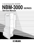
7.1 Empty out the ash compartment / clean the combustion chamber
Depending on the quality of the pellets, the ash compartment and combustion chamber must be emptied out and
cleaned every 6 – 18 weeks. These are located behind the left housing hatch and are closed with the ash compartment /
combustion chamber doors (secured with a spoked handle / wingnut respectively).
• Procedure
CAUTION: Never attempt to handle hot ash or glowing embers!
Press the ON/OFF switch to turn the
heating off.
CAUTION:
We recommend leaving the system 2 - 3 hours to cool down after switching it off
Please note that damage caused by failure to observe the maintenance
instructions is not covered by the warranty/guarantee.
36
• Open the lower cleaning hatch.
• Extract the ash container and empty it out.
• Open the upper cleaning hatch and place the ash container beneath it.
• Remove any fly ash which has accumulated on the combustion chamber bulkhead (a scraper for this purpose can
be obtained from Biotech or your dealer).
• Use a vacuum cleaner to remove any residual ash so that the combustion chamber is completely clean.
• Use a suitable vacuum cleaner to clean any residual ash out of
the ash compartment as well.
• Place the ash container back in its compartment.
• Close the cleaning hatches.
• Press the "Empty ash" button in the "Maintenance" menu
to confirm that the system has been cleaned.
• The removed ash can be used as compost or
disposed of with biological waste.
• Start the system up again.
This job can also be done by our customer service technician
during the yearly overhaul!
37
08
38
Notes
Natural, sustainable
heating
with Biotech pellet and chipping heating systems.
Biotech Energietechnik GmbH
Mayrwiesstraße 12
5300 Hallwang, Austria
T +43 662 454072-0
F +43 662 454072-555
[email protected]
www.biotech-heizung.com