1
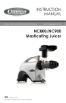
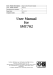
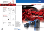
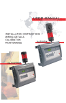
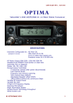
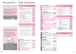
15385 CARRIE DRIVE
GRASS VALLEY, CA 95949
PHONE: (530) 477-8400
TECH. LINE: (530) 477-8402
FAX: (530) 477-8403
SALES: (800) 874-8663
e-mail: [email protected]
web:www.norcommcorp.com
MODEL NC804 VOICE
ENCRYPTION SCRAMBLER
INSTRUCTION MANUAL
INTRODUCTION
The Model NC804 is a micro-miniature voice-plus pseudo-random rolling code scrambler designed to provide high level security for two-way radio voice
communication systems. It’s unique digital encryption processing algorithm, plus it’s many features makes the Model NC804 a perfect cost effective
solution for high-end voice encryption scrambling for commercial users, police departments, public safety organizations and other systems as a defense
against unauthorized interception of private and sensitive voice transmissions by casual or even the most determined listeners.
The Model NC804 features 8 user key codes with over 20 trillion codes to choose from. Single line or double tap mode for selection of scramble or clear
function, audible (speaker beeps) or LED (visual) outputs of mode selection and start to speak sequence, over the air kill disable for stolen or lost radios,
six programmable operating features, and 4 layer SMT assembly.
Measuring 0.90" W x 1.30" L x 0.22" H, the Model NC804 supports limited space applications and is plug compatible in most applications with our popular
Model NC802 voice inversion scrambler making it ideal for system upgrades.
OPERATION
The Model NC804 scrambles speech by transposing the inband voice spectrum into alternative frequencies. This is accomplished by a proprietary
digital encryption algorithm that pseudo randomly changes the rolling code sequence frequency generator an average of 1000 times per second with
an average dwell time of ±1.1 milliseconds. The NC804 is continuously churning it’s data comprised of the selected key code, while waiting for either
the reception of transmitted packet data or activation of the PTT function. It is important to know that cipher keys are never transmitted, but rather the
unit’s address and sync cue. When scramble mode is enabled and the unit transmits it’s packet data, all units within the system compare the data to
their own coded address. If the address is the same deciphered reception is automatic. Clear reception is also automatic.
Security of system depends on the secrecy of users code keys. To maintain secure operation it is recommended that key codes be changed from time
®
to time. Reprogramming of key codes and other features requires the use of the inexpensive Model NC800 P.C. Programming Adapter and Windows
based software package.
NOTE: Export of the Model NC804 is controlled by the U.S. Department of State, Office of Defense Trade Control. License to export this product is
required by the United States Department of Commerce. It is the users responsibility to comply with all government regulations regarding
the
use of this product.
SPECIFICATIONS
FORMAT .................................................. Rolling code encryption.
SECURITY LEVEL................................... High level.
CODE KEY MEMORIES .......................... 3 line binary selection of 8 key codes.
KEY CODES ............................................ 6 Digit address (over 20 Trillion code combinations). Six (6) Digit Key Coded Address can be made up from
any of the printable characters on the P.C. keyboard. Note: Lower case alpha keys are automatically default to
upper case characters.
KILL FUNCTION ...................................... To disable radio if stolen or lost.
ENCRYPTION ALGORITHM ................... Real time/frequency domain.
SYNCHRONIZATION .............................. Allows late entry reception.
PACKET DELAY ...................................... Programmable 100ms to 850ms.
PACKET INTERVAL ................................ 960ms
NC804 REV. E
04/04
1
PACKET DURATION ............................... 60ms.
DWELL TIME ........................................... ±1.1ms average.
BANDWIDTH ........................................... 300Hz to 2800Hz.
AUDIO INPUT LEVEL ............................. Adjustable from 3.5 to 710mV-rms @ >50K ohms, D.C. blocked.
AUDIO OUTPUT LEVEL ......................... Adjustable from 3.5 to 710mV-rms @ <2K ohms, D.C. blocked.
INPUT/OUTPUT GAIN ............................. Typically less than ±1dB.
MEMORY ................................................. Non-volatile EEPROM.
CIPHERED RECEPTION ........................ Automatically detects scrambled mode.
SCRAMBLE INDICATORS...................... [1] Sink or Source LED driver.
[2] Audible (Beeps) speaker driver.
SCRAMBLE/CLEAR ENABLE ................ [1] Single line (active high or low).
[2] Double tap of momentary switch.
PTT INPUT ............................................... Active 'low' to transmit.
FOR TECHNICAL SUPPORT
CALL 530-477-8402
OPERATING VOLTAGE .......................... 5.5VDC to 20VDC.
OPERATING CURRENT ......................... Less than 10mA .
o
OPERATING TEMPERATURE ............... -30 C to +70oC.
SIZE .......................................................... 0.90"W x 1.30"L x 0.22"H
22.85mm x 33.02mm x 5.6mm
MOUNTING .............................................. Double sided adhesive tape.
INTERFACING ......................................... Micro-miniature header and 12 inch Teflon color coded cable assembly.
®
SYSTEM PROGRAMMING ..................... Model NC800 Windows based Programming software, and RS-232 P.C. adapter.
SPECIFICATIONS ARE SUBJECT TO CHANGE IN THE INTEREST OF TECHNICAL
IMPROVEMENT WITHOUT NOTICE OR OBLIGATION
PROGRAMMING
All Programming with the exception of input and output level settings are performed using the inexpensive Model NC800 P.C. Programming Adapter
®
and Windows based software. Unless otherwise specified the Model NC804 scrambler functional parameters and key codes come factory defaulted
for conventional operation as noted in the instruction manual. Reprogramming the NC804 is accomplished using the Model NC800 Programmer via
®
direct connection to a standard P.C. serial port and loading the Windows 95/98/NT compatible software, then simply following the on-screen menu to
select user desired operating parameters and key codes. The NC800 software is a very intuitive and easy to use program with context sensitive help
pertaining to every aspect of programming just a mouse click away!
Once the Model NC804 scrambler module has been programmed it can then be used while still connected to host P.C. and transceiver as a “RF” modem
to perform “Over The Air Kill Function” (OTAK) to disable radio if stolen or lost (only available in version 1.24 and higher).
PACKET SYNCHRONIZATION DELAY
In scramble mode, the NC804 transmits a 60mS synchronization data burst at the beginning of each transmission and is repeated every one (1)
second. This data provides no key code information, but is required for proper operation and support of late entry reception. Depending on the type
of radio system, a data synchronization delay may be required. This is due to the response time between activation of transmit PTT and speaker audio
at receiving point. Care must be used in determining this delay as time will vary from system to system. For dependable cipher operation, the NC804
must wait for this time period prior to sending packet data sequence.
As an example, units talking through a repeater system may require 250 to 350mS delay. This is typically 100mS for transmit PTT circuitry and 150 to
250mS for repeater CTCSS detect. The NC804 is default programmed for 150mS delay and is adequate for direct operation (no repeater). The delay
time can be user programmed from 150mS to 850mS in 100mS increments using the Model NC800 P.C. Programmer. For some users it may be
difficult to determine when to start to speak due to packet delay and can result in loss of the first part of voice message. To accommodate this condition,
the NC804 can be programmed to provide an audible beep indicating “Start To Speak”.
NC804 REV. E
04/04
2
INTERFACING
As supplied, the Model NC804 is fully adaptable for most applications. It is, however, recommended that before final installation and for optimum
performance that installation be performed by a qualified technician using the correct test equipment and that both transmit and receive audio input
levels to the NC804 be measured independently and, if necessary, that the correct gain setting resistors be installed. Refer to MIC and RX input
interfacing procedures to determine input signal levels and selection of appropriate resistor values. The use of a service monitor with audio generator
and an oscilloscope or A.C. rms voltmeter is required for these measurements. A piece of double sided adhesive tape is provided to eliminate the need
for mounting hardware. When scrambler is ready for installation, remove protective covering from one side of tape and attach to the bottom side of P.C.
board. Now remove protective cover from remaining side of tape and adhere scrambler to desired location, making sure that mounting surface is clean
and dry to insure positive mounting. If possible, scrambler should be located away from intense r.f. fields and all leads be kept to minimum lengths, with
unused leads removed from cable assembly. NOTE: Refer to Figure 5 page 6 for typical circuit configuration before installation.
RED (2)..................................................... Connect to a +5.5 to 16VDC regulated D.C. source. Because both receiver and microphone low level audio
[+ SUPPLY]
passes through the NC804, it is very important to use a quiet and stable D.C. voltage to reduce the possibility
of introducing power supply noise that would alter these audio signals.
BLACK (10).............................................. Connect to common TX and RX ground location. Power supply noise and ground loops may result in TX or
[- SUPPLY] ............................................... RX audio stages if ground return is not common to both.
YELLOW (11) ........................................... [METHOD 1] Connect this lead in series with a SPST switch to ground or to radio's software switch providing
[SCRAMBLE/CLEAR SELECT] ............... a logic 'LOW' (to ground) when programmed to enable scramble mode on a per-channel selection.
DEFAULT=METHOD 1 ............................
YELLOW (11) ........................................... [METHOD 2] Connect this lead to the radio's Monitor switch providing a momentary closure to ground when
[SCRAMBLE/CLEAR SELECT]
pushed. Reconfigure in software for DOUBLE TAP MODE. This feature eliminates the need for a software or
DOUBLE TAP MODE= METHOD 2
SPST switch sometimes not available in today's portable radios. Using this feature allows the user to toggle
between scramble and clear modes by simply pushing the radio's monitor switch TWO times in rapid
succession (Double tapping). The NC804 generates a 900 Hertz tone output to the radio speaker responding
with TWO beeps to indicate selection of scramble mode and ONE long beep for clear mode.
WHITE/GREEN (5)................................... [METHOD 1] This output is current limited by a 1K ohm resistor and will source 2.5 volts at 3mA when in the
[VISUAL INDICATOR] = METHOD 1
scrambled mode. Connect this lead to the ANODE of a high efficiency 'LED' and the CATHODE of the 'LED to
ground. NOTE: For sinking (to ground), reconfigure in software for sinking. Many radios have spare indicators
such as Busy, Monitor, Call Aux, Back lighting, etc. that can be used for this option.
[Refer to Figure 5 page 7 for typical circuit configuration].
WHITE/GREEN (5)
[RX AUDIO ENABLE]= METHOD 2
[METHOD 2] When configured via the NC800 programmed, this output works in conjunction with the audio
beep output „GREEN‟ lead to enable the receivers audio output amplifier during the DOUBLE TAP or BEGIN TO
SPEAK BEEP tone generation. This output can be configured to sink or source external circuitry. Refer to radio’s
service manual to determine sink or source compatibility to enable muted receiver’s audio amplifier circuitry.
GREEN (14) ............................................. Connect this lead directly to the high side of portable radio speaker or to input of receiver's audio amplifier
[AUDIBLE BEEP OUTPUT] ..................... through a series resistor. The value of this resistor will have to be selected for desired audio output level.
This feature is used for “Double Tap” and Begin To Speak Beep Mode. NOTE: If connected to receiver’s
audio output amplifier, refer to RX AMP ENABLE [METHOD 2].
BROWN (13) ............................................ Connect this lead to transmit PTT circuitry that goes 'low' (to ground) during transmit mode.
[PTT INPUT] .............................................
GRAY (8) .................................................. These inputs provide binary selection of one of eight key codes. If all inputs are left unconnected
BINARY CODE SELECT [B1]
(ungrounded), key code one is defaulted. Selection of the seven alternate key codes is accomplished with the
WHITE (9)
radio code selection or by use of a binary coded switch connected to the gray, white and violet leads of
BINARY CODE SELECT [B2]
cable assembly. [Refer to Figure 1 page 5 for Key Code selection].
VIOLET (7)
BINARY CODE SELECT [B4]
BLUE (6) .................................................. Connect these two leads directly in series with the output of the receiver's discriminator circuitry for optimum
[RX AUDIO INPUT] .................................. recovered audio. In some cases, the removal of a resistor or coupling capacitor makes for an ideal circuit
& .................................................... break point. To insure receiver audio quality, perform input level measurements and make sure that break
ORANGE (3) ............................................ point connections are NOT made between the discriminator and CTCSS or SQUELCH circuitry or any other
[RX AUDIO OUTPUT] .............................. type of decoder, if installed, and in a location so not to interrupt an internal D.C. bias voltage in the
receiver's audio stages. NOTE: Because of filtering circuitry, both CTCSS and carrier SQUELCH signals
will not pass through scrambler. DTMF and other in-band decoders may fail to function because of signal
inversion and level changes. If it is necessary to connect to audio path after CTCSS decoder, make sure to
bypass or disable the CTCSS High Pass Filter if used. The NC804 contains a high pass filter to filter out
CTCSS tones. [Refer to Figure 5 page 6 for typical circuit configuration].
NC804 REV. E
04/04
3
RX LEVEL TEST PROCEDURES:
To determine receiver input level, select clear mode and connect an oscilloscope or A.C. rms voltmeter to the solder junction of [RX AUDIO INPUT]
BLUE LEAD (6) and circuit break point in discriminator. Using a service monitor, generate a full quieting signal modulated with a 1KHz tone at full
system deviation then measure signal level. Use this measurement to select from "RX GAIN CHART" the appropriate resistor values for R1 and R6
[Refer to Figure 3 page 5 for location of R1 and R6]. NOTE: Verify that the [RX AUDIO OUTPUT] ORANGE LEAD (3) has near the same level
measured at input.
RX GAIN LEVEL CHART
INPUT
mV-P-P
INPUT
mV-RMS
OUT
R1
IN
R6
10-50
3.5-18
10K
10K
50-150
18-53
15K
15K
150-500
53-175
33K
33K
500-1000
175-350
82K
82K
1000-2000
350-710
200K
200K
200K
200K
FACTORY SELECTED
BLUE/WHITE (12).................................... Connect these two leads directly in series with the transmitter's microphone and modulator circuitry.
[MIC AUDIO INPUT]
Determine, first, if the microphone is D.C. biased by measuring for a voltage potential across the microphone
&
element. If the microphone is D.C. biased , the leads must be connected between the bias circuitry and
BLACK/WHITE (1)
FIRST microphone amplifier stage as the NC804 will not pass bias voltage. In some cases the removal of a
[MIC AUDIO OUTPUT]
resistor or coupling capacitor makes for an ideal circuit break point. To insure transmit audio quality, perform
input level measurements and make sure that break point connections are made BEFORE the transmitter's
PRE-EMPHASIS or LIMITER circuitry and in a location so as to NOT interrupt any internal D.C. bias voltage
in the modulator audio stages. [Refer to Figure 5 page 6 for typical circuit configuration].
MIC LEVEL TEST PROCEDURES:
To determine microphone input level, select clear mode and connect an oscilloscope or A.C. rms voltmeter to the solder junction of [MIC AUDIO
INPUT] BLUE/WHITE INPUT LEAD (12) and circuit break point in modulator. Key transmitter and speak loudly into microphone or with an acoustically
coupled 1KHz audio tone not exceeding 2/3 system deviation, then measure the signal level. Use this measurement to select from the "MIC GAIN
LEVEL CHART" the appropriate resistor values for R2 and R5 [Refer to Figure 3 page 5 for location of R2 and R5]. NOTE: Verify that the [MIC
AUDIO OUTPUT] BLACK/WHITE LEAD (1) has near the same level measured at input.
MIC GAIN LEVEL CHART
INPUT
mV-P-P
INPUT
mV-RMS
OUT
R2
IN
R5
10-50
3.5-18
10K
10K
50-150
18-53
15K
15K
150-500
53-175
33K
33K
500-1000
175-350
82K
82K
1000-2000
350-710
200K
200K
15K
15K
FACTORY SELECTED
NC804 REV. E
04/04
4
FIGURE 1
KEY CODE SELECTION CHART
1 = LEAD NOT GROUNDED
0 = LEAD GROUNDED
KEY
B1
B2
B4
DEFAULT KEY
CODES
1
1
1
1
111111
2
0
1
1
222222
3
1
0
1
333333
4
0
0
1
444444
5
1
1
0
555555
6
0
1
0
666666
7
1
0
0
777777
8
0
0
0
888888
PCB TOP VIEW
FIGURE 2
PCB BOTTOM VIEW
FIGURE 3
NC804 REV. E
04/04
5
FUNCTIONAL BLOCK DIAGRAM
NC804 REV. E
04/04
6
TYPICAL CIRCUIT CONFIGURATION
NC804 REV. E
04/04
7
WARRANTY POLICY
NorComm products are unconditionally guaranteed for two (2) years on materials and labor from date of purchase.
All Warranty repairs must be performed at NorComm's Customer Service Department in Grass Valley, CA. Units under warranty can be returned for
repair or replacement without prior authorization, however, a letter explaining the defect should be enclosed with the unit. Out of warranty units returned
constitute Purchaser's authorization for NorComm to repair or replace equipment and to invoice Purchaser for any and all reasonable costs of repair
labor, parts and freight.
NorComm shall not be obligated to repair or replace equipment rendered defective, in whole or in part, by causes external to the equipment, such as,
but not limited to, catastrophe, power failure, or transients, environmental extremes, improper use, and maintenance or interfacing applications.
NorComm further assumes no liability for any incidental or consequential damages which may result from the applications of its products by the
Purchaser or any other party.
NC804 REV. E
04/04
8