1
Document ID: 1550920
2005 Pontiac GTO
Page 1 of 9
| GTO (VIN V) Service Manual | Engine | Engine Controls - 6.0L | Description and Operation |
Document ID: 1550920
Fuel System Description
System Overview
The fuel tank stores the fuel supply. An electric fuel pump, located in the fuel tank with the fuel
sender assembly, pumps the fuel to the fuel rail assembly. The pump provides the fuel at a
pressure greater than is needed by the injectors. The fuel pressure regulator, part of the fuel
sender assembly, keeps the fuel available to the injectors at a regulated pressure. The fuel system
is returnless.
Fuel Tank
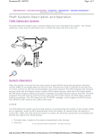
The 70-litre (18.5 gallons) fuel tank is a pressed steel construction. A two piece high density
polyethylene shell (1, 3) encapsulates the fuel tank (2). The fuel tank is fitted immediately behind
the rear seat and is accessed through the trunk. The fuel tank is held in place by two mounting
straps and the fuel filler neck is attached to the vehicle body at the fuel filler opening, located in
the rear right-hand quarter panel, with three fastening nuts. The fuel tank itself is not repairable
and if damaged must be replaced.
Fuel Tank Filler Pipe
The fuel tank filler pipe has a built-in restrictor and deflector in order to prevent refueling with
leaded fuel.
Fuel Filler Cap
© 2012 General Motors Corporation. All rights reserved.
http://localhost:9001/si/showDoc.do?docSyskey=1550920&pubCellSyskey=63992&pubO... 2/25/2012
Document ID: 1550920
Page 2 of 9
Notice: If a fuel tank filler cap requires replacement, use only a fuel tank filler cap with the same
features. Failure to use the correct fuel tank filler cap can result in a serious malfunction of the fuel
and EVAP system.
The fuel filler cap (3) is a screw-on type, with an integrated tightening torque limiting mechanism.
When installing the cap, tighten it until a ratcheting (clicking) sound is heard, indicating the cap is
properly tightened. The fuel tank filler cap is tethered to the fuel filler pocket. The fuel tank filler
cap requires a quarter of a turn in order to be removed.
Fuel Sender Assembly
http://localhost:9001/si/showDoc.do?docSyskey=1550920&pubCellSyskey=63992&pubO... 2/25/2012
Document ID: 1550920
Page 3 of 9
An in-tank modular fuel pump and sender assembly is attached from the top of the fuel tank and
incorporates a modular fuel pump assembly, a fuel strainer and fuel filter, a reservoir, fuel level
sender assembly, pressure regulator and reservoir jet pump. A fuel fill limiter vent valve (FLVV)
and fuel tank pressure sensor is incorporated into the modular fuel pump and sender cover
assembly.
Fuel Pump
The fuel pump is incorporated into the design of the modular fuel sender assembly inside the fuel
tank and is an electric, high pressure, single turbine design. The fuel pump provides fuel to the fuel
rail assembly at a specified flow and pressure. The fuel pump delivers a constant flow of fuel to the
engine, even during low fuel conditions or aggressive vehicle manoeuvres. The engine control
module (ECM) controls the electric fuel pump operation through the fuel pump relay.
Fuel Pressure Regulator Assembly
The fuel pressure regulator is a diaphragm-operated relief valve located in the modular fuel pump
and sender assembly. Its principal function is to maintain a controlled pressure at the injectors at
all times by regulating fuel flow into the fuel feed line. The injector pulse width varies with the
signal from the manifold absolute pressure (MAP) sensor. With the ignition ON and the engine OFF,
system fuel pressure at the pressure test connection should be 380-440 kPa (55-64 psi). If the
pressure is too low, poor performance could result. If the pressure is too high, excessive odor and
a Diagnostic Trouble Code (DTC) may result. Refer to Fuel System Diagnosis for information on
diagnosing fuel pressure conditions.
Fuel Pump Strainer
The fuel strainer connects onto the fuel pump inlet port on the end cap of the fuel pump assembly
and consists of a finely woven plastic filter. A metal compression ring is fitted around the plastic
strainer to fuel pump feed port and the complete fuel strainer assembly is fastened to the fuel
pump end cap with a metal speed clip fastener. The strainers function is to filter fuel contaminants
from within the fuel reservoir and also act to wick the fuel. The fuel strainer is serviced as part of
the complete fuel pump and strainer assembly. Fuel stoppage at the strainer indicates an abnormal
amount of sediment in the fuel tank which should be removed before reinstallation of the fuel tank
into the vehicle.
Fuel Filter Assembly
The fuel filter assembly is contained within the modular fuel pump and sender assembly reservoir
and forms the containment housing for the fuel pump. The filter comprises a paper element which
traps particles in the fuel that may damage the fuel injection system. The fuel filter is made to
withstand maximum fuel system pressure, changes in temperature and exposure to fuel additives.
Fuel Level Sender Assembly
The fuel level sender assembly comprises of a fuel level float and wire arm assembly, a ceramic
variable resistor card assembly , and a detachable nylon wiper. The ceramic resistor card is
attached to a plastic card holder which attaches to the reservoir. A metal contact fork with brushes
is connected to the detachable nylon wiper. This assembly provides a variable circuit resistance to
the engine control module (ECM) depending on wiper contact position. Two circuit wires run from
the resistor card and extend up to connect with the modular fuel pump to cover assembly wiring
connector on the underside of the modular fuel pump and sender assembly cover. The ECM
http://localhost:9001/si/showDoc.do?docSyskey=1550920&pubCellSyskey=63992&pubO... 2/25/2012
Document ID: 1550920
Page 4 of 9
averages out any slosh variation in the fuel tank and sends this signal to the fuel level indicator on
the instrument panel fuel gauge.
Nylon Fuel Pipes
Caution: In order to Reduce the Risk of Fire and Personal Injury:
• If nylon fuel pipes are nicked, scratched or damaged during installation, Do Not attempt to
repair the sections of the nylon fuel pipes. Replace them.
• When installing new fuel pipes, Do Not hammer directly on the fuel harness body clips as it
may damage the nylon pipes resulting in a possible fuel leak.
• Always cover nylon vapor pipes with a wet towel before using a torch near them. Also, never
expose the vehicle to temperatures higher than 115°C (239°F) for more than one hour, or
more than 90°C (194°F) for any extended period.
• Before connecting fuel pipe fittings, always apply a few drops of clean engine oil to the male
pipe ends. This will ensure proper reconnection and prevent a possible fuel leak. (During
normal operation, the O-rings located in the female connector will swell and may prevent
proper reconnection if not lubricated.)
Nylon fuel pipes are designed to perform the same job as the steel or flexible fuel pipes or hoses
that they replace. Nylon pipes are constructed to withstand maximum fuel system pressure,
exposure to fuel additives, and changes in temperature. There are 3 sizes of nylon pipes used:
3/8 in ID for the fuel feed, 5/16 in ID for the fuel return, and 1/2 in ID for the vent. Heat-resistant
rubber hose and/or corrugated plastic conduit protect the sections of the pipes that are exposed to
chafing, to high temperature, or to vibration.
Nylon fuel pipes are somewhat flexible and can be formed around gradual turns under the vehicle.
However, if nylon fuel pipes are forced into sharp bends, the pipes will kink and restrict the fuel
flow. Once exposed to fuel, nylon pipes may become stiffer and are more likely to kink if the pipes
are bent too far. Take special care when working on a vehicle with nylon fuel pipes.
Quick-Connect Fittings
Quick-connect fittings provide a simplified means of installing and connecting fuel system
components. The fittings consist of a unique female connector and a compatible male pipe end. Orings, located inside the female connector, provide the fuel seal. Integral locking tabs or fingers
hold the fittings together.
Fuel Pipe O-Rings
O-rings seal the threaded connections in the fuel system. The fuel system O-ring seals are made of
a special material. Service the O-ring seals with the correct service part.
EVAP Pipes and Hoses
The evaporative emission (EVAP) pipes extend from the fuel sender assembly and the EVAP
canister vent solenoid to the EVAP canister. These pipes are located on top of the fuel tank. The
EVAP purge pipe extends from the EVAP canister on top of the fuel tank to the EVAP purge solenoid
in the engine compartment. The rear pipes and the engine compartment pipe are constructed of
nylon. The chassis EVAP purge pipe is constructed of steel. The EVAP canister vent solenoid
connects to the EVAP canister with a section of rubber hose.
http://localhost:9001/si/showDoc.do?docSyskey=1550920&pubCellSyskey=63992&pubO... 2/25/2012
Document ID: 1550920
Page 5 of 9
Enhanced Evaporative Emission (EVAP) Service Port
The enhanced evaporative emission (EVAP) service port is located in the EVAP pipe in the engine
compartment near the purge solenoid. The service port is identified by a green cap. The port
contains a schrader valve and a fitting in order to allow the connection of the J 41413-200
Evaporative Emissions System Tester (EEST) for diagnosis of the evaporative emission system.
On-Board Refueling Vapor Recovery System (ORVR)
The on-board refueling vapor recovery system (ORVR) is an on-board vehicle system that is
designed to recover the fuel vapors during the vehicle refueling operation. The flow of liquid fuel
down the fuel filler pipe provides a liquid seal, which prevents the vapor from leaving the fuel filler
pipe. An evaporative emission (EVAP) pipe transports the fuel vapor to the EVAP canister for use by
the engine. Listed below are the ORVR system components with a brief description of their
operation:
• The EVAP canister. The EVAP canister receives refueling vapor from the fuel system, stores
the vapor and releases the vapor to the engine upon demand.
• The EVAP pipes. The EVAP pipes transport the fuel vapor from the fuel tank to the EVAP
canister.
• The fuel filler pipe. The fuel filler pipe carries the fuel from the fuel nozzle to the fuel tank.
• The check valve. The check valve limits fuel spit back from the fuel tank during the refueling
operation by allowing the fuel flow only into the fuel tank. This check valve is located at the
bottom of the fuel filler pipe.
• The modular fuel sender assembly. The assembly pumps the fuel to the engine from the fuel
tank.
• The fill limiter vent valve (FLVV). This valve acts as a shut-off valve. The FLVV is located at
the top of the fuel sender assembly. This valve is not serviced separately. The FLVV has the
following functions:
http://localhost:9001/si/showDoc.do?docSyskey=1550920&pubCellSyskey=63992&pubO... 2/25/2012
Document ID: 1550920
Page 6 of 9
- The FLW controls the fuel tank fill level by closing the primary vent from the fuel tank.
- The FLW prevents the fuel from exiting the fuel tank via the EVAP pipe to the canister.
- The FLW provides fuel-spillage protection in the event of a vehicle rollover by closing the
vapor path from the tank to the EVAP canister.
Modes of Operation
The engine control module (ECM) looks at voltages from several sensors to determine how much
fuel to give the engine. The fuel is delivered under one of several conditions called modes. The ECM
controls all modes.
Starting Mode
With the ignition ON, before engaging the starter, the engine control module (ECM) energizes the
fuel pump relay for two seconds allowing the fuel pump to build up pressure. The ECM first checks
speed density, then switches to the mass air flow (MAF) sensor. The ECM also uses the engine
coolant temperature (ECT), throttle position (TP), and manifold absolute pressure (MAP) sensors to
determine the proper air/fuel ratio for starting. This ranges from 1.5:1 at -36°C (-33°F) to 14.7:1
at +94°C (+201°F) running temperature. The ECM controls the amount of fuel delivered in the
starting mode by changing the pulse width of the injectors. This is done by pulsing the injectors for
very short times.
Clear Flood Mode
If the engine floods, clear the engine by pushing the accelerator pedal down all the way. The
engine control module (ECM) then pulses the injectors at an air/fuel ratio of 20:1. The ECM holds
this injector rate as long as the throttle stays wide open and the engine speed is below 300 RPM. If
the throttle position becomes less than 80 percent, the ECM returns to the starting mode.
Run Mode
The run mode has two conditions called Open Loop and Closed Loop. When the engine is first
started, and engine speed is above a predetermined RPM, the system begins Open Loop operation.
The engine control module (ECM) ignores the signal from the heated oxygen sensor (HO2S) and
calculates the air/fuel ratio based on inputs from the engine coolant temperature (ECT), mass air
flow (MAF), manifold absolute pressure (MAP), and throttle position (TP) sensors. The system stays
in Open Loop until meeting the following conditions:
• Both HO2S have varying voltage output, showing that they are hot enough to operate
properly. This depends on temperature.
• The ECT sensor is above a specified temperature.
• A specific amount of time has elapsed after starting the engine.
Specific values for the above conditions exist for each different engine, and are stored in the
electrically erasable programmable read only memory (EEPROM). The system begins Closed Loop
operation after reaching these values. In Closed Loop, the ECM calculates the air/fuel ratio (injector
on-time) based on the signal from various sensors, but mainly the HO2S. This allows the air/fuel
ratio to stay very close to 14.7:1.
Acceleration Mode
http://localhost:9001/si/showDoc.do?docSyskey=1550920&pubCellSyskey=63992&pubO... 2/25/2012
Document ID: 1550920
Page 7 of 9
When the driver pushes on the accelerator pedal, air flow into the cylinders increases rapidly, while
fuel flow tends to lag behind. To prevent possible hesitation, the engine control module (ECM)
increases the pulse width to the injectors to provide extra fuel during acceleration. The ECM
determines the amount of fuel required based on throttle position, coolant temperature, manifold
air pressure, mass air flow and engine speed.
Deceleration Mode
When the driver releases the accelerator pedal, air flow into the engine is reduced. The engine
control module (ECM) looks at the corresponding changes in throttle position, manifold air pressure
and mass air flow. The ECM shuts OFF fuel completely if the deceleration is very rapid, or for long
periods, such as long closed throttle coast-down. The fuel shuts OFF in order to protect the warmup three-way catalytic converters.
Battery Voltage Correction Mode
When battery voltage is low, the engine control module (ECM) compensates for the weak spark
delivered by the ignition system in the following ways:
• Increasing the amount of fuel delivered
• Increasing the idle RPM
• Increasing ignition dwell time
Fuel Cutoff Mode
The engine control module (ECM) cuts OFF fuel from the fuel injectors when the following
conditions are met in order to protect the powertrain from damage and improve driveability:
• The ignition is OFF. This prevents engine run-on.
• The ignition is ON, but there is no ignition reference signal. This prevents flooding or
backfiring.
• The engine speed is too high, above the red line.
• The vehicle speed is too high, above rated tire speed.
• During an extended, high speed, closed throttle coast down, this reduces emissions and
increases engine braking.
• During extended deceleration, in order to prevent damage to the catalytic converters.
Fuel Trim
The engine control module (ECM) controls the air/fuel metering system in order to provide the best
possible combination of driveability, fuel economy, and emission control. The ECM monitors the
heated oxygen sensor (HO2S) signal voltage while in Closed Loop and regulates the fuel delivery
by adjusting the pulse width of the fuel injectors based on this signal. The ideal fuel trim values are
around 0 percent for both short term and long term fuel trim. A positive fuel trim value indicates
the ECM is adding fuel in order to compensate for a lean condition by increasing the pulse width. A
negative fuel trim value indicates that the ECM is reducing the amount of fuel in order to
compensate for a rich condition by decreasing the pulse width. A change made to the fuel delivery
changes the short term and long term fuel trim values. The short term fuel trim values change
rapidly in response to the HO2S signal voltage. These changes fine tune the engine fueling. The
http://localhost:9001/si/showDoc.do?docSyskey=1550920&pubCellSyskey=63992&pubO... 2/25/2012
Document ID: 1550920
Page 8 of 9
long term fuel trim makes coarse adjustments to the fueling in order to re-center and restore
control to short term fuel trim. A scan tool can be used to monitor the short term and long term
fuel trim values. The long term fuel trim diagnostic is based on an average of several of the long
term speed load learn cells. The ECM selects the cells based on the engine speed and engine load.
If the ECM detects an excessive lean or rich condition, the ECM will set a fuel trim DTC.
System Overview
The fuel tank stores the fuel supply. An electric fuel pump, located in the fuel tank with the fuel
sender assembly, pumps the fuel through an in-line fuel filter to the fuel rail assembly. The pump
provides fuel at a pressure greater than what is needed by the injectors. The fuel pressure
regulator, part of the fuel sender assembly, keeps the fuel available to the injectors at a regulated
pressure.
Fuel Pump Electrical Circuit
When the ignition switch is in the ON position, before engaging the starter, the engine control
module (ECM) energizes the fuel pump relay for 2 seconds, causing the fuel pump to pressurize the
fuel system. If the ECM does not receive ignition reference pulses with the engine cranking or
running within 2 seconds, the ECM shuts OFF the fuel pump relay, causing the fuel pump to stop.
Fuel Rail Assembly
The fuel rail assembly attaches to the engine intake manifold. The fuel rail assembly performs the
following functions:
• Positions the injectors (3) in the intake manifold
• Distributes fuel evenly to the injectors (2)
• Fuel Raid Feed Pipe (1)
http://localhost:9001/si/showDoc.do?docSyskey=1550920&pubCellSyskey=63992&pubO... 2/25/2012
Document ID: 1550920
Page 9 of 9
Fuel Injectors
The top-feed fuel injector assembly is a solenoid-operated device, controlled by the engine control
module (ECM), that meters pressurized fuel to a single engine cylinder. The ECM energizes the
injector solenoid, which opens a ball valve, allowing the fuel to flow past the ball valve, and
through a recessed flow director plate. The director plate has multiple machined holes that control
the fuel flow, generating a conical spray pattern of finely atomized fuel at the injector tip. Fuel is
directed at the intake valve, causing the fuel to become further atomized and vaporized before
entering the combustion chamber. An injector that is stuck partly open can cause a loss of pressure
after the engine shutdown. Consequently, long cranking times would be noticed on some engines.
http://localhost:9001/si/showDoc.do?docSyskey=1550920&pubCellSyskey=63992&pubO... 2/25/2012