1
Lotus Service Notes
Section LK
FUEL SYSTEM
SECTION LK - ELISE for North America
Sub-Section Page
General Description
LK.1
3
Fuel Filling
LK.2
4
Precautions
LK.3
5
Fuel Tank
LK.4
6
Fuel Pump/Sender Assembly
LK.5
9
Charcoal Canister
LK.6
10
Fuel Tank Pressure Test
LK.7
11
Page 1
Page 2
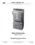
Fuel feed
pipe
Tank breather
connection
Fuel pump
Quick fit
connector
Fuel tank
Pipe to inlet
manifold
Roll over valve
Fuel rail
Fill Level Vent Valve (FLVV)
Fuel filler neck
Vapour Management
Valve (VMV)
em208b
Charcoal canister
Canister vent
close valve
Lotus Service Notes
Section LK
Lotus Service Notes
Section LK
LK.1 - GENERAL DESCRIPTION
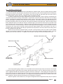
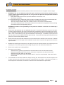
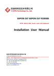
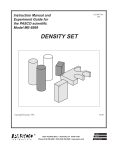
The 10.6 U.S. gall. (40 litre) fuel tank is fabricated from stainless steel, and is mounted within the chassis
crossmember between the passenger compartment and engine bay, and is secured against foam mouldings by
two support brackets from beneath. The fuel filler neck connects with the right hand top of the tank, and an
Onboard Refuelling Vapour Recovery (ORVR) system operates as follows:
In order to ensure that fuel vapour displaced from the tank during the course of filling is cleansed by the
charcoal canister before venting to atmosphere, a liquid seal is used to close off the filler neck from escaping
vapour. The filler tube extends within the tank to within 10mm of the bottom surface, such that the end of the
tube is submerged in liquid fuel under all normal circumstances. A one way valve incorporated at the base of
this fuller tube allows fuel to flow into the tank, but prevents backflow into the filler tube. When the tank is being
filled, displaced vapour from within the tank is vented through a Fill Level Vent Valve (FLVV) mounted in the
top of the tank, to the charcoal canister. Additional venting also takes place via a port in the top plate of the fuel
pump, from where it is routed through a roll-over valve (to prevent fuel spillage in case of vehicle inversion)
mounted on the centre top of the tank, before joining the pipe between FLVV and canister. This vent, in
conjuction with a 3mm orifice in the filler pipe just below the top surface of the tank, allows tank venting when
the car is parked on a side slope.
When the fuel reaches a specified level in the tank, a bouyant ball in the FLVV seals off the breather
aperture and causes a pressure rise in the filler neck to shut off the delivery discharge nozzle. Full tank
capacity has now been achieved. It is NOT recommended to attempt to fill the tank beyond this level.
Canister vent close valve
Air filter
Float level vent valve
Roll over valve
To fuel tank
breather port
Charcoal canister
To engine
intake plenum
Vapour management
valve
pl4405mtc
The fuel pump/fuel gauge sender unit is mounted into the left hand top surface of the tank, and includes
a submerged turbine type pump which draws fuel through a strainer 'sock' for delivery through a non-return
valve, integrated fuel filter and a pressure regulator valve to the outlet port. A fuel supply pipe is clipped to the
pump outlet port and is routed through the rear wall of the fuel tank bay, to feed the fuel rail for the four fuel
injectors at a pressure of around 325 kPa. The single line fuel system eliminates fuel circulation back to the
tank, resulting in reduced fuel tank temperature and evaporative emissions.
When the ignition is first switched on, the engine management ECU energises the fuel pump for a period
Page 3
Lotus Service Notes
Section LK
of about 3 seconds to prime the system before switching off. If a signal from the crankshaft sensor indicates
that the engine is being cranked or is running, the fuel pump feed will be maintained. The pump is switched off
immediately when the ignition is switched off, or about 3 seconds after a stall. Note that if coolant temperature
at the time of ignition switch off is over 88°C, the ECU remains powered for a period of 20 minutes to allow for
heat soak management (see sub-section KH.5). Re-energising the ignition during this period will not run the
fuel pump until the ECU receives a crank signal.
A safety inertia switch is incorporated into the fuel pump electrical circuit, and operates in a severe impact
(indicative of a vehicle collision) to switch off the fuel pump feed and minimise the fire risk. The switch is
located in the engine bay on the inner face of the left hand chassis siderail, and is reset once tripped, by
pressing the rubber button on the top of the switch.
Fuel pump inertia switch
ohs137
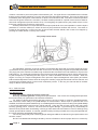
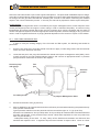
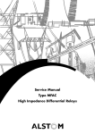
An evaporative emissions 'charcoal' canister is mounted at the right hand front of the engine bay and is
connected to the air space inside the fuel tank via the FLVV and fuel pump top plate as previously described.
The purge port of the canister is routed through a solenoid valve mounted on the inlet manifold, to a port on the
intake plenum. The evaporative emissions control system prevents untreated fuel vapour from the tank reaching the atmosphere, by absorbing the tank vapour in a bed of activated charcoal in the canister. When the
engine is running, the engine management ECU opens the Vapour Management Valve (VMV) and allows
intake manifold depression to draw fresh air through the canister, purging absorbed fuel from the charcoal, and
consuming the resultant vapour in the normal combustion process. In this way, the charcoal bed is 'cleaned'
ready to absorb more tank vapour.
LK.2 - FUEL FILLING
Fuel Requirement
USE UNLEADED PREMIUM GRADE GASOLINE.
Use only unleaded gasoline meeting ASTM specifications. Use of fuels not meeting ASTM specifications could cause poor performance and increase emissions.
For optimum vehicle performance and fuel economy, the use of super or premium unleaded gasoline,
with a minimum octane rating of 91 (RON+MON)/2 is recommended. Where super or premium fuel is not
available, the Elise will operate satisfactorily on unleaded gasoline having a minimum rating of 87 (RON+MON)/
2, but vehicle performance and economy will be reduced. Using fuel with a lower octane rating may cause
knocking (pinking) which, if severe, can cause serious engine damage. Light knocking may occasionally be
heard for short periods when accelerating or driving up hills, and this should cause no concern, although using
a lower gear would be advised. If, however, persistent heavy knocking is heard when using the specified fuel,
the cause should be ascertained without delay.
The use of good quality fuels containing proper detergent additives is advised for good performance and
emission control.
Do NOT use leaded fuel: damage caused by the use of leaded or other improper fuel is not covered by
Page 4
Lotus Service Notes
Section LK
the New Vehicle or Emission Control System Warranty. Leaded fuel will damage the oxygen sensor as well as
contaminating the catalytic converter, the effectiveness of which decreases after as little as one tankful of
leaded fuel.
Gasolines Containing Alcohol - Some gasolines sold at service stations contain alcohol although they may not
be so identified. Use of fuels containing alcohol is not recommended, unless the nature of the blend can be
determined as being satisfactory.
Gasohol - A mixture of 10% ethanol (grain alcohol) and 90% unleaded gasoline may be used in the Lotus Elise.
If driveability problems are experienced as a result of using gasohol, it is recommended that the vehicle is
operated on gasoline.
Methanol - Do not use gasolines containing methanol (wood alcohol). Use of this type of alcohol can result in
vehicle performance deterioration and damage to critical parts in the fuel system. Fuel system damage and
vehicle performance problems, resulting from the use of gasolines containing methanol, may not be covered
by your vehicle warranty.
Fuels Containing MMT - Some North American fuels contain methylcyclopentadienyl manganese tricarbonyl
(MMT), which is an octane enhancing additive. Such fuels may damage the emission control system and are
NOT recommended.
Diesel - The Lotus Elise will not operate on diesel fuel.
Fuel Filling
WARNING: Be aware of the danger of explosion when dealing with petrol and its attendant fumes.
Before stopping at a filling station, switch off mobile phones, ensure that all cigarettes are extinguished and that no naked flames or other potential ignition sources are present. Switch off the
engine before refuelling.
Filler Cap: The fuel filler cap is located in the right hand rear quarter panel, concealed beneath a spring loaded
flap. To remove, pull open the flap and turn the cap anticlockwise. As the cap is turned, any slight pressure
differential between the tank and atmosphere will be released, and a brief hiss may be heard, which is completely normal. Note that the cap is tethered by a short strap to protect against loss.
To refit, place the cap into the filler neck and turn clockwise until the ratchet mechanism clicks several
times. Push the flap closed.
Filling Procedure: Insert the pump nozzle fully into the neck, and fill until the auto-shut off mechanism is
triggered. Do not attempt to ‘brim’ the tank to the top of the filler neck, as expansion of the fuel due to
temperature change (cold underground fuel storage) may cause flooding of the fuel tank breather system
charcoal canister, or spillage of fuel. The useable fuel tank capacity is 10.6 U.S. gall. (40 litres).
LK.3 - PRECAUTIONS
The fuel line between pump and injector rail, and the injector rail itself, contain pressurised fuel both when
the ignition is switched on, and for a period after switching off. This feature aids engine starting by reducing the
time needed to build up operating fuel pressure, and by inhibiting the formation of vapour pockets in the supply
line of a stopped hot engine.
WARNING:
i)
To minimise the risk of fire and personal injury, relieve the fuel system pressure before servicing
any part of the fuel supply circuit. See ‘Fuel Pressure Relief Procedure’ below.
ii) To reduce the possibility of sparks occurring when a fuel line is disconnected, or when fuel
vapour is present, the negative battery cable should be disconnected before work is commenced.
iii) When fuel lines are disconnected, absorb any escaping fuel in an absorbent cloth and dispose of
safely.
Page 5
Lotus Service Notes
Section LK
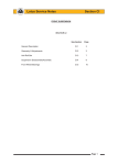
Fuel Pressure Relief Procedure
This procedure should be used prior to disconnecting any part of the fuel line.
-
-
-
-
-
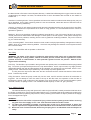
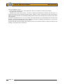
Pull out the fuel pump fuse (on the left
hand side of the engine bay bulkhead,
as shown), start the engine, and run until it stops from starvation. Crank the
engine for a further few seconds.
If the engine is a non-runner, pull out the
fuel pump fuse, and crank the engine for
20 seconds to minimise residual fuel
pressure.
Disconnect the battery.
It is recommended first to release the
quick fit connector located to the rear of
the coolant header tank:
Release the retaining clip securing the
pipe joint to the header tank bracket.
Slide the orange coloured safety lock to
allow access to the connector release
buttons.
Surround the pipe joint with a shop towel
to absorb fuel contained in the pipework
before pressing the release buttons and
separating the joint.
Orange
safety lock
Fuel pump
fuse (20A)
Fuel pipe to
engine
ohs136
WARNING: Be aware of the possibility of full
pressure retention in the fuel line caused
by a system fault.
-
Fuel pipe
from tank
-
-
Before re-making the joint, ensure that the orange safety lock is fitted onto the pipe connector in the orientation shown in the illustration.
Push the male pipe end fully into the female
connector until a click is heard. Pull on the
pipe to ensure complete engagement.
Slide the orange safety lock over the connector to prevent accidental pressing of the release
buttons.
Secure the pipe/connector using the pipe clip
on the header tank bracket.
Release
button
L64
LK.4 - FUEL TANK
The 10.6 U.S. gall. (40 litre) stainless steel fuel tank is mounted within the chassis crossmember between
the passenger compartment and engine bay, and is secured against foam mouldings by two support cradles
from beneath. The fuel filler connects with the right hand top of the tank, and the fuel pump/fuel gauge sender
unit is mounted into the left hand top surface. A removeable panel is provided in the top of the chassis
crossmember in the cabin, and provides access to the fuel pipe connections and harness connector. If the
pump/gauge sender unit is to be replaced, the tank must first be removed from the chassis.
Page 6
Lotus Service Notes
Section LK
To Remove Fuel Tank
If possible, this operation should be performed when the fuel level is low to lighten the tank weight.
1.
WARNING: The fuel line between pump and engine remains pressurised after switching off the
ignition. Before disconnecting the fuel line, carry out the fuel pressure relief procedure detailed
in sub-section LK.3.
Carry out the fuel pressure relief procedure detailed in sub-section LK.3.
Disconnect the battery.
It is recommended first to release the quick fit connector located to the rear of the coolant header tank:
Release the retaining clip securing the pipe joint to the header tank bracket.
Slide the orange coloured safety lock to allow access to the connector release buttons.
Surround the pipe joint with a shop towel to absorb fuel contained in the pipework before pressing
the release buttons and separating the joint.
WARNING: Be aware of the possibility of full pressure retention in the fuel line caused by a
system fault.
2.
Remove the left hand seat and rear bulkhead trim panel. From the left hand rear corner of the cabin,
remove the access panel on the top of the chassis rear crossmember for access to the fuel pump connections. Release the quickfit type connector on the fuel vapour line connection to the pump/sender unit top
plate. Prise out the retaining spring clip and withdraw the fuel feed pipe. Immediately cap all pipes and
ports to protect from dirt ingress and limit vapour hazard. Disconnect the wiring harness plug from the
pump unit, and from the pressure sensor.
3.
Remove the RH rear wheel and wheelarch liner to provide access to the filler hose connection. Release
the filler hose from the tank spigot, and immediately cap the orifice to prevent dirt ingress and reduce the
vapour hazard.
4.
Release the quickfit type connnector on the vapour line to the charcoal canister, and cap the pipe and
canister port. Pull out the grommet surrounding this pipe in the rear wall of the chassis bay.
5.
Remove the engine bay undertray/diffuser.
6.
Disconnect control cables:
Release the two gearchange cables from the transmission levers and abutment bracket.
Release the parking brake cable from the horseshoe compensator and abutment brackets.
Release the throttle cable from the engine.
Release the gearchange cable and throttle cable 'P' clips from the perforated 'shear panel' below
the fuel tank.
7.
From beneath the fuel tank, release the fixings securing the 'shear panel' front and rear edges to the
chassis, and those at each side securing the composite sills to the panel. Note that this panel is a
structural part of the chassis, and that the car should not be used without the panel fitted.
Page 7
Lotus Service Notes
Section LK
8.
Support the tank before removing the two support cradles from the chassis. Each cradle uses two bolts
at the front end of the bracket, and a single bolt at the rear, all threading into Rivnuts in the chassis.
9.
Carefully lower the tank from the chassis, feeding the vapour line through the chassis hole.
10.
Before re-fitting the tank, ensure that all the clamping pads are in place:
- EPDM foam sponge block on upper and lower edges of both tank side faces;
- Expanded Polypropylene saddles on top face of tank;
- Neoprene isolating strip between tank and support cradles;
- EPDM rubber wedge between front bottom edge of tank and support cradles;
- Neoprene sponge foam between upper front of tank and chassis.
Page 8
Lotus Service Notes
Section LK
Polypropylene saddles
Fuel tank
Foam sponge
Rubber wedge
Earth braid
Support
cradle
L59b
11.
Ensure the pump/sender unit, FLVV, roll-over valve and associated pipework is fitted to the tank, with the
earth braid fitted onto the '10 O'clock' position pump mounting stud.
12.
Loose fit the LH tank mounting cradle ensuring that the earth braid is fitted beneath the head of the
horizontally disposed front fixing bolt.
13.
As the tank is raised into position, feed the vent pipe through its hole in the chassis wall. Feed the LH end
of the tank into the cradle, and raise the tank into position taking care not to trap or pinch the fuel pipes or
wiring harness. Retain with the RH cradle, noting that no washer is fitted at the horizontally disposed front
fixing point. Torque tighten the cradle fixing bolts to 24 Nm.
14.
Continue the installation in reverse order to removal, and ensure that the 'shear panel' is fitted beneath
the fuel tank bay before driving the car.
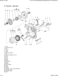
LK.5 - FUEL PUMP/SENDER ASSEMBLY
The combined fuel pump/gauge sender unit is mounted in the left hand end of the tank top surface. A
removeable panel is provided in the top of the chassis crossmember in the cabin, which provides access to the
fuel pipe connections and harness connector, but if the pump/gauge sender unit is to be replaced, the tank
must be removed from the chassis (see sub-section LK.4).
For fuel pump test procedures, refer to Engine Repair Manual B120T0327J.
Page 9
Lotus Service Notes
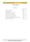
To Remove Pump/sender Assembly
1.
Remove the fuel tank (see sub-section
LK.4).
Section LK
Clamp ring
Spacer ring
2.
Release the eight nuts securing the
clamping ring, and carefully withdraw the
pump assembly from the tank. Immediately
seal the tank aperture to reduce the vapour
hazard and prevent dirt ingress.
Pressure sensor
3.
For permitted disassembly of the pump
unit, refer to Engine Repair Manual
B0120T0327J.
Pump support
4.
To refit the pump assembly, renew the
rectangular section sealing ring before carefully feeding the sender float arm in through
the tank aperture. Orientate the unit with the
breather spigot pointing inboard, and fit the
clamping ring with the location tab engaged
with the recess in the pump top moulding. Fit
and secure the eight M6 washers and nuts.
Pressure regulator
valve
5.
Refit the fuel tank into the car (see subsection LK.4).
Filter & gauge
sender unit
6.
Connect the fuel feed pipe and retain with
the spring clip. Connect the breather pipe to
the spigot on the pump top plate. Fit the harness plugs to the pump/sender connector, and
to the pressure sensor.
Fuel pump
Intake strainer
sock
Cushion
pl4403mt
Retaining cap
LK.6 - CHARCOAL CANISTER
In order to prevent fuel vapour venting from the fuel tank to atmosphere, the breather pipe from the tank
is routed to a canister filled with activated-charcoal, which absorbs and stores the fuel vapour when the engine
is stopped. When the engine is running, the canister is connected to the depression in the inlet manifold via a
port on the intake plenum such that fresh air is drawn through the canister to purge the charcoal of its absorbed
fuel, with the resultant gas then consumed by the engine in the normal combustion process.
Charcoal Canister
This is mounted at the right hand front corner of the engine bay via a bracket fixed to the bulkhead. Fuel
vapour from within the tank and collected from the FLVV and a spigot on the fuel pump/sender top plate, is
routed to the canister port labelled ‘tank’. This port is extended within the canister to the underside of the
charcoal bed, below which is a reservoir to collect any liquid fuel. A second port on the canister ('vent')
connects the top side of the charcoal bed to atmosphere via a solenoid controlled 'close' valve. In this way,
vapour from the fuel tank is cleansed of fuel by the charcoal bed before venting to atmosphere.
The third, 'purge' port, controlled by a solenoid valve mounted on the inlet manifold, connects the underPage 10
Lotus Service Notes
Section LK
side of the charcoal bed with a port on the engine intake plenum. The pulse width modulated vapour management valve is opened during certain engine running conditions in order to allow intake depression to draw fresh
air through the vent pipe and charcoal bed, cleansing the charcoal of fuel before consuming the resultant
vapour in the normal combustion process. In this way, the charcoal is prepared for further vapour absorption.
Control System
The vapour manageement valve is controlled by the engine management ECU, which keeps the valve
closed (unenergised) when the engine is cold or idling in order to maintain idle quality. At normal running
temperatures and engine speeds above idle, the ECU monitors other running conditions and the status of
various management systems, and when appropriate conditions pertain, the ECU will apply a duty cycle to the
valve in order to regulate the amount of purging allowed dependent on the amount of vapour in the canister.
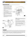
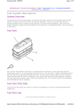
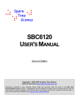
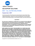
LK.7 - FUEL TANK PRESSURE TEST
In order to verify the sealing integrity of the fuel tank and filler system, the following test should be
performed:
1.
Use the Lotus Scan tool to close the canister vent valve or apply 12 volts and ground to the two terminals
of the vent valve electrical connector.
2.
Locate the test port in the purge line between the canister and vapour management valve (VMV), which
is itself mounted on an inlet manifold plenum bracket, and connect an appropriate tester or pressure
pump and water manometer as shown in the diagram.
Pressure pump
with gauge
Test
port
Charcoal
canister
To intake plenum
L65
Vapour Management Valve
3.
Pressurise the tank to 20"H2O (5.0 kPa).
4.
Allow to stabilise for 30 to 60 seconds then take a reference point and start measuring the pressure decay
over a period of 60 seconds.
Typical pressure reduction over this period should not exceed the region of 1" H2O (0.25 kPa).
Pressure loss of between 2" H2O (0.5 kPa) and 3" H2O (0.75 kPa) will cause the MIL to be illuminated and
a trouble code (P0456 - minor pressure loss) to be set. Minor leaks equivalent to a 0.5 mm (0.020 inch)
hole, may be caused by:
- Inadequate sealing of the VMV. To verify, clamp off the flexible hose between the VMV and inlet
manifold and repeat the test. A significant improvement indicates a suspect valve. Clean or renew.
Page 11
Lotus Service Notes
Section LK
Other possibilities include:
- Poorly sealing fuel filler cap. Check tightness, body foul conditions, sealing ring integrity.
- Pipe and hose connections.
- Canister close vent valve (CCVV). Check by clamping hose between canister and vent valve. A
significant improvement indicates a suspect valve. Clean or renew. Note that once the CCVV and the
VMV have been clamped, any remaining leakage will be either in the canister tank connection or the fuel
tank assembly.
Pressure loss greater than 3" H2O (0.75 kPa) will cause the MIL to be illuminated and a trouble code
(P0442 - major pressure loss) to be set. Causes of this level of leakage, equivalent to a 1.0 mm hole
(0.040 inch) may be caused by any of the above.
A gross leak will cause a trouble code P0455 to be set, the possible causes of which include filler cap
sealing, or fuel filler hose connections.
Page 12