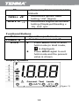
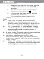
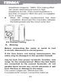
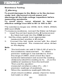
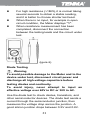
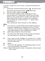
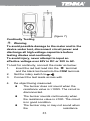
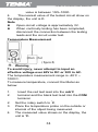
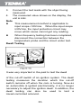
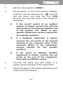
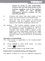
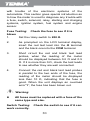
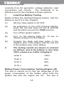
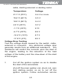
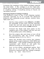
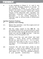
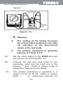
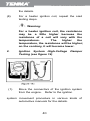
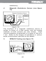
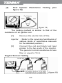
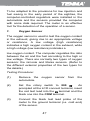
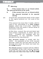
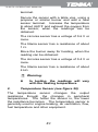
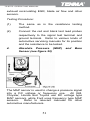
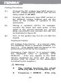
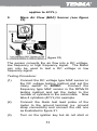
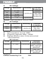
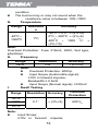
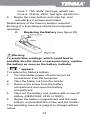
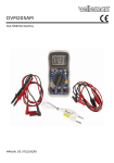
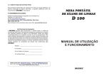
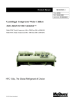
1
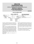
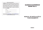
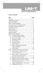
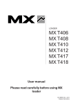
72-9275 Automotive Multi-Purpose Meter P/N:41404552 72-9275: OPERATING MANUAL Contents Overview ................................................................4 Unpacking Inspection .............................................4 Safety Information ..................................................5 Guidelines for Safe Operation ....................5 Automotive Servicing Safety Guide ............8 International Electrical Symbols .............................12 The Meter Structure ...............................................13 Rotary Switch..............................................13 DC voltage measurement ...........................13 AC voltage measurement ...........................13 Resistance measurement ..........................13 Functional Buttons ......................................14 Display Symbols .........................................14 Measurement Operation.........................................15 DC Voltage Testing.....................................15 AC Voltage Testing.....................................17 DC Current Testing.....................................18 1 72-9275: OPERATING MANUAL Resistance Testing ......................................20 Diode Testing...............................................21 Continuity Testing ........................................23 Temperature Measurement .........................24 Frequency Measurement.............................25 Dwell Testing ...............................................26 Operation of Hold Mode...............................29 Automotive Troubleshooting and Diagnosis............29 Fuse Testing: Check the fuse to see if it is blown ...........................................................30 Switch Testing: Check the switch to see if it can work correctly........................................30 Solenoid or Relay Testing............................31 Starting/Charging System Testing ...............31 Battery Power Consumption Testing (Engine off).................................................................32 Trigger Voltage Battery Load Testing ...........34 Voltage Drop Testing ....................................35 Charging System Voltage Testing ................37 2 72-9275: OPERATING MANUAL Ignition System Testing .................................38 Engine Sensor Testing ..................................46 General Specifications ..............................................54 Accuracy Specifications ............................................55 Maintenance..............................................................59 3 72-9275: OPERATING MANUAL Overview This Operating Manual covers information on safety and cautions. Please read the relevant information carefully and observe all the Warnings and Notes strictly. Warning To avoid electric shock or personal injury, carefully read the “Safety Information” and “Guidlines for Safe Operation” before using the meter. The Tenma Automotive Digital Multimeter Model 72-9275 is a 1999 count, 3-1/2 digit manual ranging meter. This meter features a unique design with an extra large LCD display, test leads status display, full overload protection and many other practical features to achieve outstanding performance for safer operation than other meters. In addition to the Dwell, Tach and Data Hold feature, the meter can be used to test the AC voltage, DC voltage, DC current, resistance, temperature, frequency, diodes and continuity. Unpacking Inspection Open the package case and remove the meter. Check the following items carefully for any missing or damaged part: Item Description Qty 1 Operating Manual 4 1 piece 72-9275: OPERATING MANUAL 2 Test Leads 1 pair 3 Temperature Probe 1 piece 4 Holster 1 piece 5 9V Battery (NEDA 1604, 6F22 or 006P) 1 piece In the event you find any parts missing or damaged, please contact your dealer immediately. Safety Information This meter complies with standards IEC61010: in pollution degree 2, overvoltage category (CAT. II 1000V, CAT. III 600V) and double insulation. CAT.II: Local level, appliance, PORTABLE EQUIPMENT etc., with smaller transient overvoltages than CAT. III CAT.III: Distribution level, fixed installation, with smaller transient overvoltages than CAT. IV Use the Meter only as specified in this operating manual, otherwise the protection provided by the Meter may be impaired. Guidelines for Safe Operation Warning To avoid possible electric shock or personal injury, and to avoid possible damage to the meter or to the equipment under test, strictly adhere to the following rules: x Before using the meter, inspect the body casing; do not use the meter if it is 5 72-9275: OPERATING MANUAL x x x x x x x x x damaged or the case (or part of the case) is removed; look for cracks or missing plastic or missing parts. Examine the insulation around the connectors. Inspect the test leads for damaged insulation or any exposed metal. Check the test leads for continuity before using. Replace damaged test leads with identical style and electrical specifications before using the meter. When using the test leads, keep your fingers behind the finger guards. Do not apply more than the rated voltage, as marked on the meter, between the terminals or between any terminal and grounding. To avoid injury or damage, never attempt to input an effective voltage over 60V in DC or 30V in AC. Use the proper terminals, function, and range for your measurements. The rotary switch should be positioned in the correct setting and not be switched any time during the measurement. Disconnect circuit power and discharge all high-voltage capacitors before testing, resistance, diodes or continuity. Before measuring current, check that the fuse is ok. Before connecting the meter in serial to the tested in-circuit, disconnect in-circuit power. 6 72-9275: OPERATING MANUAL x x x x x x x x If the value of current to be measured is unknown, use the maximum measurement position, and reduce the range step by step until a satisfactory reading is obtained Replace the battery as soon as the battery indicator appears. With a low battery, the meter might produce false readings that can lead to electric shock and personal injury. The internal circuit of the meter shall not be altered or tampered with, as it will likely damage the meter and possibly cause electrical shock. A soft cloth (slightly damp with a mild detergent and water) should be used to clean the surface of the meter as needed. No abrasive, solvent, or dripping-wet cloth should be used on the meter, as they can cause corrosion or damage that can lead to electrical shock or other accident. Turn off the meter when it is not in use and take out the battery when not using for a long time. Routinely check the battery as it may leak after being installed for a long period of time; replace the battery and clean the compartment and contacts as soon as leaking appears. A leaking battery will damage the meter. Do not use or store the meter in an 7 72-9275: OPERATING MANUAL inclement environment of high temperature, humidity, explosive, inflammable and strong magnetic field. The performance of the meter will deteriorate after dampened. Automotive Servicing Safety Guide Warning Pay attention to the cautions in the automotive servicing manual when you are working around the components and wiring of the air bags, or any carelessness will open an air bag, which can result in personal injury and damage. Note that the air bag will also be active for a few minutes after the ignition is off (or even when the automotive battery is cut off), which is driven by a safety power reserve. To prevent personal injury or any damage to an automobile or any of its meters, please read the following safety guidelines and testing procedures in earnest: z Wear protective eyeglasses which meet safety requirements. z Operate on automobiles in a well-ventilated area to prevent exhaust inhalation. z Keep all of your tools and testing instruments away from all hot components and moving devices of the operating engine. z Ensure that the automobile is placed in park (automatic transmission) or put into neutral gear (manual transmission) and 8 72-9275: OPERATING MANUAL be sure that it is equipped with functional brakes and the parking or emergency brake is engaged. z Do not place any tool or material on the automotive battery which will cause a short circuit of the electrodes and in turn lead to any personal injury or damage to a tool or battery. z Do not smoke, light a match, burn a candle, or otherwise have any type of open flame near the automobile. z Take extra caution when working near ignition coils, ignition leads, and spark plug sockets because these components are provided with high voltages when the automobile is operating. z Pay close attention to the automotive manufacturer’s cautions, servicing notes and procedures. All the helpful information, explanations and detailed descriptions in the operation manual have originated from the industrial information recently published. It is impossible to prove the accuracy and completeness of the information, of which we shall not be responsible for the assumption. A. The general automotive information in this guide is meant to helpfully diagnose 9 72-9275: OPERATING MANUAL fault situations in automobiles. Because of the wide variety of makes and models of cars, this information may not pertain to every vehicle. To confirm information or questions on your specific vehichle and situation, please adhere to the following: B. 1. Contact the local distributors, retailers, dealerships, and mechanics of automotive components and information 2. Reference material produced by manufactures or publishers that pertain your specific vehicle and situation. 3. All self diagnosis should be carefully considered and completed at your own risk; if there is any doubt in the situation, contact a professional and certified mechanic immediately before any attempt to fix, alter, or further test the vehicle. Before the diagnosis of any trouble, visually inspect all of the components of the vehicle, including the exterior, interior, under the carriage, and under the hood. You will likely find the causes for many of your problems by this visual analysis, which will save you a lot of time. 10 72-9275: OPERATING MANUAL 1. Has the automobile recently been serviced? Has the same problem sometimes occurred where the trouble lies? 2. Do not try to find any short cut. Take your time and adhere to repair directions in your vehicle’s manual. 3. Check any trouble with the air purifier or pipeline system. 4. Check any damage to any sensor or the driving gear. 5. Check the ignition lead: any breakage of any terminal, crack on any spark plug or breakage at the insulation of the ignition lead. 6. Check all the vacuum hoses: any right line, shrinkage, bend, crack, fracture or damage. 7. Check the leads: any connection of sharp edges, connection of hot surfaces (such as exhaust manifold), shrinkage, burn or scratch at the insulation or right line connection. Double check the connections of hoses and leads; although they may appear to be connected, sometimes these parts strictly require a complete connection. 11 72-9275: OPERATING MANUAL 8. Check circuit connections: any pin corrosion, bend or damage, inappropriate connection position or damaged electrode lead. International Electrical Symbols AC (Alternating Current). DC (Direct Current) Grounding. Double Insulated. Deficiency of Built-In Battery. Fuse. Warning. Refer to the Operating Manual. Conforms to Standards of European Union. 12 72-9275: OPERATING MANUAL The Meter Structure (figure 1) 1. LCD display 2. Data Hold button 3. Rotary Switch 4. Input Terminals 5. Power button Rotary Switch Below table indicated for information about the rotary switch positions. Rotary Switch Function Position DC voltage measurement V AC voltage measurement V Resistance measurement ȍ Diode test A 0 C Continuity test, Unit: : DC Current Measurement Temperature Measurement, 0 Unit: C 13 72-9275: OPERATING MANUAL kHz DWELL RPM x 10 Frequency Measurement, Unit: Kilohertz Automotive ignition dwell testing, Unit: degree Automotive engine tachometer testing (Displayed Reading x 10), Unit: rpm Functional Buttons Button Operation performed Turn the power on and off. POWER HOLD z Press HOLD once to enter hold mode (in Hold mode, z is displayed). Press HOLD again to exit hold mode and the present value is shown. Display Symbols (figure ) 14 72-9275: OPERATING MANUAL 1 Low battery Warning: To avoid false readings, which could lead to possible electric shock or personal injury, replace the battery as soon as the battery indicator appears. 2 Indicates negative reading 3 Test of diode 4 5 Continuity test Date hold is active 6 Connect Terminal Terminal Indicator of connecting test leads into different input terminals Measurement Operation Warning To avoid injury or damage to the meter from electric shock, please do not attempt to measure voltages higher than 1000V, although readings may be obtained. Please take extra care when measuring high voltages to avoid electric shock. Part 1 Multimeter Basic Testing DC Voltage Testing The DC voltage ranges are: 200mV, 2V, 20V, 200V and 1000V. To measure DC voltage, connect the meter as follows: 15 72-9275: OPERATING MANUAL 1. Insert the red test lead into the V terminal and the black test lead into the COM terminal. 2. Set the rotary switch to an appropriate measurement position in V . 3. Connect the test leads across with the object being measured. The measured value shows on the display. Note z If the value of voltage to be measured is unknown, use the maximum measurement position (1000V) and reduce the range step by step until a satisfactory reading is obtained. z The LCD displays “1” indicating the existing selected range is overloaded, it is required to select a higher range in order to obtain a correct reading. z In each range, the Meter has an input impedance of approx. 10M. This loading effect z can cause measurement errors in high impedance circuits. If the circuit impedance is less than or equal to 10k, the error is negligible (0.1% or less). z When DC voltage measurement has been completed, disconnect the connection between the testing leads and the circuit under test. 16 72-9275: OPERATING MANUAL ˄figure 3) AC Voltage Testing The AC voltage ranges are: 200V and 750V. To measure AC voltage, connect the Meter as follows: 1. Insert the red test lead into the V terminal and the black test lead into the COM terminal. 2. Set the rotary switch to an appropriate measurement position in V . 3. Connect the test leads with the object being tested. The measured value shows on the display (the effective value of the 4. sine wave--mean value). Note z If the value of voltage to be measured is unknown, use the maximum measurement position (1000V) and reduce the range step by step until a satisfactory reading is obtained. z The LCD displays “1” indicating the existing selected range is overloaded, it is required to select a higher range in order to obtain a correct reading. z In each range, the meter has an input 17 72-9275: OPERATING MANUAL z impedance of approx. 10M. This loading effect can cause measurement errors in high impedance circuits. If the circuit impedance is less than or equal to 10k, the error is negligible (0.1% or less). When AC voltage measurement has been completed, disconnect the connection between the testing leads and the circuit under test. (figure 4) DC Current Testing Warning Before connecting the meter in serial to test in-circuit, disconnect in-circuit power. If the fuse burns out during measurement, the meter may be damaged or the operator himself may be hurt. Use proper terminals, function, and range for the measurement. When the test leads are connected to the current terminals, do not parallel them across any circuit otherwise it will burn the fuse or damage to the meter. The current ranges are: 200mA and 10A. To measure DC current, connect the meter as 18 72-9275: OPERATING MANUAL follows: ° 1. Insert the red test lead into the mA C or A terminal and the black test lead into the COM terminal. 2. Set the rotary switch to an appropriate measurement position in A .. 3. Connect the test leads in serial to the object being measured. The measured value shows on the display. Note z If the value of current to be measured is unknown, use the maximum measurement position (10A) and 10A terminal, and reduce the range step by step until a satisfactory reading is obtained. z When DC current measurement has been completed, disconnect the connection between the testing leads and the circuit under test. z When measuring 5A~10A: for continuous measurement 10 seconds and interval time z between 2 measurements greater than 15 minutes. (figure 5) 19 72-9275: OPERATING MANUAL Resistance Testing Warning To avoid damages to the Meter or to the devices under test, disconnect circuit power and discharge all the high-voltage capacitors before measuring resistance. To avoid injury, never attempt to input an effective voltage over 60V in DC or 30V in AC. The resistance ranges are: 200, 2k , 20k, 200k, 2M and 20M. To measure resistance, connect the Meter as follows: 1. Insert the red test lead into the terminal and the black test lead into the COM terminal. 2. Set the rotary switch to an appropriate measurement position in range. 3. Connect the test leads across with the object being measured. The measured value shows on the display. Note z The test leads can add 0.1ȍto 0.2ȍ of error to the resistance measurement. To obtain precision readings in low-resistance, that is the range of 200ȍ, short-circuit the input terminals beforehand and record the reading obtained (called this reading as X). (X) is the additional resistance from the test lead. Then use the equation: measured resistance value (Y) – (X) = precision readings of resistance. z When the resistance reading0.5ȍin the short-circuit condition, please check for loose test leads or other reasons. 20 72-9275: OPERATING MANUAL z z z For high resistance (>1Mȍ), it is normal taking several seconds to obtain a stable reading, and it is better to choose shorter test lead. When there is no input, for example in open circuit condition, the Meter displays “1”. When resistance measurement has been completed, disconnect the connection between the testing leads and the circuit under test. (igure 6) Diode Testing Warning To avoid possible damage to the Meter and to the device under test, disconnect circuit power and discharge all high-voltage capacitors before testing diodes and continuity. To avoid injury, never attempt to input an effective voltage over 60V in DC or 30V in AC. Use the diode test to check diodes, transistors, and other semiconductor devices. The diode test sends a current through the semiconductor junction, then measures the voltage drop across the junction. A good silicon junction drops between 0.5V and 0.8V. 21 72-9275: OPERATING MANUAL To test a diode out of a circuit, connect the Meter as follows: 1. Insert the red test lead into the terminal and the black test lead into the COM terminal. 2. 3. Set the rotary switch to . For forward voltage drop readings on any semiconductor component, place the red test lead on the component’s anode and place the black test lead on the component’s cathode. The polarity of red test lead is “+” while black test lead is “-“. The measured value shows on the display. Note z In a circuit, a good diode should still produce a forward voltage drop reading of 0.5V to 0.8V; however, the reverse voltage drop reading can vary depending on the resistance of other z pathways between the probe tips. z Connect the test leads to the proper terminals as said above to avoid error display . z The open-circuit voltage is around 2.7V when testing ction between the testing leads and the circuit under test. z z diode. The LCD will display “1” indicating open-circuit or wrong polarity connection. When diode testing has been completed, disconnect the conne 22 72-9275: OPERATING MANUAL (figure 7) Continuity Testing Warning To avoid possible damage to the meter and to the device under test, disconnect circuit power and discharge all high-voltage capacitors before testing diodes and continuity. To avoid injury, never attempt to input an effective voltage over 60V in DC or 30V in AC. To test for continuity, connect the meter as below: terminal 1. Insert the red test lead into the and the black test lead into the COM terminal. 2. 3. Set the rotary switch to . Connect the test leads across with 4. the object being measured. z The buzzer does not sound when the resistance value is >100ȍ. The circuit is disconnected. z The buzzer sounds continuously when the resistance value is 10ȍ. The circuit is in good condition. z The buzzer may or may not sound when the resistance 23 72-9275: OPERATING MANUAL value is between 10ȍ~100ȍ. 4. The nearest value of the tested circuit show on the display, the unit is ȍ. Note z Open-circuit voltage is approximately 3V. z When continuity testing has been completed, disconnect the connection between the testing leads and the circuit under test. Temperature Measurement Warning To avoid injury, never attempt to input an effective voltage over 60V in DC or 30V in AC. ° The temperature measurement range is -40 C ~ ° 1000 C. To measure temperature, connect the Meter as below: 1. 2. 2. 3. 4. ° Insert the red test lead into the mA C terminal and the black test lead into the COM terminal. ° Set the rotary switch to C. Place the temperature probe on the outside or internal of the object being measured. The measured value shows on the display, the ° unit is C. 24 72-9275: OPERATING MANUAL Note z Please choose a correct temperature probe. The included temperature probe can only ° measure up to 250 C (482°F). You need to select another temperature probe for any measurement higher than 250°C (482°F). z The meter display “1” when there is no signal input. z The meter displays its nearest temperature value when the two input terminals are shorted. z When temperature testing has been completed, disconnect the connection between the temperature probe and the circuit under test. Frequency Measurement Warning To avoid injury, never attempt to input an effective voltage over 60V in DC or 30V in AC. The measurement range is 2kHz. To measure frequency, connect the meter as follows: 1. Insert the red test lead into the Hz terminal and the black test lead into the COM terminal. 2. Set the rotary switch to 2kHz. 25 72-9275: OPERATING MANUAL 3. 4. Connect the test leads with the object being measured. The measured value shows on the display, the unit is kHz. Note z This measurement method is applicable to input scope <30Vrms. When the input scope 30Vrms, the input protection circuit may move which cause cannot get any reading. z When frequency testing has been completed, disconnect the connection between the temperature probe and the circuit under test. Dwell Testing It was very important in the past to test the dwell of the cut-off switch of an ignition system. The dwell testing measures the duration which the cut-off switch remains off when the cam is turning. Now as an automobile is ignited electronically, it is no longer necessary to adjust the ignition dwell. In addition, the dwell testing can also be used to test a mixed-controlled solenoid. 26 72-9275: OPERATING MANUAL 1. Set the rotary switch to DWELL . 2. As prompted on the LCD terminal display, insert the red test lead into the terminal and the black test lead into the COM terminal. Connect the ends to be tested as illustrated. z If the cut-off switch of an ignition system is tested, connect the red test lead probe to the primary negative end of the ignition coil. (Refer to your specific automotive service manual for the specific position) z If a feedback carburetor is tested, connect the red probe to the ground terminal or the computer drive of the solenoid. (Refer to the automotive service manual for the specific position) z If the dwell of arbitrary ON/OFF equipment is tested, connect the red probe to the end of the equipment, fixed with an ON/OFF switch. 3. Connect the black test lead probe to a proper ground terminal of the automobile. 4. Read the dwell of the tested automobile part directly from the display. 27 72-9275: OPERATING MANUAL Engine Tachometer Testing “RPMx10” The RPM measures the rotating frequency of the main shaft of the engine per minute. 1. Set the rotary switch to RPMx10. 2. As prompted on the LCD terminal display, insert the red test lead into the terminal and the black one into the COM terminal. Select an appropriate number of cylinders. Connect the ends to be tested as illustrated. z If a DIS ignition system without any distributor board is used in the automobile, connect the red test lead probe to the TACH (tachometer) signal line (which is connected to the computer DIS module of the automotive engine). Refer to the specific automotive service manual for the specific position. z If an ignition system with a distributor 28 72-9275: OPERATING MANUAL board is used in the automobile, connect the red test lead probe to the primary negative end of the ignition coil. Refer to the specific automotive service manual for the specific position. 3. Connect the black test lead probe to the proper ground terminal of the automobile. 4. Upon the start of the engine or during its operation, test the rotation speed of the engine and read the displayed value from the display. The actual rotation speed of the automobile to be tested should be equal to the displayed value multiplied by 10. For example, the actual rotation speed of the engine of the automobile should be 2000 RPM (200 x 10) if the displayed value is 200 and the meter is set at the 6CYL (6 cylinders) notch. Operation of Hold Mode The Hold mode is applicable to all measurement functions: z Press HOLD to enter Hold mode mode, z (in Hold is displayed) Press HOLD again to exit Hold mode Automotive Troubleshooting and Diagnosis The Meter 72-9275 is a tool for effective diagnosis 29 72-9275: OPERATING MANUAL with trouble of the electronic systems of the automobile. This section gives special introduction as to how the meter is used to diagnose any trouble with a fuse, switch, solenoid, relay, starting and charging systems, ignition system, fuel system and engine sensor. Fuse Testing: Check the fuse to see if it is blown 1. Set the rotary switch to 200 . 2. As prompted on the LCD terminal display, insert the red test lead into the terminal and the black one into the COM terminal. 3. Short circuit the red and black test lead probes, when the reading of the meter should be displayed between 0.2 ȍ and 0.5 ȍ. If it is more than 0.ȍ, check the test leads to see whether they are well connected. 4. Connect the red and black test lead probes in parallel to the two ends of the fuse, the reading of the meter should be displayed less than 10 ȍ, indicating that the fuse is good. When the unit displays an overload error“1”, the fuse has been blown out. Warning: z All fuses must be replaced with a fuse of the same type and size. Switch Testing: work correctly. Check the switch to see if it can 30 72-9275: OPERATING MANUAL 1. Repeat steps 1 to 3 of Fuse Testing. 2. Connect the black test lead probe to one end of the switch and the red one to another end. When the switch is connected, the reading of the meter should be displayed less than 10 ȍ. When the switch is cut off, overload “1” should be displayed as the reading of the meter. Solenoid or Relay Testing 1. Repeat steps 1 to 3 of Fuse Testing. 2. Connect the red and black test lead probes in parallel to the two end of a solenoid or relay. The impedance of most of solenoids or relay coils is less than 200 ȍ. (See details in the automotive service manual.) Warning: z Both ends of a general solenoid or relay are connected with diodes. z Check to see if there is any damaged coil. Even if the coil is found satisfactory, the solenoid or relay may still be damaged. The relay may be welded or worn due to the frequent sparking of the contacts. The solenoid may be stuck when the coil is in an on-position. Therefore some potential problems cannot be found in testing. Starting/Charging System Testing The on-off function of the engine starting system consists of a battery, engine starting button, solenoid and relay starting buttons, lead connections and lines. During the operation of the engine, the charging system keeps the battery charged. This system 31 72-9275: OPERATING MANUAL consists of an AC generator, voltage calibrator, lead connections and circuits. The multimeter is an effective tool for the checking of these systems. 1. Load-Free Battery Testing Before testing the starting/charging system, test the battery to see if it is fully charged. (1) Set the rotary switch to 20 VDC. (2) As prompted on the LCD terminal display, insert the red test lead into the V terminal and the black one into the COM terminal. (3) Turn off the ignition switch. (4) Turn on the driving lights for 10 sec. to release charge from the battery. (5) Connect the black test lead probe to the negative pole of the battery and the red one to the positive pole of the battery. 2. The testing results are shown in contrast as follows, and if the battery is less than 100%, please use it after charging it. 12.60 V 100% 12.45 V 75% 12.30 V 50% 12.15 v 25% Battery Power Consumption Testing (Engine off) The test is carried out to find the amperage of the power consumption of the battery when both the ignition key and the engine are off. The test is 32 72-9275: OPERATING MANUAL helpful for the determination of the additional consumption of the battery, which may finally lead to the exhaustion of the battery. 1. Turn off the accessories. ignition key and all its Make sure that the bus, engine louver and room lights have been turned off. 2. Set the rotary switch to A 10A. As prompted on the LCD terminal display, insert the red test lead into the A terminal and the black one into the COM terminal. 3. Cut off the link between the positive pole of the battery and the cable and connect the test lead probes to the circuit. (Connect the red test lead probe to the positive pole of the battery and the black one to the negative pole of the battery.) Warning: z 4. Do not start the engine of the automobile in testing, or the meter will be damaged. Read the measurement of the tested current directly from the display with the normal current being about 100 mA. For the special supply of currents (when the engine is off), please refer to the automotive servicing manual. If there emerges any additional current, do necessary 33 72-9275: OPERATING MANUAL servicing. Warning: z A frequency-modulated radio or clock accessory needs a current supply of 100 mA. Trigger Voltage Battery Load Testing Upon the start of the engine, test the battery to see if it can offer an adequate voltage. 1. Set the rotary switch to 20 VDC. 2. As prompted on the LCD terminal display, insert the red test lead into the V terminal and the black one into the COM terminal. 3. Interrupt the ignition system to disable the start of the automobile. (Cut off the main ignition coil, shunt coil, cam and starting sensor so as to interrupt the ignition system. Follow automotive service manual.) 4. Connect the black test lead probe to the negative pole of the battery and the red one to the positive pole of the battery. 5. Start the engine continuously for up to 15 seconds and the testing results are shown in contrast as follows. If it is within the range, the starting system is normal; on the contrary, it is shown that there may be something wrong with the battery cable, starting system 34 72-9275: OPERATING MANUAL cable, starting solenoid or starting motor. Temperature Voltage 21.1qC (70qF) 9.6 V or more 15.6qC (60qF) 9.5 V 10.0qC (50qF) 9.4 V 4.4qC (40qF) 9.3 V -1.1qC (30qF) 9.1V -6.7qC (20qF) 8.9 V -12.2qC (10qF) 8.7 V -17.8qC (0qF) 8.5 V Voltage Drop Testing Test the voltage drops caused by the switch, cable, solenoid or connector. Any abnormal voltage drop generally results from an additional resistance. The resistance will restrict the currents upon the start of the engine, leading to the reduction of the load voltage of the battery and the slow-down of the start of the engine. 1. Cut off the ignition system so as to disable the start of the automobile. (Cut off the main ignition coil, shunt coil, cam and starting sensor so as to cut off the ignition system. Follow automotive service 35 72-9275: OPERATING MANUAL manual.) 2. Set the rotary switch to 200mV or 2VDC. As prompted at the LCD connect terminal, insert the red test lead into the A terminal and the black test lead into the COM terminal. 3. Refer to the LOSS typical trigger voltage circuit. (See figure 12) Test the voltage between any of the following pairs of points respectively: 1&2, 2&3, 4&5, 5&6, 6&7, 7&8, 8&9, 8&10 Component Voltage Switch 300 mV Lead 200 mV Grounding 100 mV Battery Lead Connector 50 mV Wiring 0.0 V 36 72-9275: OPERATING MANUAL Compare the readings of the tested voltages against the said table. If the voltage is on the high side, check the components and connectors to see if there is anything wrong. If anything wrong is found, do necessary service. Charging System Voltage Testing This testing is used to see if the charging system operates normally so as to provide the electronic systems with adequate power (lamps, electric fans, radio sets, etc.). 1. Set the rotary switch to the 200mV or 2 VDC. As prompted at the LCD connect terminal, insert the red test lead into the A terminal and the black one into the COM terminal. 2. Connect the black test lead probe to the negative pole of the battery and the red one to the positive pole of the battery. 3. Run the engine idle and close or turn off all the accessories with the normal voltage readings being 13.2 V to 15.2 v. 4. Open the throttle and control the rotation speed of the engine between 1800 RPM and 2800 RPM. The voltage readings should be consistent with those in (3) (with the difference being no more than 0.5 V). 5. Turn on the lamps, windshield wipers, fans and so on to increase the load of the electronic systems with the voltage readings being no less than 13.0 V. 37 72-9275: OPERATING MANUAL 6. If the readings in Steps 3., 4. and 5. are normal, the charging system is normal. If the readings in Steps 3., 4. and 5. are beyond the limits or inconsistent with those in the operation manual, check the current ranges of the alternator belt, regulator, AC generator, connector and open-circuit AC generator. If any further diagnosis is required, refer to various kinds of automotive manuals. Ignition System Testing 1. Ignition Coil Testing (1) Before the operation, cool the engine and cut off the ignition coil. (2) Set the rotary switch to the 200 . As prompted at the LCD connect terminal, insert the red test lead into the terminal and the black one into the COM terminal. Test the primary coil of the ignition coil. (3) Short circuit the red and black test lead probes. Their short circuit resistance should be less than 0.5 :. If it is more, check the test lead to see if it is loose or damaged. If it is damaged, replace it with a new one. (4) Connect the red test lead probe to the primary “+” pole of the ignition coil and the black one to the primary “-” pole of the coil. (see figure 13.) See the detailed positions in your specific automotive service 38 72-9275: OPERATING MANUAL manual. Warning: z The reading of the testing becomes the actual tested resistance only after the reduction of the short-circuit values of the test leads. z The primary resistance is generally between 0.3 and 2.0 . (5) Set the rotary switch to the 200k and test the primary coil of the ignition coil. (6) Connect the red test lead probe to the secondary outlet and the black one to the primary “-” pole. Refer to various kinds of automotive manuals for the details. (7) The primary resistance is generally in a range of 6 kȍ to 30 kȍ. Refer to various kinds of automotive manuals for 39 72-9275: OPERATING MANUAL the details. (8) For a heater ignition coil, repeat the said testing steps. Warning: For a heater ignition coil, the resistance may be a little higher because the resistance of a coil will vary with the temperatures. The higher the temperature, the resistance will be higher; on the contrary, it will become lower. 2. (1) Ignition System High-Voltage Damper Testing (see figure 14) Move the connectors of the ignition system from the engine. Refer to the ignition system movement procedure in various kinds of automotive manuals for the details. 40 72-9275: OPERATING MANUAL Warning: z Some of Chrysler’s products use a spark plug high voltage damper with “positive lock” end electrodes, which can only be moved out of the distributor board. If it is moved out of anywhere else, some damage will result. Refer to various kinds of automotive manuals for the details. (2) Set the rotary switch to the 200 k:. As prompted at the LCD connect terminal, insert the red test lead into the terminal and the black one into the COM terminal. (3) Connect the red and black test lead probes in parallel to the two ends of the high-voltage damper and observe the reading. The normal resistance is generally in a range of 3 kȍ to 50 kȍ. In bending the lead, the reading should remain unchanged. 3. Hall Switch/Sensor Testing (see figure 15) 41 72-9275: OPERATING MANUAL When the tach and dwell are tested in the computer of the automobile, a Hall sensor is used. The Hall sensor is normally used in the ignition system to detect the position of the camshaft so that the computer of the automobile can set the optimal time for the ignition and the opening of the fuel injector. (1) Move the Hall sensor out of the automobile and see the details of the operation in various kinds of automotive manuals. (2) Connect the positive pole of the 9 V battery to the source end of the sensor and the negative pole to the ground end of the sensor by referring the details to the positions of the source and ground ends of the sensor in various kinds of automotive manuals. (3) Set the rotary switch of the meter to 200 :. As prompted at the LCD connect terminal, insert the red test lead into the : terminal and the black one into the COM terminal. (4) Connect the red and black test lead probes in parallel to the signal connect terminal and ground end of the sensor and the meter should display a small ohm. (5) When a metal plate (blade, steel tape, etc.) is inserted into a concave magnetic pole of the sensor, the display of the meter will be enlarged or overloaded; if the metal plate is moved away, the display will become smaller, which proves that the sensor is 42 72-9275: OPERATING MANUAL satisfactory. 4. Magnetic Resistance Sensor (see figure 16) The functions of a magnetic resistance sensor is similar to those of a Hall sensor and the testing methods of both sensors are also similar. Their normal resistance is generally in a range of 150 : to 1 k:. Refer to the ranges of resistance in various kinds of automotive manuals for the details. 5. RPMx10 Testing (see figure 17) 43 72-9275: OPERATING MANUAL (1) Set the rotary switch to RPMx10 and select the number of cylinders in the automobile to be tested. (2) As prompted at the LCD connect terminal, terminal insert the red test lead into the and the black one into the COM terminal. (3) Connect the black test lead probe to the ground (i.e. ground strap connection) of the automobile and the red one to: the appropriate testing test terminal of the computer of the automobile if the automobile is in a DIS type (Refer to the servicing handbooks of various kinds of automotive manuals for the detailed position); or the negative pole of the ignition coil if the automobile is equipped with a distributor board (Refer to the servicing handbooks of various kinds of automotive manuals for the detailed position). (4) The normal starting rotation speed of an engine is about 50 RPM to 275 RPM. Refer the detailed position to the servicing handbooks of various kinds of automotive manuals because this value relates to the then temperature, engine size, battery size, etc.. Warning: z The displayed value of the meter becomes the actual tach reading only 44 72-9275: OPERATING MANUAL after it is multiplied by 10. 6. Fuel System Testing It is necessary to add more accurate engine fuel control to a low injection automobile. Since 1980, the automotive manufacturing industry has used electronically-controlled carburetor and fuel injection so as to achieve lower fuel injection. (1) GM (General Motors): Testing the dwell of the C-3 mixed-control solenoid: Place the solenoid in a cylinder, monitoring the ratio between the air and the fuel, which should generally be 14.7 to 1 between the air and the fuel so as to reduce the injection of surplus fuel. The testing is used to see if the solenoid is installed right in the position and the dwell of the meter can also indirectly used for the testing. [1] Start the engine of the automobile to achieve a rotation speed of 3000 RPM. So far as a GM automobile is concerned, set the rotary switch to the DWELL and select 6CYL. [2] When the automobile is operating in a short fuel state or in a long fuel state, the dwell of the meter should be displayed between 10q and 50q. 45 72-9275: OPERATING MANUAL (2) Fuel Injector Resistance Testing (see figure 18) The testing method is similar to that of the resistance of an ignition coil. [1] Remove the electric link off the injector. (Refer to the servicing handbooks of various kinds of automotive manuals for the detailed position.) [2] Connect the red and black test lead probes to the two ends of the injector. The general normal resistance is less than or equal to 10 :. Engine Sensor Testing 46 72-9275: OPERATING MANUAL To be adapted to the provisions for low injection and fuel saving in the early period of the eighties, the computer-controlled regulators were installed in the automobile and the sensors provided the computer with some data required. The meter is an effective tool for the detection of the operation of a sensor. 1. Oxygen Sensor The oxygen sensor is used to test the oxygen content in the exhaust, giving rise to an appropriate voltage or resistance. A low voltage (high resistance) indicates a high oxygen content in the exhaust, while a high voltage (low resistance) indicates a low oxygen content. The computer regulates the ratio between the air and the fuel according to the high or low voltage. There are normally two types of oxygen sensors: the zirconia and titania sensors. (Refer to the different external properties of the two types for the details.) Testing Procedure: (1) Remove the automobile. oxygen (2) As Set the rotary switch to 200 :. prompted at the LCD connect terminal, insert the red test lead into the : terminal and the black one into the COM terminal. (3) Connect the black test lead probe of the meter to the ground terminal (i.e. cold end) of the sensor. 47 sensor from the 72-9275: OPERATING MANUAL Warning: z If the sensor has a 1- or 3-lead outlet, the ground terminal is its shell. z (4) If the sensor has a 2- or 4-lead outlet, the ground terminal is its special wiring. Connect the red test lead probe of the meter to the signal terminal (i.e. hot end) of the sensor. If the sensor has more than 3 leads, what is used in the automobile is a heat oxygen sensor, which has 2 hot ends. Refer the positions of the hot ends in various kinds of automotive manuals. At this time, connect the red and black test lead probes respectively to these two hot ends. Compare the readings with the specifications in the operation manual provided by the manufacturer. The zirconia sensor is tested with the 2VDC. As prompted at the LCD connect terminal, insert the red test lead into the V terminal and insert the black test lead into the COM terminal. The titania sensor is tested with the 200k:. As prompted at the LCD connect terminal, insert the red test lead into the : terminal and insert the black test lead into the COM 48 72-9275: OPERATING MANUAL terminal. Secure the sensor with a table vice, using a propane or similar burner and add a heat sensor terminal. Increase the temperature to about 660qF and exhaust the oxygen from the sensor, when the readings can be obtained: The zirconia sensor has a voltage of 0.6 V or more. The titania sensor has a resistance of about 1 :. Move the burner away for heating, when the reading can be obtained: The zirconia sensor has a voltage of 0.4 V or more. The titania sensor has a resistance of about 4 k:. Warning: z 2. In testing, the readings will vary with the heating temperature. Temperature Sensor (see figure 20) The temperature sensor changes the output resistance through the changes in peripheral temperatures. The hotter the sensor is, the lower the resistance becomes. The temperature sensor is generally used in engine braking, air ventilation, flow, fuel temperature and other equipment. 49 72-9275: OPERATING MANUAL Testing Procedure: (1) The same as in the resistance testing method. (2) When the general temperature of a heating sensor rises, its resistance will drop. The thermal resistance of the temperature sensor of the automotive engine is generally less than 300 :. 3. Position Sensor (see figure 21) The position sensor is an electrometer or variable resistance. It is used for the computer monitoring of the position and direction of a mechanical device. The typical position sensors include throttle, 50 72-9275: OPERATING MANUAL exhaust recirculating EGR, blade air flow and other sensors. Testing Procedure: (1) The same as in the resistance testing method. (2) Connect the red and black test lead probes respectively to the signal test terminal and ground terminal. Refer to various kinds of automotive servicing manuals for its position and the resistance to be tested. 4. Absolute Pressure (MAP) Sensor (see figure 22) and Baro The MAP sensor is used to change a pressure signal into a DC voltage or frequency one. All GM, Chrysler, Honda and Toyota use DC voltage type MAP sensors, while Ford uses frequency type MAP sensors. Refer to relevant manuals for other automotive manufacturers. 51 72-9275: OPERATING MANUAL Testing Procedure: (1) Connect the DC voltage type MAP sensor in the DC voltage testing method and set the rotary switch to 20 VDC. (2) Connect the frequency type MAP sensor in the RPMx10 testing method and set the meter to the number of cylinders in the automobile. (3) Taking 4 cylinders (4CYL) for example, connect the black test lead probe of the meter to the ground terminal (i.e. ground strap connection) and connect the red one as illustrated in figure 20. (4) Turn on the ignition key but do not start the engine. Displayed Values: DC Voltage Type Sensor: In a vacuum state, the displayed value is generally between 3 V and 5 V. (The details shall be based on the parameters furnished by the supplier.) Frequency Type Sensor: In a vacuum state, the displayed value is generally 4770 RPMr5%. (This only applies to the MAP sensor produced by Ford and the other sensors shall be based on the parameters furnished by the supplier.) Warning: z The reading becomes the actual RPM only after it is multiplied by 10. z Frequency = RPM/30. 52 (This only 72-9275: OPERATING MANUAL applies to 4CYL.) 5. Mass Air Flow (MAF) Sensor (see figure 23) The sensor converts the air flow into a DC voltage, low frequency or high frequency signal. The Meter can only be used to test a DC voltage or low frequency signal. Testing Procedure: (1) Connect the DC voltage type MAF sensor in the DC voltage testing method and set the rotary switch to 20VDC. Connect the frequency type MAF sensor in the RPMx10 testing method and set the meter to the number of cylinders in the automobile. Now take 4 cylinders (4CYL) for example. (2) Connect the black test lead probe of the meter to the ground terminal (i.e. ground strap connection) and connect the red one as illustrated in figure 21. (3) Turn on the ignition key but do not start or 53 72-9275: OPERATING MANUAL “turn” the engine. (4) Displayed Values: DC Voltage Type Sensor: The displayed value should be less than or equal to 1V. (The details shall be based on the parameters furnished by the supplier.) Frequency Type Sensor: In a vacuum state, the displayed value should be 330 RPMr5%. (This only applies to GM low frequency sensors.) The other low frequency sensors shall be based on the parameters furnished by the supplier.) Warning: z The reading becomes the actual RPM only after it is multiplied by 10. z Frequency = RPM/30. applies to 4CYL.) (This only General Specifications z z z z z z Maximum Voltage between any Terminals and grounding: Refer to different range input protection voltage. ° Fuse Protection of mA C terminal: 315mA, 250V, fast type, ij5x20mm Fuse Protection of A terminal: 10A, 250V, fast type, ij5x20mm Measurement Speed: Updates 2-3 times /second. Maximum Display: 1999. Temperature: 54 72-9275: OPERATING MANUAL ° ° Operating: 0 C ~40 C (32°F~104°F). Storage: -10°C ~50°C (14°F~122°F). z Relative Humidity : d75% @ 0ćto below 30ć; d 50% @ 30ć to 40ć. z Altitude: Operating: 2000m; Storage: 10000m. z Battery Type: One piece of 9V (NEDA1604 or 6F22 or 006P). z Electromagnetic Compatibility: In a radio field of 1 V/m, Overall Accuracy = Specified Accuracy + 5% of Range; in a radio field of more than 1 V/m, no assigned accuracy is specified z Battery Deficiency: Display . z Negative reading: Display . z Overloading: Display 1. z Equipped with full icons display. z Manual ranging. z Polarity: Automatically display. z Dimensions (HxWxL): 179 x 88 x 39mm. z Weight: 380g. (including holster and battery) z Safety/Compliances: IEC61010: CAT. II 1000V, CAT. III 600V overvoltage and double insulation standard. z Certification: Accuracy Specifications Accuracy: r (a% Reading + Digits), guarantee for 1 year. Operating Temperature: 18qC to 28qC. Relative Humidity: No more than 75% RH. 55 72-9275: OPERATING MANUAL A. DC Voltage Range Resolution 200mV 2V 20V 200V 1000V 0.1 mV 1 mV 10 mV 100 mV 1V Accuracy Overload Protection 230VAC r (0.5%+2) 1000 VDC or 750 VAC continuous r (0.8%+2) Remark: Input impedance: Around 10Mȍ. B. AC Voltage Range Resolution Accuracy Overload Protection 200V 100mV 1000 VDC or r (0.8%+5) 750 VAC 750V 1V continuous Remarks: z Input impedance: Around 10Mȍ. z Frequency response: 40Hz ~ 400Hz z Displays effective value of sine wave (mean value response) C. DC Current Range Resolution Accuracy Overload Protection 200mA 0.1 mA r (0.8%+5) Fuse 315mA, 250V, fast type, ij5x20mm 10A 10 mA Fuse 10A, r (1.2%+5) 250V, fast type, ij5x20mm Remarks: z When measuring 5 to 10A: 56 72-9275: OPERATING MANUAL For continuous measurement d10 seconds and interval time between 2 measurement greater than 15 minutes. D. Resistance Range Resolution Accuracy Overload Protection 200: 0.1: 2k: 1: 20k: 10: 200k: 100: 2M: 1k: r (0.8%+5) 600Vp 20M: 10k: r (1.5%+5) E. Diode Range Resolution Overload Protection 1mV 600Vp Note: z Open circuit voltage approximate 2.7V. z The silicon PN junction normal voltage is about 500 mV to 800 mV. F. Continuity Testing Range Resolution Overload Protection 600Vp 1: Note: z Open circuit voltage approximate 2.7V. z The buzzer does not sound when the resistance value is >100ȍ. The circuit is disconnected. z The buzzer sounds continuously when the resistance value is 10ȍ. The circuit is in good 57 72-9275: OPERATING MANUAL condition. The buzzer may or may not sound when the resistance value is between 10ȍ~100ȍ G. Temperature Range Resolutio Accuracy n 0 0 -40 C ~ 0 C : r (4%+4) 0 0 0 0 C ~ 400 C: r (2%+8) -40 C ~ 0 1C 0 0 0 1000 C 400 C ~ 1000 C: r (3%+10) z Note: Overload Protection: Fuse 315mA, 250V, fast type, ij5x20mm. H. Frequency Range Resolution Accuracy 2kHz 1Hz r (2%+5) Note: z Overload Protection: 600Vp. z Input Scope (Automobile signal): 10V in forward impulse; Bandwidth 0.5mS z Input Scope (Normal signal): 100mV I. Dwell Testing Overload Range Resolution Accuracy Protection 4CYL 600 VP 0.1q r (3%+5) 6CYL 8CYL Note: z Input Scope: 10V in forward 58 impulse; 72-9275: OPERATING MANUAL J. Bandwidth 0.5mS Tach (Rotation Speed) Testing Overload Range Resolution Accuracy Protection 4CYL 10 RPM 600 Vp r (3%+5) 6CYL 8CYL Note: z Input Scope: 10V in forward impulse; Bandwidth 0.5mS z Maximum Tach: 10000 Displayed Reading x 10. Maintenance RPM, Tach = This section provides basic maintenance information including battery and fuse replacement instruction. Warning Do not attempt to repair or service your meter unless you are qualified to do so and have the relevant calibration, performance test, and service information. To avoid electrical shock or damage to the meter, do not get water inside the case. A. General Service z Periodically wipe the case with a damp cloth and mild detergent. Do not use abrasives or solvents. z To clean the terminals with cotton bar with detergent, as dirt or moisture in the terminals can affect readings. z Turn the Meter off when it is not in 59 72-9275: OPERATING MANUAL use and take out the battery when not using for a long time. z Do not store the Meter in a place of humidity, high temperature, explosive, inflammable and strong magnetic field. B. Replacing the Fuses (see figure 24) Warning To avoid electrical shock or arc blast, or personal injury or damage to the Meter, use specified fuses ONLY in accordance with the following procedure. To replace the Meter’s fuse: 1. Turn the Meter off and remove all connections from the terminals. 2. Remove the holster from the Meter. 3. Remove the 3 screws from the case bottom, and separate the case top from the case bottom. 4. Remove the fuse by gently prying one end loose, then take out the fuse from its bracket. 5. Install ONLY replacement fuses with the identical type and specification as follows and make sure the fuse is fixed firmly in the bracket. 60 72-9275: OPERATING MANUAL Fuse 1: 10A, 250V, fast type, ij5x20 mm. Fuse 2: 315mA, 250V, fast type, ij5x20 mm. 6. Rejoin the case bottom and case top, and reinstall the 3 screws and holster. Replacement of the fuses is seldom required. Burning of a fuse always results from improper operation. C. Replacing the Battery (see figure 25) Warning To avoid false readings, which could lead to possible electric shock or personal injury, replace the battery as soon as the battery indicator ” appears. “ To replace the Meter’s battery: 1. Turn the Meter power off and remove all connections from the terminals. 2. Take the Meter out from the holster. 3. Remove the screw from the battery compartment and open the battery compartment. 4. Take out the battery and replace with a new 9V battery (NEDA1604, 6F22 or 006P). 5. Rejoin the battery compartment and the case bottom, and reinstall the screw and the holster. This operating manual is subject to change without notice. 61